radiator JEEP CJ 1953 Owner's Manual
[x] Cancel search | Manufacturer: JEEP, Model Year: 1953, Model line: CJ, Model: JEEP CJ 1953Pages: 376, PDF Size: 19.96 MB
Page 215 of 376
'Jeep*
UNIVERSAL
SERIES
SERVICE
MANUAL
H
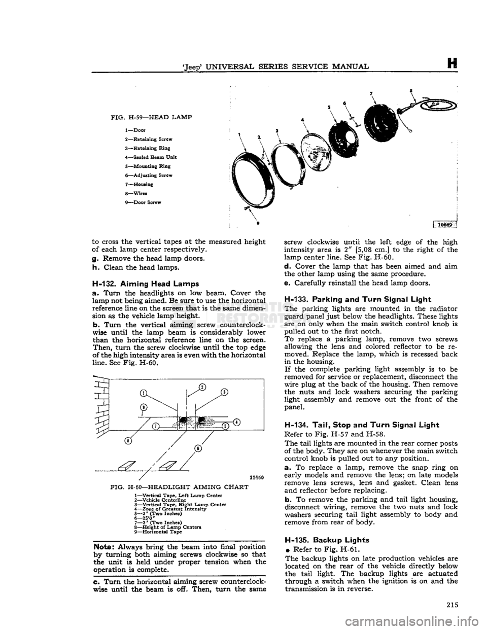
FIG.
H-59—HEAD LAMP
1—
Door
2—
Retaining
Screw
3—
Retaining
Ring
4—
Sealed
Beam
Unit
5—
Mounting
Ring
6—
Adjusting
Screw 7—
Housing
8—
Wires
9—
Door
Screw 310669
to cross the vertical
tapes
at the measured height
of each lamp center respectively.
g.
Remove the head lamp doors.
h.
Clean
the head lamps.
H-132.
Aiming Head Lamps
a.
Turn
the headlights on low beam. Cover the lamp not being aimed. Be sure to use the horizontal reference line on the screen that is the same dimen
sion as the vehicle lamp height.
b.
Turn
the vertical aiming screw counterclock
wise until the lamp beam is considerably lower
than
the horizontal reference line on the screen.
Then,
turn
the screw clockwise until the top
edge
of the high intensity
area
is even with the horizontal
line.
See Fig. H-60.
I
(T)
JT)
1'.'' | '':'
11460
FIG.
H-60—HEADLIGHT AIMING
CHART
1—
Vertical
Tape,
Left
Lamp
Center
2—
Vehicle
Centerline
3—
—Vertical
Tape,
Right
Lamp
Center
4—
Zone
of Greatest Intensity
5—
2
*
(Two Inches)
6— 25'0
'
7—
2
*
(Two Inches)
8—
Height
of
Lamp
Centers
9—
Horizontal
Tape
Note:
Always bring the beam into final position
by turning both aiming screws clockwise so that
the unit is held under proper tension when the operation is complete.
c. Turn
the horizontal aiming screw counterclock
wise until the beam is off.
Then,
turn
the same
screw
clockwise until the
left
edge
of the high
intensity area is 2" [5,08 cm.] to the right of the
lamp center line. See Fig. H-60.
d.
Cover the lamp that has been aimed and aim
the other lamp using the same procedure.
e.
Carefully
reinstall the head lamp doors.
H-133.
Parking
and
Turn Signal Light
The
parking lights are mounted in the radiator
guard
panel just below the headlights. These lights
are
on only when the main switch control knob is
pulled
out to the first notch.
To
replace a parking lamp, remove two screws allowing the lens and colored reflector to be re
moved. Replace the lamp, which is recessed back
in
the housing.
If
the
complete
parking light assembly is to be
removed for service or replacement, disconnect the
wire
plug at the back of the housing.
Then
remove
the nuts and lock washers securing the parking light assembly and remove out the front of the
panel.
H-134. Tail, Stop
and
Turn Signal Light
Refer
to Fig. H-57 and H-58.
The
tail
lights are mounted in the
rear
corner
posts
of the body. They are on whenever the main switch
control
knob is pulled out to any position.
a.
To replace a lamp, remove the snap ring on
early
models
and remove the lens; on late
models
remove lens screws, lens and gasket.
Clean
lens
and
reflector before replacing.
b. To remove the parking and
tail
light housing,
disconnect wiring, remove the two nuts and lock
washers securing
tail
light assembly to body and remove from
rear
of body.
H-135-
Backup Lights •
Refer to Fig. H-61.
The
backup lights on late production vehicles are located on the
rear
of the vehicle directly below
the
tail
light. The backup lights are actuated
through a switch when the ignition is on and the
transmission
is in reverse. 215
Page 320 of 376
STEERING
SYSTEM
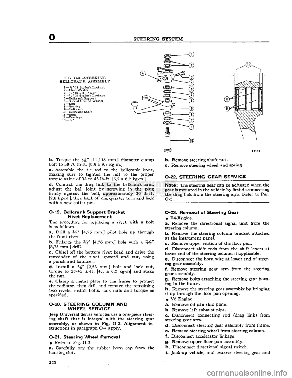
FIG.
0-9—STEERING
BELLCRANK
ASSEMBLY
1— 5s'-18
Stollock
Lockout
2—
Plain
Washer
3— 7 us"-20
x
2 l2' Bolt
4—
71«
*-20
Stollock
Locknut
5—
Beilcrank
Support
6—
Special
Ground
Washer
7— Seal
8—
Bearing
9— Beilcrank
10— Beilcrank
Shaft
11—
Seals
12—
Bearings
13— } s *
b.
Torque the
Vfc"
[11,113
mm.] diameter elamp
bolt to
50-70
lb-ft. [6,9 a 9,7 kg-m.].
c.
Assemble the tie rod to the beilcrank lever,
making
sure to tighten the nut to the proper
torque value of 38 to 45 lb-ft. [5,2 a 6,2 kg-m.].
d.
Connect the drag
link
to the beilcrank arm,
adjust
the
ball
joint by screwing in the plug firmly against the
ball,
approximately 20 lb-ft. [2,8 kg-m.], then back off one quarter
turn
and lock
with
a new cotter pin.
0-19.
Beilcrank
Support
Bracket
Rivet
Replacement
The
procedure for replacing a rivet with a bolt
is as follows:
a.
Drill
a [4,76 mm.] pilot
hole
up through
the front rivet.
b.
Enlarge
the [4,76 mm.]
hole
with a %"
[8,73 mm.]
drill.
c.
Chisel
off the
bottom
rivet head and drive the
remainder
of the rivet upward and out, using
a
punch and hammer.
d.
Install
a %" [9,53 mm.] bolt and lock nut,
torque to
30-45
lb-ft. [4,1 a 6,2 kg-m] and stake
the nut.
e.
Clamp
a metal plate to the frame to protect
the radiator, then
drill
and remove the remaining two rivets, install bolts, lock nuts and torque as
specified.
O-20.
STEERING
COLUMN
AND
WHEEL SERVICE
Jeep
Universal
Series vehicles use a
one-piece
steer
ing
shaft that is integral with the steering gear
assembly, as shown in Fig. 0-2. Alignment in
structions in paragraph 0-4 apply.
0-21.
Steering
Wheel Removal •
Refer to Fig. 0-2.
a.
Carefully
pry the rubber horn cap from the housing slot.
b.
Remove steering shaft nut.
c.
Remove steering wheel and spring.
0-22.
STEERING GEAR SERVICE
Note:
The steering gear can be adjusted when the
gear is mounted in the vehicle by first disconnecting
the drag
link
from the steering arm. Refer to Par.
Q-5.
0-23.
Removal
of
Steering Gear
•
F4-Engine.
a.
Remove the directional signal unit from the steering column.
b.
Remove the steering column bracket attached
at the instrument panel.
c.
Remove upper section of the floor pan.
d.
Disconnect shift rods from the shift levers at
lower end of the steering column if applicable.
e.
Disconnect the horn wire at lower end of steer
ing
gear assembly.
f.
Remove steering gear arm from the steering gear assembly.
g.
Remove
bolts
attaching the steering gear hous
ing
to the frame.
h.
Remove the steering gear assembly by bringing
it
up through the floor pan opening.
•
V6 Engine.
a.
Remove oil pan
skid
plate.
b.
Remove
left
exhaust pipe.
c.
Disconnect connecting rod (drag
link)
from
steering gear arm.
d.
Disconnect steering gear assembly from frame.
e.
Remove steering wheel from steering column.
f. Disconnect accelerator linkage.
g.
Remove upper floor pan assembly.
h.
Disconnect directional signal switch.
i.
Jack-up
vehicle, and remove steering gear and
320
Page 352 of 376
BODY
10728
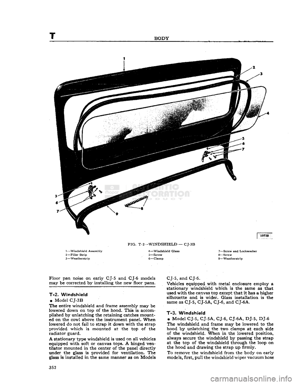
FIG.
T-2—WINDSHIELD
—
CJ-3B
1—
Windshield
Assembly
2—
Filler
Strip
3—
Weatherstrip 4—
Windshield
Glas3
5—
Screw
6—
Clamp
7—
Screw
and Lockwasher
8—
Screw
r
9— —Weatherstrip
Floor
pan
noise
on early CJ-5 and CJ-6
models
may be corrected by installing the new floor pans.
T-2.
Windshield
•
Model
CJ-3B
The
entire windshield and frame assembly may be
lowered down on top of the hood.
This
is accom plished by unlatching the retaining catches mount
ed on the cowl
above
the instrument panel. When lowered do not
fail
to strap it down with the strap provided which is mounted at the top of the
radiator
guard.
A
stationary
type
windshield is used on all vehicles
equipped with
soft
or canvas
tops.
A hinged ven tilator mounted in the center of the panel directly
under the
glass
is provided for ventilation. The
glass
is installed in the same manner as on Models
CJ-5,
and
CJ-6.
Vehicles equipped with metal enclosure employ a
stationary windshield which is the same as that used with the canvas top
except
that it has a higher
silhouette
and is wider.
Glass
installation is the same as
CJ-5,
CJ-5
A, CJ-6,
and
CJ-6
A.
T-3.
Windshield
»
Model
CJ-5, CJ-5A, CJ-6, CJ-6A,
DJ-5, DJ-6
The
windshield and frame may be lowered to the
hood
by unlatching the two clamps at each side
of the windshield. When in the lowered position, always secure the windshield by passing the strap
at the top of the windshield through the
loop
on the
hood
and drawing the strap up firmly.
To
remove the windshield from the
body
on early
models, first,
pull
the windshield wiper vacuum
hose
352
Page 361 of 376
'Jeep*
UNIVERSAL
SERIES
SERVICE
MANUAL
U
DESCRIPTION
—
Continued
AXLES
W-99* Gauge — Pinion & Ring
Gear
Setting
W-104-B* Puller — Tapered Roller Bearing Removing
W-126* Driver — Pinion Bearing Cup
W-128* Installer — Differential Inner Oil Seal W-129 Spreader — Differential
Carrier
Housing
W-138* Driver & Adapter —
King
Pin Bearing
W-144* Wrench — Wheel Bearing Adjusting Nut W-147* Driver — Pinion Oil Seal W-163* Puller
—-
Axle Shaft Drive Flange
W-186* Driver — Axle Shaft Oil Seal
W-188* Driver — Differential Case Bearing W-251* Puller — Pinion Oil Seal
W-262*
Sleeve
— Pinion Bearing Installing
W-263
Semi-Floating
Rear
Axle Shaft Oil Seal W-264* Driver — Pinion Outer Bearing Cup
W-297* Torque Wrench — Pinion Bearing Adjusting W-343* Remover
85
Installer —
Rear
Axle Bearing (Flanged Axle)
W-344* Installer — Pinion Inner Bearing Cups
C-319-A
Puller —
Rear
Wheel Hub (Tapered Axle Shaft)
C-690 Checking Scale —
King
Pin Bearing Preload DD-914-P Press — Tapered Roller Bearing Removing
DD-914-9 Reducer Ring — Differential & Pinion Bearings (Use with DD-914-P)
C-3
716 Driver — Differential
Carrier
Bearing C-4142
Gear
Rotating Tool —
Trac-Lok
Differential
**Jeep*
exclusive
tool
Steering
Group
C-3646 Puller, Steering Shaft Arm
Brake
Group
W-172 Puller, Parking Brake Drum
U-12.
STflNDfiRD
AND
RECOMMENDED
TOOLS
Tool
Description
ENGINE
W-292
Tester — Cooling
System
Thermostat
C-119 Indicator — Cylinder Bore C-385 Compressor — Piston Ring
C-647 Fixture — Spring Testing
C-823
Hone
— Cylinder Bore Refinishing
C-3012 Reamer — Cylinder Ridge
C-3250 Pliers — Radiator fis Heater
Hose
Wire Clamp
C-3411
Gauge — Pressure & Vacuum
C-3422-A Compressor — E-type Valve Spring
C-3501
Hone
— Cylinder
Deglazing
C-3514
Flusher — Cooling
System
C-3886 Fixture — Carburetor Holding C-3896-A Tachometer — Portable
C-3943 Gauge — Compression Checking
C-3952 Torque Wrench, 150
lb-ft.
Swivel Head C-3953 Stand, Engine Repair
C-3959 Light — Ignition Timing
C-4065 Wrench — Oil Filter Removing
C-4080 Tester — Cooling
System
fig
Pressure Cap
ELECTRICAL
40B Hydrometer — Battery Service
W-291 Tester — Instrument
C-3674
Aimers —
Headlight
(Pair)
C-3829 Tester —
Diode
Polarity
C-3888 Tester — Volt-Ampere C-3950 Tester — 12V 60 Amp. Carbon Pile Resistor 361
Page 372 of 376
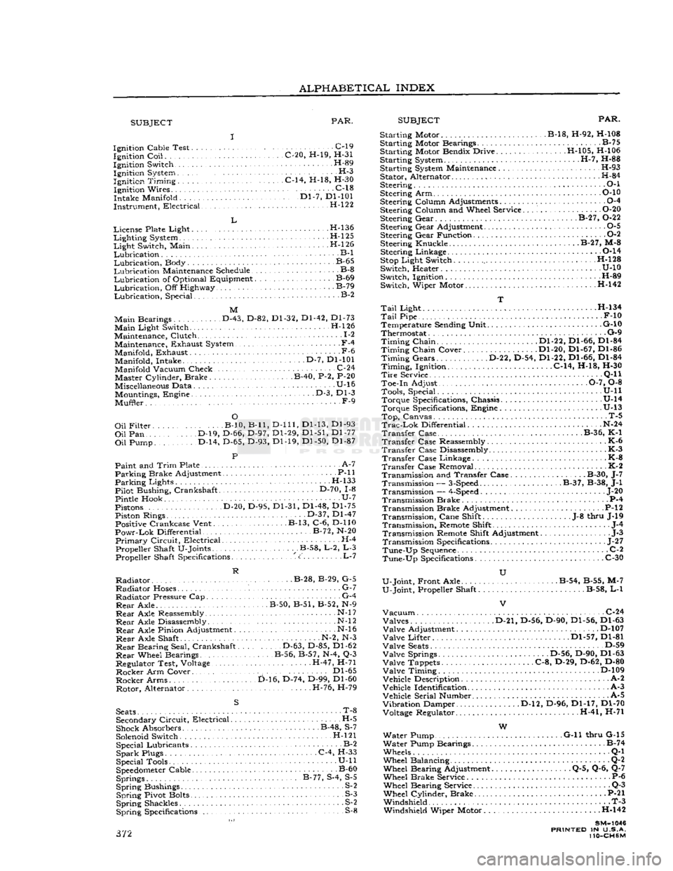
ALPHABETICAL
INDEX
SUBJECT
PAR.
SUBJECT
PAR.
Ignition Cable Test C-l9 Ignition
Coil
C-20, H-19, H-31
Ignition Switch H-89 Ignition System H-3
Ignition
Timing
C-14, H-18, H-30 Ignition Wires C-18
Intake Manifold '." Dl-7, Dl-101
Instrument, Electrical H-122
L
License Plate Light H-l36
Lighting
System H-l25
Light
Switch, Main . H-l 26
Lubrication
B-l
Lubrication,
Body B-65
Lubrication
Maintenance Schedule B-8
Lubrication
of Optional Equipment B-69
Lubrication,
Off Highway B-79
Lubrication,
Special. B-2
M
Main
Bearings D-43, D-82, Dl-32, Dl-42, Dl-73
Main
Light Switch. H-l26
Maintenance, Clutch 1-2 Maintenance, Exhaust System.,
-
F-4
Manifold, Exhaust -F-6 Manifold, Intake D-7, Dl-101
Manifold Vacuum Check. .C-24 Master Cylinder, Brake B-40, P-2, P-20
Miscellaneous Data U-16 Mountings, Engine • • •
-
D-3, Dl-3
Muffler. F-9
O
Oil
Filter B-10, B-ll,
D-lll,
Dl-13, Dl-93
Oil
Pan D-19, D-66, D-97, Dl-29, Dl-51, Dl-77
Oil
Pump. D-14, D-65, D-93, Dl-19, Dl-50, Dl-87
P
Paint and
Trim
Plate • • A-7
Parking
Brake Adjustment P-ll
Parking
Lights H-133
Pilot Bushing, Crankshaft D-70, 1-8
Pintle Hook U-7
Pistons D-20, D-95, Dl-31, Dl-48, Dl-75 Piston Rings. • • •
•
D-37, Dl-47 Positive Crankcase Vent. B-13, C-6, D-110
Powr-Lok
Differential B-72, N-20
Primary
Circuit,
Electrical H-4 Propeller Shaft U-Joints .B-58, L-2, L-3 Propeller Shaft Specifications <:' L-7
R
Radiator
B-28, B-29, G-5
Radiator
Hoses. G-7
Radiator
Pressure Cap G-4
Rear
Axle. B-50, B-51, B-52, N-9
Rear
Axle Reassembly • N-l
7
Rear
Axle Disassembly N-l
2
Rear
Axle Pinion Adjustment N-l6
Rear
Axle Shaft N-2, N-3
Rear
Bearing Seal, Crankshaft D-63, D-85, Dl-62
Rear
Wheel Bearings B-56, B-57, N-4, Q-3
Regulator Test, Voltage H-47, H-71
Rocker
Arm Cover.. . Dl-65
Rocker
Arms D-16, D-74, D-99, Dl-60 Rotor, Alternator H-76, H-79
S
Seats
• T-8 Secondary
Circuit,
Electrical H-5
Shock Absorbers B-48, S-7
Solenoid Switch. H-l21 Special Lubricants B-2
Spark
Plugs C-4, H-33
Special Tools • U-ll
Speedometer
Cable B-60 Springs B-77, S-4, S-5
Spring
Bushings S-2
Spring
Pivot Bolts S-3
Spring
Shackles S^2
Spring
Specifications S-8 372 Starting Motor B-18, H-92, H-108
Starting Motor Bearings B-75
Starting Motor Bendix Drive H-105, H-106
Starting System H-7, H-88
Starting System Maintenance H-93 Stator, Alternator H-84
Steering • • •
•
O-l
Steering Arm P-10
Steering Column Adjustments 0-4
Steering Column and Wheel Service O-20 Steering Gear. . B-27, 0-22
Steering Gear Adjustment 0-5
Steering Gear Function 0-2
Steering Knuckle. B-27, M-8 Steering Linkage 0-14
Stop
Light Switch H-128
Switch, Heater U-10 Switch, Ignition H-89
Switch, Wiper Motor H-142
T
Tail
Light . H-134
Tail
Pipe F-10 Temperature Sending Unit G-10
Thermostat G-9
Timing
Chain Dl-22, Dl-66, Dl-84
Timing
Chain Cover Dl-20, Dl-67, Dl-86
Timing
Gears D-22, D-54, Dl-22, Dl-66, Dl-84
Timing,
Ignition. C-14, H-18, H-30
Tire
Service . •
•
Q-l
1
Toe-in Adjust 0-7, 0-8 Tools, Special. . .
........
U-ll Torque Specifications, Chassis U-14
Torque Specifications, Engine .U-13
Top,
Canvas. T-5
Trac-Lok
Differential N-24
Transfer
Case B-36, K-1
Transfer
Case Reassembly K-6
Transfer
Case Disassembly K-3
Transfer
Case Linkage - K-8
Transfer
Case Removal K-2 Transmission and Transfer Case. B-30, J-7 Transmission —
3-Speed
B-37, B-38, J-l
Transmission —
4-Speed
... J-20
Transmission Brake P-4 Transmission Brake Adjustment P-l
2
Transmission,
Cane Shift .J-8 thru J-19
Transmission,
Remote Shift J-4
Transmission Remote Shift Adjustment J-3
Transmission Specifications
-
J-27
Tune-Up
Sequence
C-2
Tune-Up
Specifications C-30
U
U-Joint, Front Axle . . B-54, B-55, M-7
U-Joint, Propeller Shaft B-58, L-l
Vacuum
C-24 Valves D-21, D-56, D-90, Dl-56, Dl-63
Valve
Adjustment D-107
Valve
Lifter Dl-57, Dl-81
Valve
Seats
D-59
Valve
Springs .D-56, D-90, Dl-63
Valve
Tappets C-8, D-29, D-62, D-80
Valve
Timing D-109
Vehicle Description A-2
Vehicle Identification A-3
Vehicle Serial Number. A-5
Vibration
Damper D-l2, D-96, Dl-17, Dl-70 Voltage Regulator. H-41, H-71
W
Water Pump G-ll thru G-15
Water Pump Bearings B-74
Wheels Q-l
Wheel Balancing Q-2 Wheel Bearing Adjustment Q-5, Q-6, Q-7
Wheel Brake Service P-6 Wheel Bearing Service Q-3
Wheel Cylinder, Brake P-21 Windshield T-3 Windshield Wiper Motor . .H-142
SM-1046
PRINTED
IN U.S.A.
110-CH6M