seats JEEP CJ 1953 Owner's Manual
[x] Cancel search | Manufacturer: JEEP, Model Year: 1953, Model line: CJ, Model: JEEP CJ 1953Pages: 376, PDF Size: 19.96 MB
Page 332 of 376

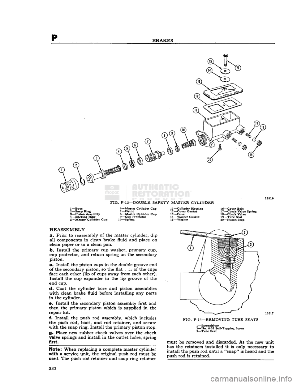
BRAKES
12519
FIG.
P-13—DOUBLE
SAFETY MASTER CYLINDER
1— Boot
2— Snap Ming 3"*—Piston Assembly
4—
Backing
Ring 5—
Master
Cylinder Cup 6—
Master
Cylinder Cup
7— Piston
8—
Master
Cylinder Cup 9—
Cup
Protector
10—Spring 11—
Cylinder
Housing
12—
Cover
Gasket
13—
Cover
14—
Washer
Gasket 15—
Washer
16—
Cover
Bolt
17—
Check
Valve Spring 18—
Check
Valve
19—
Tube
Seat
20— Piston Stop
REASSEMBLY
a.
Prior
to reassembly of the master cylinder, dip
all
components
in clean brake fluid and place on
clean paper or in a clean pan.
b.
Install the primary cup washer, primary cup,
cup protector, and return spring on the secondary piston.
c. Install the piston cups in the double
groove
end
of the secondary piston, so the flat j of the cups face each other (lip of cups away from each other).
Install
the cup expander in the lip
groove
of the
end cup.
cL
Coat the cylinder bore and piston assemblies with clean brake fluid
before
installing any parts
in
the cylinder.
e. Install the secondary piston assembly first and then the primary piston which is supplied in the
repair
kit.
f.
Install the push rod assembly, which includes
the push rod,
boot,
and rod retainer, and secure
with the snap ring. Install the primary piston
stop.
g. Place new rubber check valves over the check valve springs and install in the
outlet
holes, spring
first.
Note:
When replacing a
complete
master cylinder
with a service unit, the original push rod must be used. The push rod retainer and snap ring retainer 12617
FIG.
P-14—REMOVING TUBE SEATS 1
—Screwdriver
2— No. 6-32 Self-Tapping Screw
3—
Tube
Seat must be removed and discarded. As the new unit
has the retainers installed it is only necessary to
install
the push rod until a "snap" is heard and the push rod is retained. 332
Page 333 of 376

'Jeep'
UNIVERSAL
SERIES SERVICE
MANUAL
P h.
Install
the tube seats, flat side toward the check
valve,
and press in with tube nuts or the master
cylinder
brake pipe tube nuts.
BLEEDING
a.
Before the master cylinder is installed on the
car,
the unit must be bled.
b.
Support the cylinder assembly in a vise and
fill
both fluid reservoirs with approved brake fluid,
e.
Loosely install a plug in each
outlet
of the
cylinder.
Depress the push rod several times until
air
bubbles cease to appear in the brake fluid.
d.
Tighten the plugs and attempt to depress the piston. The piston travel should be restricted after
all
air is expelled.
e.
Install
the master cylinder on the car and bleed
the hydraulic lines at the wheel cylinder. Refer to
Par.
P-7.
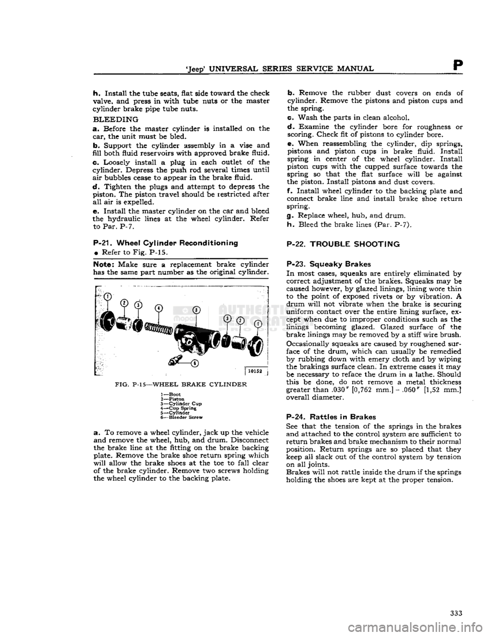
P-21.
Wheel
Cylinder
Reconditioning
•
Refer to Fig. P-15.
Note:
Make sure a replacement brake cylinder
has the same part number as the original cylinder.
FIG.
P-15—WHEEL
BRAKE CYLINDER
1— Boot
2—
Piston
3—
Cylinder
Cup
4—
Cup
Spring
5—
Cylinder
6—
Bleeder
Screw
a.
To remove a wheel cylinder,
jack
up the vehicle
and
remove the wheel, hub, and
drum.
Disconnect
the brake line at the fitting on the brake backing
plate. Remove the brake
shoe
return spring which
will
allow the brake
shoes
at the toe to
fall
clear of the brake cylinder. Remove two screws holding
the wheel cylinder to the backing plate.
b.
Remove the rubber dust covers on ends of
cylinder.
Remove the pistons and piston cups and
the spring.
c.
Wash the parts in clean alcohol.
d.
Examine the cylinder bore for roughness or
scoring.
Check
fit of pistons to cylinder bore.
e. When reassembling the cylinder, dip springs, pistons and piston cups in brake fluid.
Install
spring
in center of the wheel cylinder.
Install
piston cups with the cupped surface towards the
spring
so that the flat surface
will
be against
the piston.
Install
pistons and dust covers.
f.
Install
wheel cylinder to the backing plate and connect brake line and install brake
shoe
return
spring.
g. Replace wheel, hub, and
drum.
h.
Bleed the brake lines (Par. P-7).
P-22. TROUBLE
SHOOTING
P-23.
Squeaky
Brakes
In
most cases, squeaks are entirely eliminated by
correct
adjustment of the brakes. Squeaks may be
caused however, by glazed linings, lining wore thin
to the point of
exposed
rivets or by vibration. A
drum
will
not vibrate when the brake is securing
uniform
contact over the entire lining surface, ex
cept when due to improper conditions such as the
linings becoming glazed.
Glazed
surface of the
brake
linings may be removed by a stiff
wire
brush.
Occasionally
squeaks are caused by roughened
sur
face of the
drum,
which can usually be remedied
by rubbing down with emery cloth and by wiping
the brakings surface clean. In extreme cases it may
be necessary to reface the drum in a lathe. Should
this be done, do not remove a metal thickness greater than .030" [0,762 mm.] - .060" [1,52 mm.]
overall
diameter.
P-24. Rattles
in
Brakes
See that the tension of the springs in the brakes
and
attached to the control system are sufficient to
return
brakes and brake mechanism to their normal
position.
Return
springs are so placed that they
keep all slack out of the control system by tension on all joints.
Brakes
will
not rattle inside the
drum
if the springs
holding the
shoes
are kept at the proper tension. 333
Page 372 of 376

ALPHABETICAL
INDEX
SUBJECT
PAR.
SUBJECT
PAR.
Ignition Cable Test C-l9 Ignition
Coil
C-20, H-19, H-31
Ignition Switch H-89 Ignition System H-3
Ignition
Timing
C-14, H-18, H-30 Ignition Wires C-18
Intake Manifold '." Dl-7, Dl-101
Instrument, Electrical H-122
L
License Plate Light H-l36
Lighting
System H-l25
Light
Switch, Main . H-l 26
Lubrication
B-l
Lubrication,
Body B-65
Lubrication
Maintenance Schedule B-8
Lubrication
of Optional Equipment B-69
Lubrication,
Off Highway B-79
Lubrication,
Special. B-2
M
Main
Bearings D-43, D-82, Dl-32, Dl-42, Dl-73
Main
Light Switch. H-l26
Maintenance, Clutch 1-2 Maintenance, Exhaust System.,
-
F-4
Manifold, Exhaust -F-6 Manifold, Intake D-7, Dl-101
Manifold Vacuum Check. .C-24 Master Cylinder, Brake B-40, P-2, P-20
Miscellaneous Data U-16 Mountings, Engine • • •
-
D-3, Dl-3
Muffler. F-9
O
Oil
Filter B-10, B-ll,
D-lll,
Dl-13, Dl-93
Oil
Pan D-19, D-66, D-97, Dl-29, Dl-51, Dl-77
Oil
Pump. D-14, D-65, D-93, Dl-19, Dl-50, Dl-87
P
Paint and
Trim
Plate • • A-7
Parking
Brake Adjustment P-ll
Parking
Lights H-133
Pilot Bushing, Crankshaft D-70, 1-8
Pintle Hook U-7
Pistons D-20, D-95, Dl-31, Dl-48, Dl-75 Piston Rings. • • •
•
D-37, Dl-47 Positive Crankcase Vent. B-13, C-6, D-110
Powr-Lok
Differential B-72, N-20
Primary
Circuit,
Electrical H-4 Propeller Shaft U-Joints .B-58, L-2, L-3 Propeller Shaft Specifications <:' L-7
R
Radiator
B-28, B-29, G-5
Radiator
Hoses. G-7
Radiator
Pressure Cap G-4
Rear
Axle. B-50, B-51, B-52, N-9
Rear
Axle Reassembly • N-l
7
Rear
Axle Disassembly N-l
2
Rear
Axle Pinion Adjustment N-l6
Rear
Axle Shaft N-2, N-3
Rear
Bearing Seal, Crankshaft D-63, D-85, Dl-62
Rear
Wheel Bearings B-56, B-57, N-4, Q-3
Regulator Test, Voltage H-47, H-71
Rocker
Arm Cover.. . Dl-65
Rocker
Arms D-16, D-74, D-99, Dl-60 Rotor, Alternator H-76, H-79
S
Seats
• T-8 Secondary
Circuit,
Electrical H-5
Shock Absorbers B-48, S-7
Solenoid Switch. H-l21 Special Lubricants B-2
Spark
Plugs C-4, H-33
Special Tools • U-ll
Speedometer
Cable B-60 Springs B-77, S-4, S-5
Spring
Bushings S-2
Spring
Pivot Bolts S-3
Spring
Shackles S^2
Spring
Specifications S-8 372 Starting Motor B-18, H-92, H-108
Starting Motor Bearings B-75
Starting Motor Bendix Drive H-105, H-106
Starting System H-7, H-88
Starting System Maintenance H-93 Stator, Alternator H-84
Steering • • •
•
O-l
Steering Arm P-10
Steering Column Adjustments 0-4
Steering Column and Wheel Service O-20 Steering Gear. . B-27, 0-22
Steering Gear Adjustment 0-5
Steering Gear Function 0-2
Steering Knuckle. B-27, M-8 Steering Linkage 0-14
Stop
Light Switch H-128
Switch, Heater U-10 Switch, Ignition H-89
Switch, Wiper Motor H-142
T
Tail
Light . H-134
Tail
Pipe F-10 Temperature Sending Unit G-10
Thermostat G-9
Timing
Chain Dl-22, Dl-66, Dl-84
Timing
Chain Cover Dl-20, Dl-67, Dl-86
Timing
Gears D-22, D-54, Dl-22, Dl-66, Dl-84
Timing,
Ignition. C-14, H-18, H-30
Tire
Service . •
•
Q-l
1
Toe-in Adjust 0-7, 0-8 Tools, Special. . .
........
U-ll Torque Specifications, Chassis U-14
Torque Specifications, Engine .U-13
Top,
Canvas. T-5
Trac-Lok
Differential N-24
Transfer
Case B-36, K-1
Transfer
Case Reassembly K-6
Transfer
Case Disassembly K-3
Transfer
Case Linkage - K-8
Transfer
Case Removal K-2 Transmission and Transfer Case. B-30, J-7 Transmission —
3-Speed
B-37, B-38, J-l
Transmission —
4-Speed
... J-20
Transmission Brake P-4 Transmission Brake Adjustment P-l
2
Transmission,
Cane Shift .J-8 thru J-19
Transmission,
Remote Shift J-4
Transmission Remote Shift Adjustment J-3
Transmission Specifications
-
J-27
Tune-Up
Sequence
C-2
Tune-Up
Specifications C-30
U
U-Joint, Front Axle . . B-54, B-55, M-7
U-Joint, Propeller Shaft B-58, L-l
Vacuum
C-24 Valves D-21, D-56, D-90, Dl-56, Dl-63
Valve
Adjustment D-107
Valve
Lifter Dl-57, Dl-81
Valve
Seats
D-59
Valve
Springs .D-56, D-90, Dl-63
Valve
Tappets C-8, D-29, D-62, D-80
Valve
Timing D-109
Vehicle Description A-2
Vehicle Identification A-3
Vehicle Serial Number. A-5
Vibration
Damper D-l2, D-96, Dl-17, Dl-70 Voltage Regulator. H-41, H-71
W
Water Pump G-ll thru G-15
Water Pump Bearings B-74
Wheels Q-l
Wheel Balancing Q-2 Wheel Bearing Adjustment Q-5, Q-6, Q-7
Wheel Brake Service P-6 Wheel Bearing Service Q-3
Wheel Cylinder, Brake P-21 Windshield T-3 Windshield Wiper Motor . .H-142
SM-1046
PRINTED
IN U.S.A.
110-CH6M