ESP JEEP CJ 1953 Owner's Guide
[x] Cancel search | Manufacturer: JEEP, Model Year: 1953, Model line: CJ, Model: JEEP CJ 1953Pages: 376, PDF Size: 19.96 MB
Page 314 of 376

STEERING
SYSTEM
O-L
GENERAL
The
steering system on all Jeep Universal vehicles
consists of the steering gear, steering wheel, steering column and shaft, and steering linkage.
This
section covers wheel alignment, steering linkage,
steering gear, steering column and steering wheel.
0-2. Steering
Gear
Function
The
steering gear is a reducing gear. It exchanges a
relatively
large amount of movement with a small force (applied by the driver at the steering wheel), for a much smaller amount of movement with a
greatly increased force through a cam and lever
action type steering gear. The steering gear ratio is 17.9 to 1 on vehicles equipped with the F4
engine
and
19 to 1 with the V6 engine.
0-3. Steering
Linkage
Refer
to Fig. O-l.
The
steering linkage consists of a steering arm at
tached to the steering gear, a steering connecting
rod,
(drag
link),
connecting the steering arm to the
beilcrank,
and a steering tie rod connecting the
beilcrank
to the axle tie rod. The beilcrank pivots
on a pin mounted just to the left of the frame front crossmember. The steering tie rod is connected to
the beilcrank and
extends
to the right
ball
joint as sembly of tie rod. The tie rod
extends
to the wheels,
being connected to their respective steering knuckle
arms
at the wheels.
With
this linkage arrangement,
as the steering arm
moves
rearward,
the front
wheels
turn
to the left. As the steering arm
moves
forward,
the wheels
turn
to the right.
Ball
joints are used to secure the drag
link,
steering
connecting rod and tie rod ends. The
ball
joints
assist in maintaining
good
steering control and con
stant toe-in of the front wheels under all driving conditions. If the
ball
joints
become
worn enough
to allow free motion in the linkage, they should be,
replaced.
Note:
Ball
joint replacement of the tie rod requires
resetting of the wheel toe-in adjustment.
0-4.
Steering
Column
and Gear
Alignment
When
adjusting a steering gear remove all loads
from
the unit by disconnecting the steering con
necting rod (drag
link)
from the steering arm and
also
loosen
the instrument panel bracket and the
steering gear to frame
bolts
to allow the steering
post
to correctly align itself. When retightening the
steering gear to frame
bolts
use a torque wrench
pull
of 45 to 55 lb-ft. [6,2 a 7,6 kg-m.] on the
Vk*
bolts
and 30 to 40 lb-ft. [4,15 a 5,5 kg-m.] on the
Vs"
bolts. 10811
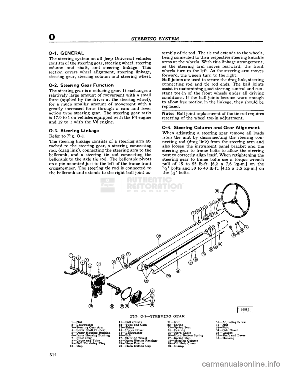
FIG.
0-2—STEERING
GEAR
1—Nut
2
—Lockwasher
3—
Steering
Gear
Arm 4—
Lever
Shaft Oil Seal
5—
Outer
Housing Bushing
6—
Inner
Housing Bushing 7—
Filler
Plug
8—
Cover
and Tube
9—
Ball
Retaining
Ring
10—Cup
11—
Ball
(Steel)
12—
Tube
and Cam
13—
Shims
14—
Upper
Cover
15—
Lockwasher
16—
Bolt
17—
Steering
Wheel 18—
Horn
Button Retainer
19—
Horn
Button
20—
Horn
Button Cap 21— Nut
22—
Spring
23—
Spring
Seat
24—
Bearing
25—
Horn
Cable
26—
Horn
Button Spring
27—
Spring
Cup
28—
Steering Column
29—
Oil
Hole
Cover
30—
Clamp
31—
Adjusting
Screw
32— Nut
33—
Bolt
34—
Side
Cover
35—
Gasket
36—
Shaft
and
Lever
37—
Housing
314
Page 341 of 376

'Jeep'
UNIVERSAL
SERIES
SERVICE
MANUAL
R
FRAME
Contents
SUBJECT
PAR.
Draw
Bar
R-6
Frame
Alignment
.R-2
Frame
Dimensions
.R-3
Front
Axle Alignment.
R-5
Straightening
Frame
R-4
R-1.
GENERAL
equipped with V6 engines, refer
to
measurements
The
frame
is the
structural center
of
the vehicle,
B£?wn
in
FiB-
R"f
, _ , r' .
for in addition
to
carrying
the load,
it
provides and The inost convenient method
of
making this check,
maintains
correct relationship
between
other units
Particularly
when
the
body
is on the
chassis,
is by
to assure their normal functioning. marking
on the
floor
all
dimensional points from
Of
rugged design, the frame
is
constructed of heavy
fhlch
measurements should
be
taken.
This
is
channel
steel side
rails
and cross-members.
Brack-
known
a\
Plumb-bobbing
the
frame Select
a
ets and diagonal braces
are
used
to
maintain
the
?Pace
on the
floof
^hlch
»
extr«nely
level If
work-
proper
longitudinal position
of the
side
rails
rela-
ing Pn
a.,fPen^
c*ean
* s°
that
the fha*k
tive
to
each other, and
at the
same time provide
*****
Jl!*
be
vJs.lble
underneath
the
frame
to be
additional
resistance
to
torsional strains. Fig. R-1, checked
If
workmg
on a
wooden
floor
it is ad-
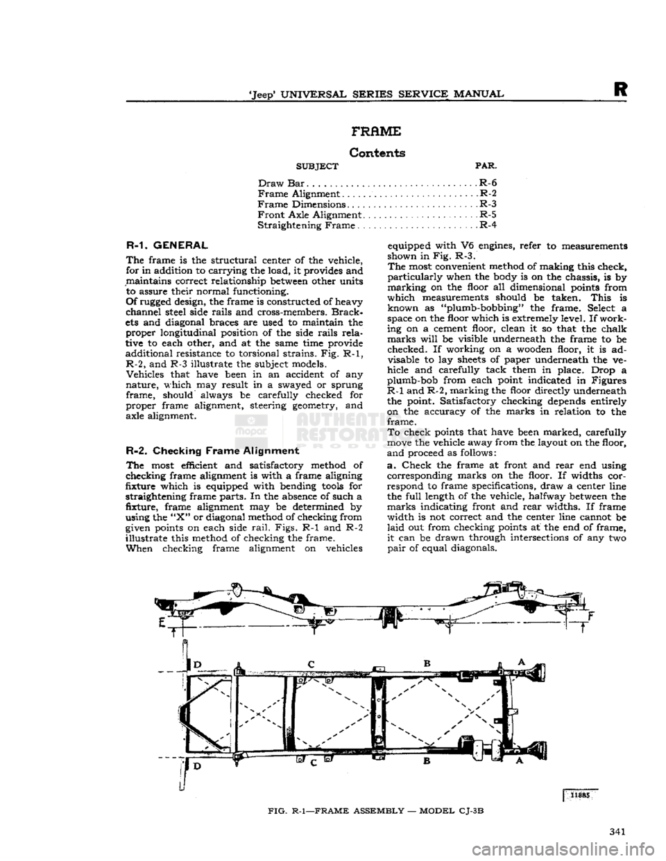
R-2,
and R-3 illustrate
the
subject models. disable
la^
f f * V
Underneath
*he ve"
Vehicles
that have been
in an
accident
of any
hide
and
carefully tack them
m
place. Drop
a
nature,
which
may
result
in a
swayed
or
sprung gumb-bob from each point indicated
in
Figures
frame,
should always
be
carefully checked
for ^
an?
L'maJkl?g the uflo?r
Meetly underneath
proper
frame alignment, steering geometry,
and the
point. Satisfactory checking depends entirely
axle alignment.
on the
accuracy
of the
marks
in
relation
to the
frame.
To
check points that have been marked, carefully
move
the vehicle away from the layout on the floor,
R-2.
Checking
Frame
Alignment
anci
proceed
as
follows:
The
most efficient
and
satisfactory method
of a.
Check
the
frame
at
front
and
rear
end
using
checking
frame alignment
is
with
a
frame aligning corresponding marks
on the
floor.
If
widths
cor-
fixture
which
is
equipped with bending
tools
for
respond
to
frame specifications, draw
a
center line
straightening frame parts. In the absence
of
such
a the
full
length
of
the vehicle, halfway
between
the
fixture,
frame
alignment
may be
determined
by
marks indicating front and
rear
widths.
If
frame
using the
"X"
or diagonal method of checking from width
is not
correct and
the
center line cannot
be
given points
on
each side
rail.
Figs.
R-1 and R-2
laid
out
from checking points
at the
end
of
frame,
illustrate
this method
of
checking
the
frame.
it
can
be
drawn through intersections
of
any
two
When
checking frame alignment
on
vehicles
pair
of
equal diagonals.
FIG.
R-1—FRAME
ASSEMBLY
—
MODEL
CJ-3B
341