ESP JEEP CJ 1953 Owner's Manual
[x] Cancel search | Manufacturer: JEEP, Model Year: 1953, Model line: CJ, Model: JEEP CJ 1953Pages: 376, PDF Size: 19.96 MB
Page 148 of 376
Fl
EXHAUST
EMISSION
CONTROL
SYSTEMS
IMPORTANT
NOTICE
The
Exhaust
Emission Systems covered
in
this publication
meet
State and
Federal
requirements for hydrocarbon and carbon
monoxide
emissions.
To
assure continued proper operation,
these
systems
must
be
inspected
regularly,
parts must be replaced
at
factory-recommended intervals and
engine
tune-up services performed at intervals specified in the
Exhaust
Emission
Con
trol
System Maintenance charts.
For
the
above
reasons,
these
systems
must not, under any circumstances,
be
altered
to anything other than
required
specifications provided in this publication.
Further,
the
Exhaust
Emission
Control
System, or any
of
its components, must
not be physically altered or modified in any respect.
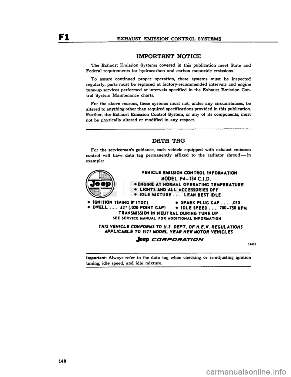
DHTfl
TAG
For
the serviceman's guidance, each vehicle equipped with exhaust emission
control
will
have data
tag
permanently affixed
to the
radiator shroud—-in
example:
VEHICLE
EMISSION
CONTROL
INFORMATION
MODEL
F4-134
C.I.D.
•
ENGINE
AT
NORMAL
OPERATING
TEMPERATURE
•
LIGHTS
AND
ALL
ACCESSORIES OFF
•
IDLE
MIXTURE
. . .
LEAN
BEST
IDLE
•
IGNITION
TIMING
0*
(TDC)
•
SPARK
PLUG
GAP
. . . .030
•
DWELL
...
42* (.020
POINT
GAP)
•
IDLE
SPEED
. . .
700-750 RPM
TRANSMISSION
IN
NEUTRAL
DURING
TUNE
UP
SEE SERVICE MANUAL
FOR
ADDITIONAL INFORMATION
THIS VEHICLE CONFORMS
TO U.S.
DEPT.
OF
H.E.W.
REGULATIONS APPLICABLE
TO
1971 MODEL YEAR NEW MOTOR VEHICLES
Jeep
CORPORATION
14401
Important:
Always refer
to
the data tag when checking or re-adjusting ignition
timing,
idle speed, and idle mixture. 148
Page 149 of 376
'Jeep'
UNIVERSAL SERIES SERVICE
MANUAL
Fl
EXHAUST
EMISSION
CONTROL
SYSTEM
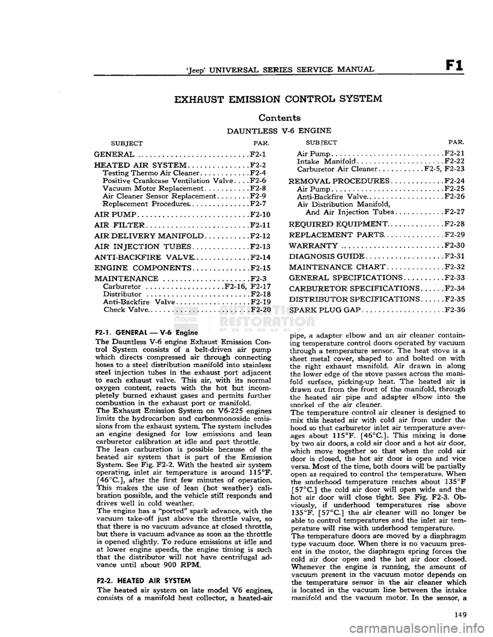
Contents
DAUNTLESS
V-6
ENGINE
SUBJECT
PAR.
GENERAL
.F2-1
HEATED
AIR
SYSTEM.
. F2-2
Testing
Thermo
Air
Cleaner
F2-4
Positive
Crankcase
Ventilation
Valve.
. . .F2-6
Vacuum
Motor Replacement . .F2-8
Air
Cleaner Sensor Replacement F2-9
Replacement Procedures F2-7
AIR
PUMP
.F2-10
AIR
FILTER.
F2-11
AIR
DELIVERY
MANIFOLD.
F2-12
AIR INJECTION TUBES.
F2-13
ANTI-BACKFIRE
VALVE..
.F2-14
ENGINE COMPONENTS
.F2-15
MAINTENANCE
.F2-3
Carburetor
F2-16, F2-17
Distributor
F2-18
Anti-Backfire
Valve . . F2-19
Check
Valve..
F2-20
F2-1.
GENERAL
—V-6
Engine
The
Dauntless V-6
engine
Exhaust
Emission
Con
trol
System consists of a belt-driven air pump
which
directs compressed air through connecting
hoses
to a steel distribution manifold into stainless steel injection
tubes
in the exhaust port adjacent
to each exhaust valve.
This
air, with its normal
oxygen
content, reacts with the hot but incom
pletely burned exhaust
gases
and permits further combustion in the exhaust port or manifold.
The
Exhaust
Emission System on V6-225
engines
limits
the hydrocarbon and carbonmonoxide emissions from the exhaust system. The system includes
an
engine
designed for low emissions and lean
carburetor
calibration at idle and part throttle.
The
lean carburetion is possible because of the
heated air system that is part of the Emission
System.
See Fig. F2-2.
With
the heated air system
operating, inlet air temperature is around
115°F.
[46°C],
after the first few minutes of operation.
This
makes the use of lean (hot weather)
cali
bration
possible, and the vehicle
still
responds and
drives
well in cold weather.
The
engine
has a "ported"
spark
advance, with the
vacuum
take-off just above the throttle valve, so that there is no vacuum advance at closed throttle,
but there is vacuum advance as
soon
as the throttle is opened slightly. To reduce emissions at idle and
at lower
engine
speeds, the
engine
timing is such
that the distributor
will
not have centrifugal ad
vance until about 900 RPM.
F2-2.
HEATED
AIR
SYSTEM
The
heated air system on late model V6 engines,
consists of a manifold heat collector, a heated-air
SUBJECT
PAR.
Air
Pump F2-21
Intake
Manifold F2-22
Carburetor
Air Cleaner F2-5, F2-23
REMOVAL PROCEDURES
F2-24
Air
Pump. F2-25
Anti-Backfire
Valve..
. . .F2-26
Air
Distribution Manifold,
And
Air Injection Tubes F2-27
REQUIRED
EQUIPMENT..
. F2-28
REPLACEMENT
PARTS..
.F2-29
WARRANTY
F2-30
DIAGNOSIS GUIDE
F2-31
MAINTENANCE CHART.
F2-32
GENERAL
SPECIFICATIONS
F2-33
CARBURETOR SPECIFICATIONS.
.... .F2-34
DISTRIBUTOR SPECIFICATIONS
. .F2-35
SPARK PLUG GAP
F2-36
pipe, a adapter elbow and an air cleaner containing temperature control doors operated by vacuum
through a temperature sensor. The heat
stove
is a
sheet
metal cover, shaped to and bolted on with
the right exhaust manifold. Air drawn in along the lower
edge
of the
stove
passes across the mani
fold surface, picking-up heat. The heated air is
drawn
out from the front of the manifold, through
the heated air pipe and adapter elbow into the
snorkel
of the air cleaner.
The
temperature control air cleaner is designed to mix this heated air with cold air from under the
hood so that carburetor inlet air temperature aver
ages
about
115°F.
[46°C.].
This
mixing is
done
by two air doors, a cold air door and a hot air door,
which
move
together
so that when the cold air door is closed, the hot air door is open and vice
versa.
Most of the time, both doors
will
be partially
open as required to control the temperature. When
the underhood temperature reaches about 135
°F
[57°C]
the cold air door
will
open wide and the
hot air door
will
close
tight See Fig. F2-3. Ob viously, if underhood temperatures rise above
135°F.
[57°C]
the air cleaner
will
no longer be
able to control temperatures and the inlet air tem
perature
will
rise with underhood temperature.
The
temperature doors are moved by a diaphragm
type vacuum door. When there is no vacuum pres ent in the motor, the diaphragm spring forces the
cold air door open and the hot air door closed.
Whenever
the
engine
is running, the amount of
vacuum
present in the vacuum motor depends on
the temperature sensor in the air cleaner which is located in the vacuum line
between
the intake
manifold and the vacuum motor. In the sensor, a 149
Page 159 of 376
'Jeep'
UNIVERSAL SERIES SERVICE
MANUAL
F2
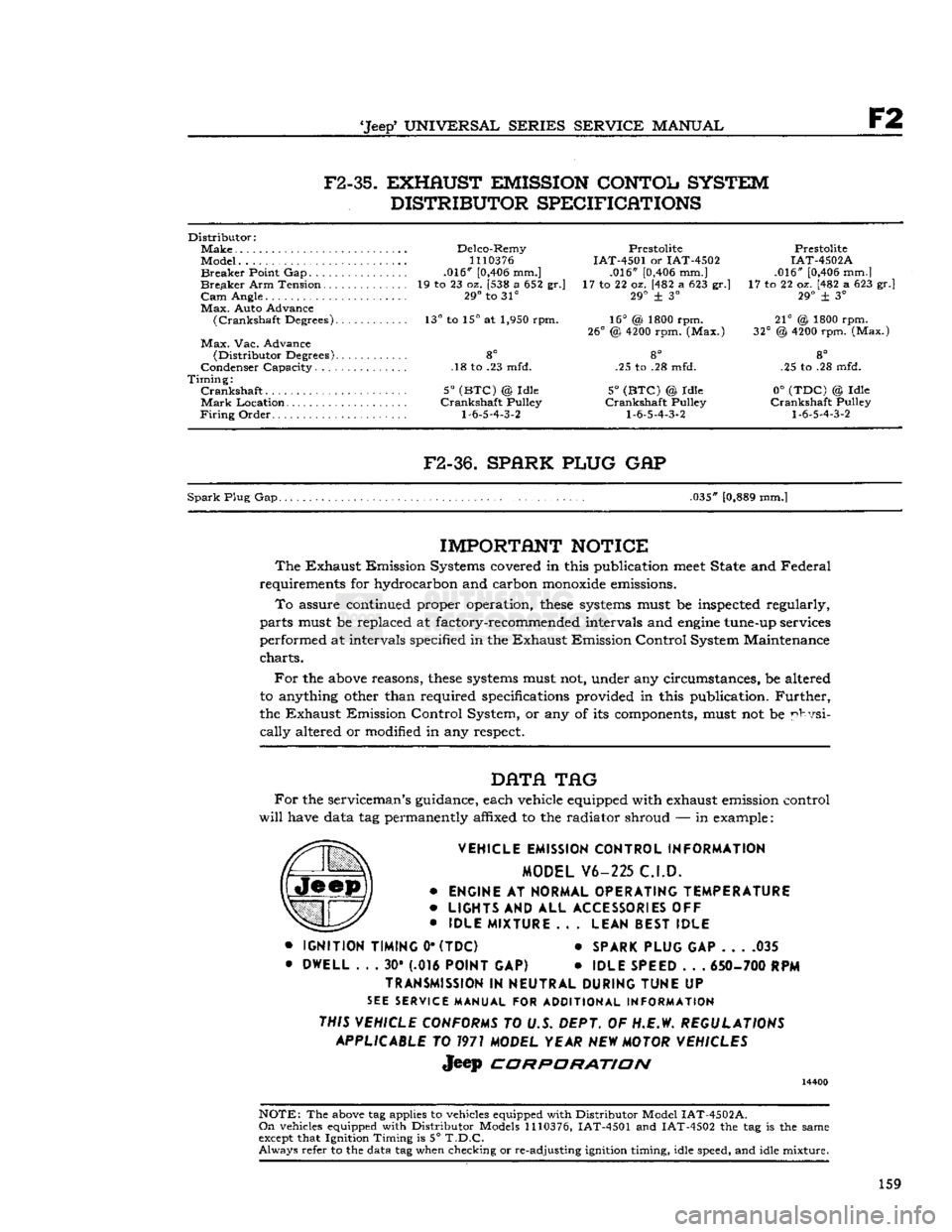
F2-35.
EXHAUST EMISSION CONTOL SYSTEM
DISTRIBUTOR SPECIFICATIONS
Distributor:
Make
Delco-Remy Prestolite Prestolite
Model...
1110376
IAT-4501 or IAT-4502 IAT-4502A
Breaker
Point Gap .016"
[0,406
mm.] .016"
[0,406
mm.] .016"
[0,406
mm.]
Breaker
Arm Tension 19 to 23 oz. [538 a 652 gr.] 17 to 22 oz. [482 a 623 gr.] 17 to 22 oz. [482 a 623 gr.]
Cam
Angle. 29° to 31° 29° + 3° 29° ± 3°
Max.
Auto Advance
(Crankshaft
Degrees). 13° to 15° at 1,950 rpm. 16° (& 1800 rpm. 21° @ 1800 rpm.
26°
@
4200
rpm. (Max.) 32° @
4200
rpm. (Max.)
Max.
Vac. Advance
(Distributor
Degrees) 8° 8° 8°
Condenser Capacity. .18 to .23 mfd. .25 to .28 mfd. .25 to .28 mfd.
Timing:
Crankshaft
5°
(BTC)
@ Idle 5°
(BTC)
© Idle 0°
(TDC)
© Idle
Mark
Location Crankshaft Pulley Crankshaft Pulley Crankshaft Pulley
Firing
Order
1-6-5-4-3-2 1-6-5-4-3-2 1-6-5-4-3-2
F2-36.
SPARK PLUG
GAP
Spark
Plug Gap. .035"
[0,889
mm.]
IMPORTANT
NOTICE
The
Exhaust Emission Systems covered in this publication
meet
State and Federal
requirements for hydrocarbon and carbon
monoxide
emissions.
To
assure continued proper operation,
these
systems
must be inspected regularly,
parts must be replaced at factory-recommended intervals and
engine
tune-up services
performed at intervals specified in the Exhaust Emission Control System Maintenance
charts.
For
the
above
reasons,
these
systems
must not, under any circumstances, be altered
to anything other than required specifications provided in this publication.
Further,
the Exhaust Emission Control System, or any of its components, must not be physi
cally
altered or modified in any respect.
DATA
TAG
For
the serviceman's guidance, each vehicle equipped with exhaust emission control
will
have data tag permanently affixed to the radiator shroud — in example:
VEHICLE EMISSION CONTROL INFORMATION MODEL V6-225 C.I.D.
•
ENGINE
AT
NORMAL OPERATING TEMPERATURE
•
LIGHTS
AND ALL
ACCESSORIES
OFF
•
IDLE MIXTURE
.. .
LEAN BEST IDLE
•
IGNITION TIMING
0*
(TDC)
*
SPARK PLUG
GAP 035
•
DWELL
. . . 30* (.016
POINT
GAP) •
IDLE SPEED
. . .
650- 700
RPM
TRANSMISSION
IN
NEUTRAL DURING TUNE
UP
SEE
SERVICE MANUAL FOR ADDITIONAL INFORMATION
THIS VEHICLE CONFORMS
TO U.S. DEPT. OF H.E.W.
REGULATIONS APPLICABLE
TO
1971
MODEL YEAR
NEW
MOTOR VEHICLES
Jeep
CORPORATION
14400
NOTE:
The
above
tag applies to vehicles equipped with Distributor Model
IAT-4502A.
On
vehicles equipped with Distributor Models
1110376,
IAT-4501 and IAT-4502 the tag is the same
except
that Ignition Timing is 5°
T.D.C.
Always
refer to the data tag when checking or re-adjusting ignition timing, idle speed, and idle mixture.
159
Page 163 of 376

'Jeep*
UNIVERSAL
SERIES SERVICE
MANUAL
G and
scale, especially when used with a flushing
solution. A cleaning solution should be used to
loosen
the rust and scale before reverse flushing
the cooling system.
Flushing
is accomplished through the system in a direction
opposite
to the normal coolant flow.
This
action causes the water to get behind the corrosion
deposits
and force them out. To do this, remove
the upper and lower radiator
hoses.
Then
attach a
drain
hose
at the top of the radiator. Attach a new
piece of
hose
to the radiator
outlet
at the
bottom
and
insert the flushing gun. Connect the water
hose
to the flushing gun to a water
outlet
and the air
hose
to an air line.
Turn
on the water and when
the radiator is
full,
apply the air in short blasts,
allowing the radiator to
fill
between
blasts.
Con
tinue this flushing operation until the water runs
clear
through the top
hose.
With
the thermostat removed, attach a leadaway
hose
to the water
hose
inlet. Also attach a length
of new
hose
to the water
outlet
connection at the
top of the engine.
Turn
the water on and
fill
the
water jacket and then apply air in short blasts.
Continue
this flushing until the water runs clear.
Also
do the hot water heater. Remove heater water
outlet
hose
from heater core. Remove inlet from 163
Page 186 of 376
ELECTRICALJ
SYSTEM
d.
Inspect for
excessive
wear
between
centrifugal
weights
and advance cam and pivot pins.
Turn
weight
base plate in a clockwise direction until
weights
are fully extended. Release and allow
springs to return
weights
to
retard
position. Repeat several times. Springs should return
weights
to
stop
without sticking and there should be no
excessive
free
movement
in the
retard
position. Inspect
springs for distortion and fatigue.
e. Inspect cam
lobes
for scoring or
excessive
wear.
Check
weight
base plate for binding or
excessive
looseness
on distributor shaft.
f.
Check
breaker plate for
excessive
looseness
on
outside
diameter of upper distributor shaft bushing.
Check
breaker plate ground lead for poor
spot
we
Id
at plate end and for
loose
or frayed terminal con
nections.
g.
Check
for
excessive
wear
between
distributor
shaft and bushings in housing. Inspect shaft for distortion. Inspect gear for scoring of
teeth
or
excessive
wear.
h.
Inspect rod end of vacuum advance mechanism
for
excessive
wear. Push rod
into
unit as far as
possible, hold finger tightly over nipple, then re
lease
rod. After about 15 seconds, remove finger
from nipple, and
notice
if air is drawn
into
unit.
If
not, diaphragm is leaking and unit must be
replaced.
H-29.
Distributor Reassembly
Refer
to Fig. H-l5.
a.
Install
distributor
primary
lead and rubber grommet in distributor housing. Mount vacuum
advance unit on housing with two
slotted
attaching
screws; insert ground lead terminal of breaker plate under outer mounting screw.
b.
Install
felt
washer over upper shaft bushing of
distributor housing and apply a few drops of light
oil.
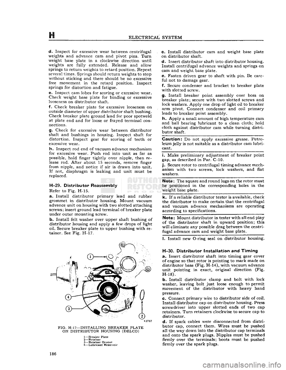
Secure breaker plate to upper bushing with re tainer. See Fig. H-17.
12767
FIG.
H-17—INSTALLING
BREAKER
PLATE
ON
DISTRIBUTOR
HOUSING
(DELCO)
1—
Breaker
Plate
2—
Retainer
3—
Retainer
Groove
4—
Lubricant
Reservoir c.
Install
distributor cam and
weight
base plate
on distributor shaft.
d.
Insert distributor shaft
into
distributor housing.
Install
centrifugal advance
weights
and springs on
cam
and
weight
base plate. e. Fasten driven gear to shaft with pin. Be care
ful
not to damage gear.
f.
Secure condenser and bracket to breaker plate
with
slotted
screw.
g.
Install
breaker point assembly over
boss
on
breaker
plate; secure with two
slotted
screws and
lock washers. Apply one drop of light oil to breaker
arm
pivot. Connect condenser and coil
primary
leads to breaker point assembly.
h.
Apply a small amount of high temperature cam
and
ball
bearing lubricant to a clean cloth; hold cloth against distributor cam while turning
distri
butor shaft.
Caution:
Do not apply
excessive
grease. Petro
leum jelly is not suitable as a distributor cam
lubri
cant.
i.
Make preliminary adjustment of breaker point
gap, as described in Par. C-10.
].
Secure rotor to centrifugal timing advance mech
anism with two screws, lock washers, and flat
washers.
Note:
The square and round
lugs
on the rotor must
be positioned in the corresponding
holes
in the
weight
base plate.
k. If a reliable distributor tester is available, check
the distributor to make certain that the centrifugal
and
vacuum advance mechanisms are operating
according to specifications.
Note:
Mount distributor in tester with all end play
of the distributor shaft in upward position; this
will
eliminate any possible drag
between
the centri fugal advance cam and
weight
base plate.
I.
Install
new
O-ring
seal on distributor housing.
H-30.
Distributor
Installation
and
Timing
a.
Insert distributor shaft
into
timing gear cover
of
engine
so that rotor is pointing to
mark
made on distributor base (Fig. H-14), with vacuum advance
unit pointing in exact, original direction (Fig.
H-18).
b.
Install
distributor clamp and
bolt
with lock
washer, leaving
bolt
just
loose
enough
to permit
movement
of the distributor with heavy hand
pressure.
C.
Connect
primary
wire to distributor side of coil.
Install
distributor cap on distributor housing. Press
screwdriver
into
upper
slotted
ends
of two cap
retainers.
Turn
retainers clockwise to secure cap to distributor.
d.
If
spark
cables were disconnected from
distri
butor cap, connect them. Wires must be pushed
all
the way down
into
the distributor cap terminals
and
onto
the
spark
plugs. Nipples must be pushed
firmly
over the terminals;
boots
must be pushed
firmly
over the
spark
plugs. 186
Page 195 of 376
'Jeep*
UNIVERSAL
SERIES SERVICE
MANUAL
H
no soldering or unsoldering of leads; two complete
rectifying
diode assemblies
which
eliminate the need
for removing and replacing individual diodes; a
corpplete isolation diode assembly; and a rotor
assembly complete with shaft,
pole
pieces, field
coil,
and slip rings.
The
transistorized
voltage
regulator is an electronic
switching device. It
senses
the
voltage
appearing
at the auxiliary terminal of the alternator and
supplies the necessary field current for maintaining
the system
voltage
at the output terminal. The
output current is determined by the battery electri
cal
load; such as headlights, heater, etc.
The
transistorized
voltage
regulator is a sealed
unit,
has no adjustments, and must be replaced
as a complete unit.
H-64. ALTERNATOR
PRECAUTIONS
The
following precautions must be observed to
prevent damage to the alternator and regulator.
a.
Never reverse battery connections. Always
check
the battery polarity with a voltmeter before
any
connections are made to be sure that all con
nections correspond to the battery ground polarity of the vehicle.
b.
Booster batteries for starting must be properly
connected. Make sure that the negative cable of
the booster battery is connected to the negative
terminal
of the battery in the vehicle. The positive
cable of the booster battery should be connected
to the positive terminal of the battery in the
vehicle.
c.
Disconnect the battery cables before using a fast charger.
d.
Never use a fast charger as a booster for
starting
the vehicle.
e.
Never disconnect the
voltage
regulator while
the
engine
is running.
f.
Do not ground the alternator output terminal.
g.
Do not operate the alternator on an open
circuit
with
the field energized.
h.
Do not attempt to polarize an alternator.
These
precautions are stated here as an aid to
service
personnel. They are also restated at appro
priate
places in the
text
of this section of the
manual.
H-65. ALTERNATOR
CHARGING
SYSTEM SERVICE
Important:
All alternator
tests
for the 35, 40 and
55 amp alternator are the same, however, there is a
difference
between
the location of the various ter
minals
and field current specifications. The field
current
of the 35 amp alternator should be 1.7 to 2.3 amps, 40 and 55 amp alternators should be 1.8
to 2.4 amps, with
full
battery
voltage
applied to
the filed coil. Disassembly and assembly procedures
are
the same for all three alternators.
Terminal
locations and wire harness color
codes
for the 35,
40 and 55 amp alternator are shown in Fig. H-38.
H-66.
Service Diagnosis
In
diagnosing a suspected malfunction of the
alternator
charging system, consideration must
be given to the complete electrical power plant of the vehicle; including the alternator, regulator,
ignition switch, charge indicator lamp, battery,
and
all associated wiring. If it is suspected that the
alternator
is not fully charging the battery and
fulfilling
the electrical requirements of the electrical
system, several checks should be made before
checking
the alternator itself:
Note:
Whenever service is required in connection
with
an alternator problem, the first
step
should be to verify that the wiring harness hook-up is correct
as indicated in Fig. H-38.
a.
Test the condition of the battery and
state
of
charge
(Par. H-2).
If the battery is not fully charged
and
in
good
condition, use a replacement battery
for making alternator system
tests.
Caution:
Make certain that the negative battery
post
is connected to ground when making the
battery installation. Serious damage to the alter
nator
can result if battery polarity is reversed.
b.
Check
fan belt for proper tension (Par.
C-27).
Caution:
To increase belt tension, apply pressure
to alternator front housing only as permanent damage can result if pressure is applied to
rear
housing.
H-67.
Alternator In Vehicle Tests
The
following
tests
are made with the alternator
in
the vehicle with output and regulator connec
tions maintained to the alternator except as noted
in
Fig. H-27 and H-28. The field plug and
voltage
regulator are disconnected for
these
tests.
The
tests
are given in proper order and detail in the
following paragraphs.
a.
Isolation Diode Test: To determine if the isola
tion diode is open or shorted, refer to Par. H-69.
b.
Alternator Output Test: To isolate the trouble
to the alternator or regulator, refer to Par. H-70.
c.
Alternator
Field
Circuit
Test: To determine the condition of the field
circuit
(brushes and rotor),
refer
to Par. H-73.
d.
Brush
Insulation
and Continuity
Test:
To deter
mine the condition of the
brush,
refer to
Par.
H-75.
e.
Rotor In-Vehicle Test: To determine whether
the rotor coil is open or shorted, refer to
Par.
H-73.
f. Any further
tests
must be conducted with the
alternator
removed and disassembled. When this
is done, the condition of the rotor, the rectifying
and
isolation diodes, and the stator can be further
tested.
A
commercial alternator tester Sun
Electric
Model
VAT-20
or equivalent can be used to make all
necessary
tests
on the alternator system. If a com
mercial
tester is used, follow the recommended
testing procedure outlined by the tester manu
facturer.
If
a commercial tester is not available, follow the
testing procedure as outlined in this manual.
H-68.
Test Equipment
a.
Volt Ampere Tester such as Sun
Electric
Model
VAT-20
or equivalent with meter ranges as shown
in
the following list can be used. 195
Page 212 of 376
H
ELECTRICAL
SYSTEM
H-124. Testing Indicators and Gauges
Two
gauges
(fuel and temperature) and two in dicators (oil pressure and battery charge) that are
located in the instrument cluster are electrically operated.
The
fuel
gauge
is connected by a single wire to a
float-and-slide-rheostat sending unit in the fuel
tank.
The
temperature
gauge
is connected by a single
wire
to a resistance-type sending unit mounted on the engine.
The
battery charge indicator operates when there
is a difference in potential
between
the generator
and
the battery
.The
battery charge indicator lights
when the generator is not charging the battery. The
indicator
light
goes
out when the generator
begins
to charge the battery.
The
oil pressure indicator is connected by a single
wire
to a diaphragm switch located on the engine.
When
engine
oil pressure is low or zero and the
ignition switch is on, the oil pressure indicator
will
light. When
engine
speed is increased slightly above idle speed, raising the oil pressure to approximately 6 psi. [0,2 kg-cm2], the diaphragm switch
will
open the circuit and the indicator light
will
go out.
A
voltage
regulator maintains a constant
voltage
to the
gauges
in normal operation. On early vehicles,
this
voltage
regulator was mounted on the
rear
of
the instrument cluster. On current vehicles, the
voltage
regulator is integral with the fuel
gauge.
Should
trouble
develop
in the
gauges,
first check the regulator (fuel
gauge
on current production vehicle). If the
voltage
to the regulator is below 10 volts system low
gauge
readings
will
result.
Voltage in
excess
of 16 volts
will
not affect
gauge
readings but may result in premature wear of the
regulator contacts. If the
voltage
to the regulator is
within
the above limits, check the electrical con nections to the regulator (or fuel gauge), especially
the ground connection. If the readings of all the
gauges
is too high, or they all read too low, replace
the regulator (or fuel gauge).
If
the temperature
gauge
or heat indicator in the
instrument cluster have failed, the cause may
originate from the jumper bar shorting out against the instrument case.
Check
the jumper bar
between
the temperature
gauge
and heat indicator at the
rear
of the instrument case. On later production vehicles, the jumper bar is covered with an in
sulating
sleeve
to protect it from shorting out
against the instrument case. If the jumper bar
does
not have this
sleeve,
either install one or
wrap
the bar with plastic electrical tape to
half
an
inch [12,7 mm.] from each end. When installing the jumper bar, be sure the curved
segment
is
closest to the fuel
gauge.
Should
only one of the two
gauges
register incor
rectly,
check the lead wire from the
gauge
to the
sending unit for shorts or open connections. Next disconnect the
gauge
from the sending unit, and
connect the
gauge
to a new fuel tank sending unit
which
has been grounded to the vehicle.
If
the
gauge
registers incorrectly when operating the new unit,
replace the
gauge;
if correctly, replace the sending
unit.
Should
a new fuel tank unit not be available for testing, use a 12-volt
test
light in its place. When
the
gauge
is operating correctly, the pointer
will
move
approximately three-quarters across the
dial.
On
some
vehicles, the temperature
gauge
may
register on or
close
to the H (hot)
mark
when
coolant temperature is
190°F.
to
200°F.
[88°C.
a
93°C.].
In such cases, a 25-ohm,
1-watt
resistor
may be installed on the temperature
gauge
which
will
place the pointer just beyond the center
mark
at a coolant temperature of
190°F.
to
200°F.
Install
the resistor
between
the two terminals on the back
of the
gauge.
Insulate the
exposed
leads of the resistor with electrical tape.
If
the oil pressure indicator
does
not indicate cor
rectly,
first check the light bulb. Next check all
connections and lead wires. If, after all possible
defects
are corrected, the indicator light
does
not go on and off properly, then the diaphragm type
switch in the cylinder block should be replaced.
H-12S.
LIGHTING SYSTEM The
wiring of the lighting systems is shown in
the wiring diagrams, which indicate the various units in relation to their positions in the vehicle.
The
wires in the various circuits are of different
colors or are marked by tracers to aid when check
ing individual circuits.
The
lighting circuits of all models are protected by
an
overload circuit breaker mounted on the back of the main light switch and no replaceable fuse is
required.
The
upper and lower headlight beams are con
trolled by a
foot
switch located on the toe board
to the left of the clutch pedal.
H-126.
Main
Light
Switch
This
switch is a dual functioning unit having two
push-pull
positions and a rotary action. When
pulled out to the first position, the front parking
and
tail
lights are turned on. When pulled all the
way out to the second position, the headlights and
tail
lights are turned on. Rotating the switch to
the right dims the instrument cluster lighting.
The
switch may be removed from the instrument
panel by first loosening the set screw in the control
knob and removing the knob. The retaining nut may then be removed and the switch removed
through the
rear
of the instrument panel.
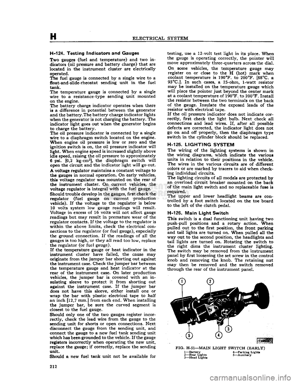
FIG.
H-51—MAIN
LIGHT
SWITCH
(EARLY)
1—
Battery
4—Parking Lights
2—
Rear
Lights 5—Auxiliary
3—
Head
Lights
212
Page 215 of 376
'Jeep*
UNIVERSAL
SERIES
SERVICE
MANUAL
H
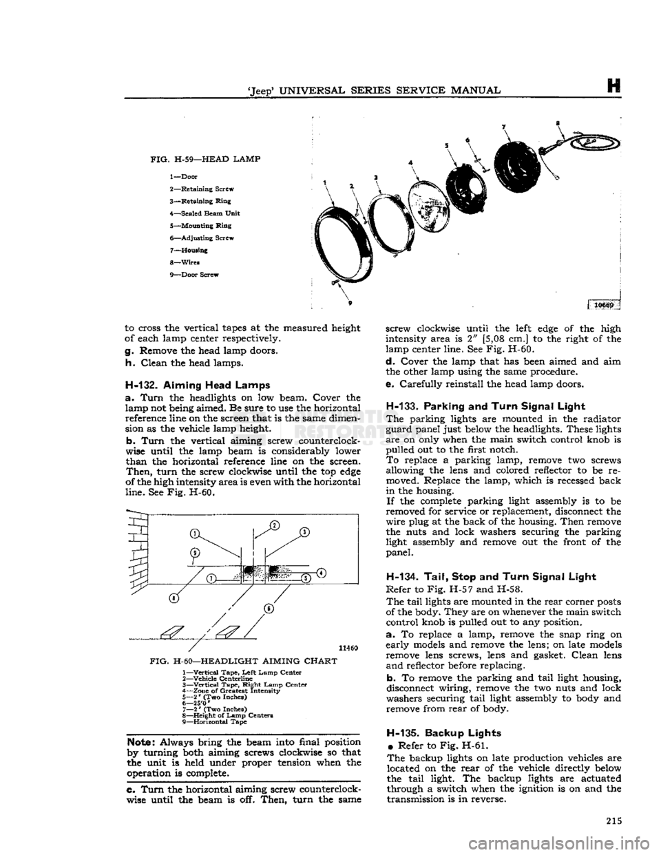
FIG.
H-59—HEAD LAMP
1—
Door
2—
Retaining
Screw
3—
Retaining
Ring
4—
Sealed
Beam
Unit
5—
Mounting
Ring
6—
Adjusting
Screw 7—
Housing
8—
Wires
9—
Door
Screw 310669
to cross the vertical
tapes
at the measured height
of each lamp center respectively.
g.
Remove the head lamp doors.
h.
Clean
the head lamps.
H-132.
Aiming Head Lamps
a.
Turn
the headlights on low beam. Cover the lamp not being aimed. Be sure to use the horizontal reference line on the screen that is the same dimen
sion as the vehicle lamp height.
b.
Turn
the vertical aiming screw counterclock
wise until the lamp beam is considerably lower
than
the horizontal reference line on the screen.
Then,
turn
the screw clockwise until the top
edge
of the high intensity
area
is even with the horizontal
line.
See Fig. H-60.
I
(T)
JT)
1'.'' | '':'
11460
FIG.
H-60—HEADLIGHT AIMING
CHART
1—
Vertical
Tape,
Left
Lamp
Center
2—
Vehicle
Centerline
3—
—Vertical
Tape,
Right
Lamp
Center
4—
Zone
of Greatest Intensity
5—
2
*
(Two Inches)
6— 25'0
'
7—
2
*
(Two Inches)
8—
Height
of
Lamp
Centers
9—
Horizontal
Tape
Note:
Always bring the beam into final position
by turning both aiming screws clockwise so that
the unit is held under proper tension when the operation is complete.
c. Turn
the horizontal aiming screw counterclock
wise until the beam is off.
Then,
turn
the same
screw
clockwise until the
left
edge
of the high
intensity area is 2" [5,08 cm.] to the right of the
lamp center line. See Fig. H-60.
d.
Cover the lamp that has been aimed and aim
the other lamp using the same procedure.
e.
Carefully
reinstall the head lamp doors.
H-133.
Parking
and
Turn Signal Light
The
parking lights are mounted in the radiator
guard
panel just below the headlights. These lights
are
on only when the main switch control knob is
pulled
out to the first notch.
To
replace a parking lamp, remove two screws allowing the lens and colored reflector to be re
moved. Replace the lamp, which is recessed back
in
the housing.
If
the
complete
parking light assembly is to be
removed for service or replacement, disconnect the
wire
plug at the back of the housing.
Then
remove
the nuts and lock washers securing the parking light assembly and remove out the front of the
panel.
H-134. Tail, Stop
and
Turn Signal Light
Refer
to Fig. H-57 and H-58.
The
tail
lights are mounted in the
rear
corner
posts
of the body. They are on whenever the main switch
control
knob is pulled out to any position.
a.
To replace a lamp, remove the snap ring on
early
models
and remove the lens; on late
models
remove lens screws, lens and gasket.
Clean
lens
and
reflector before replacing.
b. To remove the parking and
tail
light housing,
disconnect wiring, remove the two nuts and lock
washers securing
tail
light assembly to body and remove from
rear
of body.
H-135-
Backup Lights •
Refer to Fig. H-61.
The
backup lights on late production vehicles are located on the
rear
of the vehicle directly below
the
tail
light. The backup lights are actuated
through a switch when the ignition is on and the
transmission
is in reverse. 215
Page 232 of 376
CLUTCH
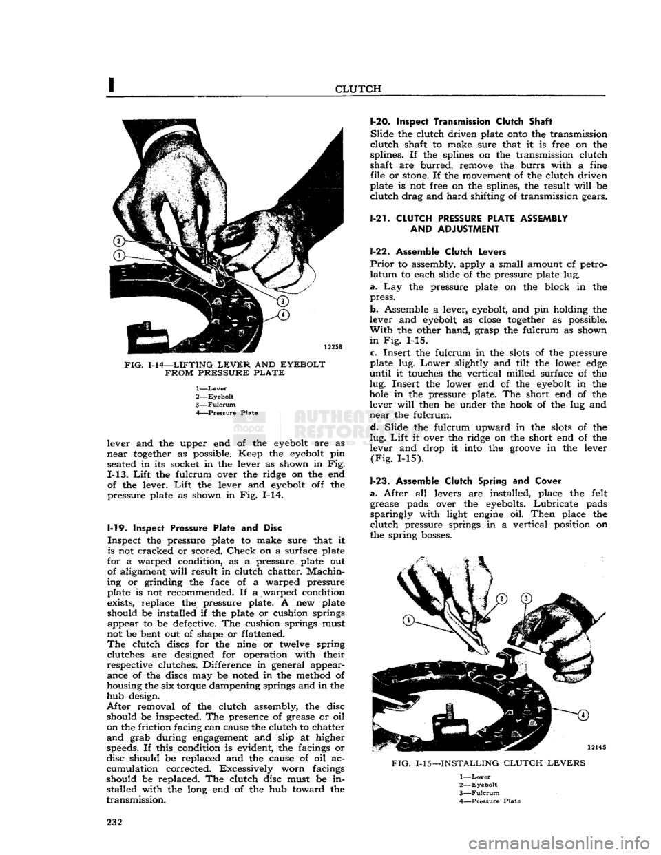
FIG.
1-14—LIFTING
LEVER
AND
EYEBOLT FROM PRESSURE PLATE
1—
Lever
2—
Eyebolt
3—
Fulcrum
A Pressure Plate
lever and the upper end of the
eyebolt
are as
near
together
as possible. Keep the
eyebolt
pin seated in its socket in the lever as shown in Fig.
1-13.
Lift
the fulcrum over the ridge on the end of the lever.
Lift
the lever and
eyebolt
off the
pressure plate as shown in Fig. 1-14.
1-19.
Inspect
Pressure Plate and Disc
Inspect the pressure plate to make sure that it is not cracked or scored.
Check
on a surface plate
for a warped condition, as a pressure plate out of alignment
will
result in clutch chatter.
Machin
ing or grinding the face of a warped pressure
plate is not recommended. If a warped condition
exists, replace the pressure plate. A new plate
should be installed if the plate or cushion springs appear to be defective. The cushion springs must
not be bent out of shape or flattened.
The
clutch discs for the nine or twelve spring clutches are designed for operation with their
respective clutches. Difference in general appear ance of the discs may be noted in the method of
housing the six torque dampening springs and in the
hub design.
After
removal of the clutch assembly, the disc should be inspected. The presence of grease or oil
on the friction facing can cause the clutch to chatter
and
grab during
engagement
and slip at higher speeds. If this condition is evident, the facings or
disc should be replaced and the cause of oil ac
cumulation corrected. Excessively worn facings
should be replaced. The clutch disc must be in stalled with the long end of the hub toward the
transmission.
1-20.
Inspect Transmission Clutch
Shaft
Slide
the clutch driven plate
onto
the transmission
clutch
shaft to make sure that it is free on the
splines. If the splines on the transmission clutch
shaft are
burred,
remove the
burrs
with a fine file or
stone.
If the movement of the clutch driven
plate is not free on the splines, the result
will
be
clutch
drag and
hard
shifting of transmission gears.
1-21.
CLUTCH
PRESSURE
PLATE ASSEMBLY AND
ADJUSTMENT
1-22. Assemble
Clutch
Levers
Prior
to assembly, apply a small amount of petro
latum
to each slide of the pressure plate lug.
a.
Lay the pressure plate on the block in the
press.
b. Assemble a lever,
eyebolt,
and pin holding the
lever and
eyebolt
as
close
together
as possible.
With
the other hand, grasp the fulcrum as shown
in
Fig. 1-15.
c.
Insert the fulcrum in the
slots
of the pressure
plate lug.
Lower
slightly and tilt the lower
edge
until
it touches the vertical milled surface of the
lug.
Insert the lower end of the
eyebolt
in the
hole
in the pressure plate. The short end of the lever
will
then be under the hook of the lug and
near
the fulcrum.
d.
Slide the fulcrum upward in the
slots
of the
lug.
Lift
it over the ridge on the short end of the
lever and drop it into the
groove
in the lever
(Fig.
1-15).
1-23.
Assemble
Clutch
Spring and
Cover
a.
After all levers are installed, place the felt grease pads over the eyebolts.
Lubricate
pads
sparingly
with light
engine
oil.
Then
place the
clutch
pressure springs in a vertical position on
the spring
bosses.
FIG.
1-15—INSTALLING
CLUTCH LEVERS
1—
Lover
2—
Eyebolt
3—
Fulcrum
4—
Pressure
Plate
232
Page 302 of 376
N
REAR
AXLE a.
Place the transmission in neutral.
b.
Raise one wheel off the floor and place a block
in
front and at the
rear
of the
opposite
wheel.
c.
Apply a torque wrench to the axle shaft nut of
the elevated wheel.
d.
Turn
wheel with torque wrench. Disregard
breakaway
torque and observe torque required to
continuously
turn
wheel smoothly. Torque should
read
40 lb-ft [5,53 kg-m.] or more.
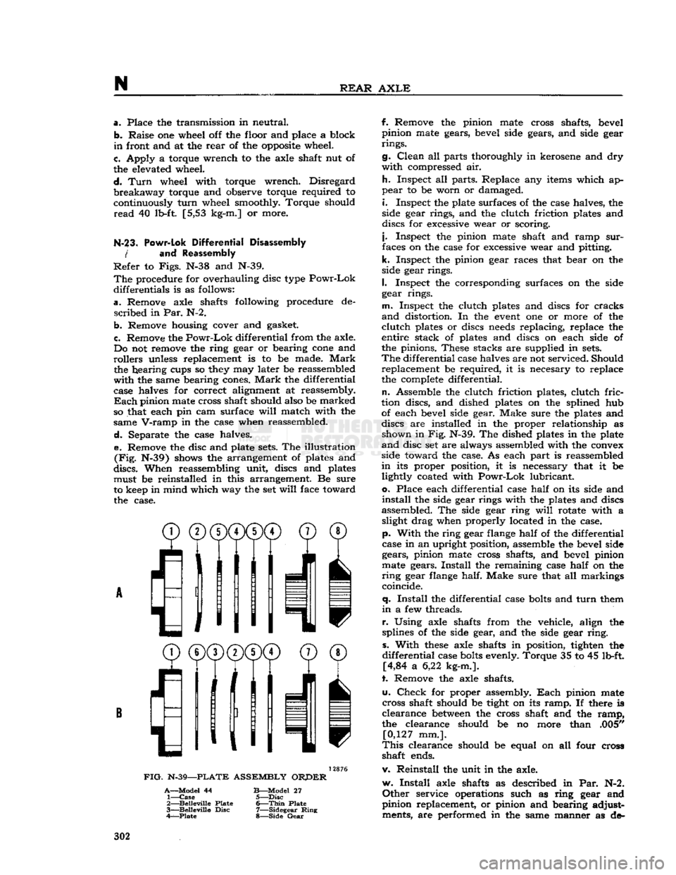
N-23. Powr-Lok
Differential Disassembly
/
and Reassembly
Refer
to
Figs.
N-38 and N-39.
The
procedure for overhauling disc type
Powr-Lok
differentials is as follows:
a.
Remove axle shafts following procedure de
scribed
in Par. N-2.
b.
Remove housing cover and gasket.
c.
Remove the
Powr-Lok
differential from the axle.
Do not remove the ring gear or bearing
cone
and
rollers
unless replacement is to be made.
Mark
the hearing cups so they may later be reassembled
with
the same bearing cones.
Mark
the differential
case halves for correct alignment at reassembly.
Each
pinion mate cross shaft should also be marked
so that each pin cam surface
will
match with the
same
V-ramp
in the case when reassembled.
d.
Separate the case halves. e. Remove the disc and plate
sets.
The illustration
(Fig.
N-39) shows the arrangement of plates and
discs.
When reassembling unit, discs and plates must be reinstalled in this arrangement. Be sure
to keep in mind which way the set
will
face toward the case.
^®(j)(j)CD©
® /'Ml
I
11
11 v
FIG.
N-39—PLATE
ASSEMBLY
ORPER
A—Model
44
B—Model
27 1—
Case
5—Disc
2—
Belleville
Plate
6—Thin
Plate
3—
Belleville
Disc
7—Sidegear
Ring
4—Plate
8—Side
Gear
f. Remove the pinion mate cross shafts, bevel
pinion mate gears, bevel side gears, and side gear
rings.
g.
Clean
all parts thoroughly in kerosene and dry
with
compressed air.
h.
Inspect all parts. Replace any items which ap
pear
to be worn or damaged.
i.
Inspect the plate surfaces of the case halves, the
side gear rings, and the clutch friction plates and
discs for excessive wear or scoring.
j.
Inspect the pinion mate shaft and ramp
sur
faces on the case for excessive wear and pitting,
k.
Inspect the pinion gear races that bear on the
side gear rings.
I.
Inspect the corresponding surfaces on the side
gear rings.
m.
Inspect the clutch plates and discs for cracks
and
distortion. In the
event
one or more of the
clutch
plates or discs
needs
replacing, replace the
entire stack of plates and discs on each side of
the pinions. These stacks are supplied in
sets.
The
differential case halves are not serviced. Should replacement be required, it is necesary to replace
the complete differential.
n.
Assemble the clutch friction plates, clutch
fric
tion discs, and dished plates on the splined hub of each bevel side gear. Make sure the plates and
discs are installed in the proper relationship as shown in Fig. N-39. The dished plates in the plate
and
disc set are always assembled with the convex
side toward the case. As each part is reassembled
in
its proper position, it is necessary that it be lightly coated with
Powr-Lok
lubricant,
o.
Place each differential case
half
on its side and
install
the side gear rings with the plates and discs
assembled. The side gear ring
will
rotate with a slight drag when properly located in the case,
p.
With
the ring gear flange
half
of the differential
case in an upright position, assemble the bevel side gears, pinion mate cross shafts, and bevel pinion
mate gears.
Install
the remaining case
half
on the
ring
gear flange half. Make sure that all markings
coincide.
q.
Install
the differential case
bolts
and
turn
them
in
a few threads.
r.
Using axle shafts from the vehicle, align the
splines of the side gear, and the side gear
ring,
s.
With
these
axle shafts in position, tighten the
differential
case
bolts
evenly. Torque 35 to 45 lb-ft. [4,84 a 6,22 kg-m.].
t. Remove the axle shafts.
u.
Check
for proper assembly.
Each
pinion mate
cross shaft should be tight on its
ramp.
If there is
clearance
between
the cross shaft and the
ramp,
the clearance should be no more than .005" [0,127 mm.].
This
clearance should be equal on all four cross
shaft ends.
v. Reinstall the unit in the axle.
w.
Install
axle shafts as described in Par. N-2.
Other
service operations such as ring gear and
pinion replacement, or pinion and bearing adjust ments, are performed in the same manner as de- 302