steering JEEP CJ 1953 Owner's Guide
[x] Cancel search | Manufacturer: JEEP, Model Year: 1953, Model line: CJ, Model: JEEP CJ 1953Pages: 376, PDF Size: 19.96 MB
Page 336 of 376
Q
WHEELS
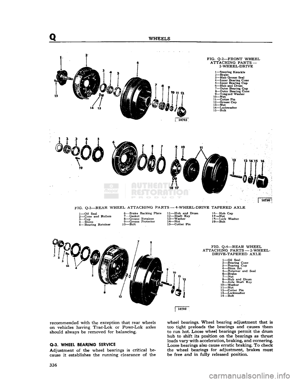
FIG.
Q-2—FRONT
WHEEL
ATTACHING
PARTS —
2-WHEEL-DRIVE
1—
Steering
Knuckle
2—
Brake
3— Hub
Grease
Seal
4—
Inner
Bearing
Cone
5—
Inner
Bearing
Cup
6—
Hub
and
Drum
7—
Outer
Bearing
Cup
8—
Outer
Bearing
Cone
9—
Tongued
Washer
10— Nut
11—
Cotter
Pin
12—
Grease
Cap
13— Nut
14—
Lockwasher
15—
Bolt
j
10703
is ir 10730
FIG.
Q-3—REAR
WHEEL
ATTACHING PARTS —
4-WHEEL-DRIVE
TAPERED
AXLE
1—
Oil
Seal
2—
Cone
and
Rollers
3— Cup
4—
Shims
5—
Bearing
Retainer
6—
Brake
Backing
Plate
7—
Gasket
8—
Grease
Retainer
9—
Grease
Protector
10—Bolt
11— Hub
and
Drum
12—
Shaft
Key
13—
Washer
14—
Nut
15—
Cotter
Pin
Ifi—Hub
Cap
17—Nut
18—
Ixick
Washer
19—Bolt
FIG.
Q-4—REAR
WHEEL
ATTACHING
PARTS —
2-WHEEL-
DRIVE-TAPERED
AXLE
1—
Oil
Seal
2—
Bearing
Cone
3—
Bearing
Cup
4—
Shim
Set
5—
Retainer
and
Seal
6—
Brake
7—
Nut
8—
Hub
and
Drum
9—
Axle
Shaft Key
10—
Washer
11— Nut
12—
Cotter
Pin
13—
Lockwasher
14—
Bolt
recommended with the exception that
rear
wheels
on vehicles having
Trac-Lok
or
Powr-Lok
axles
should always be removed for balancing.
Q-3. WHEEL
BEARING
SERVICE
Adjustment
of the wheel bearings is
critical
be cause it establishes the running clearance of the wheel bearings. Wheel bearing adjustment that is
too
tight
preloads the bearings and causes them
to run hot. Loose wheel bearings permit the drum hub to shift its position on the bearings as thrust loads
vary
with acceleration,
braking,
and cornering.
Loose
bearings also cause
erratic
braking.
To check
the wheel bearings for adjustment, brakes must
be free and in fully released position. 336
Page 337 of 376
'Jeep'
UNIVERSAL
SERIES SERVICE
MANUAL
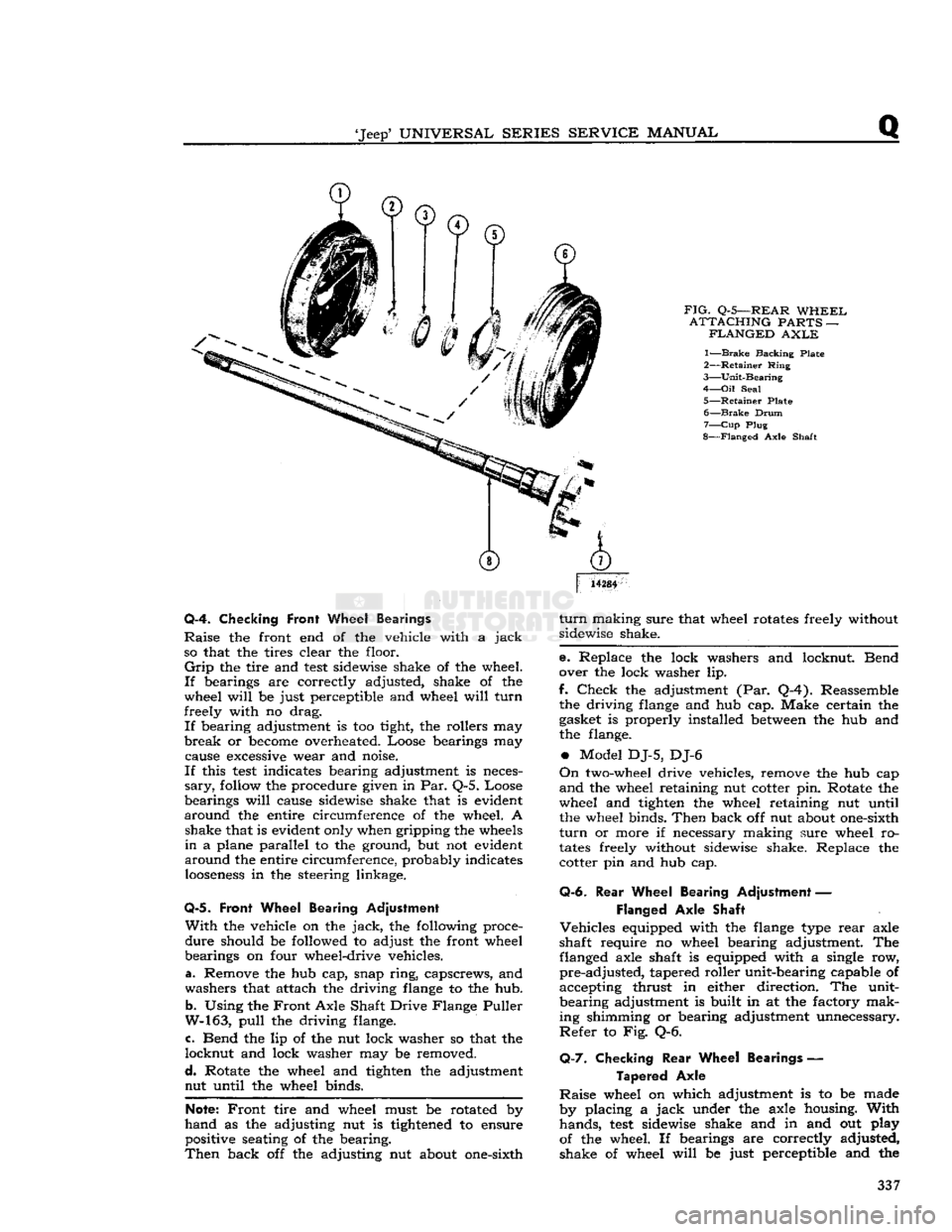
FIG.
Q-5—REAR
WHEEL
ATTACHING
PARTS —
FLANGED
AXLE
1—
Brake
Backing Plate
2—
Retainer
Ring
3—
Unit-Bearing
4—
Oil
Seal
5—
Retainer
Plate 6—
Brake
Drum
7—
Cup
Plug
8—
Flanged
Axle Shaft
14284
Q-4. Checking
Front
Wheel Bearings
Raise
the front end of the vehicle with a
jack
so that the tires clear the floor.
Grip
the tire and
test
sidewise shake of the wheel.
If
bearings are correctly adjusted, shake of the
wheel
will
be just perceptible and wheel
will
turn
freely with no drag.
If
bearing adjustment is too tight, the rollers may
break
or
become
overheated. Loose bearings may cause
excessive
wear and noise.
If
this
test
indicates bearing adjustment is neces
sary,
follow
the procedure given in Par. Q-5. Loose
bearings
will
cause sidewise shake that is evident
around
the entire circumference of the wheel. A shake that is evident only when gripping the
wheels
in
a plane parallel to the ground, but not evident
around
the entire circumference, probably indicates
looseness
in the steering linkage.
Q-5.
Front Wheel Bearing Adjustment
With
the vehicle on the
jack,
the following proce
dure
should be followed to adjust the front wheel
bearings on four wheel-drive vehicles.
a. Remove the hub cap, snap
ring,
capscrews, and
washers that attach the driving
flange
to the hub.
b.
Using the
Front
Axle Shaft Drive Flange Puller
W-163,
pull
the driving flange.
c. Bend the lip of the nut lock washer so that the
locknut
and lock washer may be removed.
d.
Rotate the wheel and tighten the adjustment nut until the wheel binds.
Note:
Front
tire and wheel must be rotated by
hand
as the adjusting nut is
tightened
to ensure positive seating of the bearing.
Then
back off the adjusting nut about one-sixth
turn
making sure that wheel rotates freely without
sidewise shake.
e. Replace the lock washers and locknut. Bend
over the lock washer lip.
f.
Check
the adjustment (Par. Q-4). Reassemble the driving
flange
and hub cap. Make certain the
gasket is properly installed
between
the hub and
the flange.
•
Model DJ-5, DJ-6
On
two-wheel drive vehicles, remove the hub cap
and
the wheel retaining nut cotter pin. Rotate the
wheel and tighten the wheel retaining nut until the wheel binds.
Then
back off nut about one-sixth
turn
or more if necessary making sure wheel ro
tates
freely without sidewise shake. Replace the cotter pin and hub cap.
Q-6.
Rear
Wheel Bearing Adjustment —
Flanged
Axle Shaft
Vehicles
equipped with the
flange
type
rear
axle
shaft require no wheel bearing adjustment. The flanged axle shaft is equipped with a single row,
pre-adjusted,
tapered roller unit-bearing capable of
accepting thrust in either direction. The unit-
bearing
adjustment is built in at the factory mak
ing shimming or bearing adjustment unnecessary.
Refer
to Fig. Q-6.
Q-7.
Checking
Rear
Wheel Bearings —
Tapered
Axle
Raise
wheel on which adjustment is to be made
by placing a
jack
under the axle housing.
With
hands,
test
sidewise shake and in and out play
of the wheel. If bearings are correctly adjusted,
shake of wheel
will
be just perceptible and the 337
Page 341 of 376
'Jeep'
UNIVERSAL
SERIES
SERVICE
MANUAL
R
FRAME
Contents
SUBJECT
PAR.
Draw
Bar
R-6
Frame
Alignment
.R-2
Frame
Dimensions
.R-3
Front
Axle Alignment.
R-5
Straightening
Frame
R-4
R-1.
GENERAL
equipped with V6 engines, refer
to
measurements
The
frame
is the
structural center
of
the vehicle,
B£?wn
in
FiB-
R"f
, _ , r' .
for in addition
to
carrying
the load,
it
provides and The inost convenient method
of
making this check,
maintains
correct relationship
between
other units
Particularly
when
the
body
is on the
chassis,
is by
to assure their normal functioning. marking
on the
floor
all
dimensional points from
Of
rugged design, the frame
is
constructed of heavy
fhlch
measurements should
be
taken.
This
is
channel
steel side
rails
and cross-members.
Brack-
known
a\
Plumb-bobbing
the
frame Select
a
ets and diagonal braces
are
used
to
maintain
the
?Pace
on the
floof
^hlch
»
extr«nely
level If
work-
proper
longitudinal position
of the
side
rails
rela-
ing Pn
a.,fPen^
c*ean
* s°
that
the fha*k
tive
to
each other, and
at the
same time provide
*****
Jl!*
be
vJs.lble
underneath
the
frame
to be
additional
resistance
to
torsional strains. Fig. R-1, checked
If
workmg
on a
wooden
floor
it is ad-
R-2,
and R-3 illustrate
the
subject models. disable
la^
f f * V
Underneath
*he ve"
Vehicles
that have been
in an
accident
of any
hide
and
carefully tack them
m
place. Drop
a
nature,
which
may
result
in a
swayed
or
sprung gumb-bob from each point indicated
in
Figures
frame,
should always
be
carefully checked
for ^
an?
L'maJkl?g the uflo?r
Meetly underneath
proper
frame alignment, steering geometry,
and the
point. Satisfactory checking depends entirely
axle alignment.
on the
accuracy
of the
marks
in
relation
to the
frame.
To
check points that have been marked, carefully
move
the vehicle away from the layout on the floor,
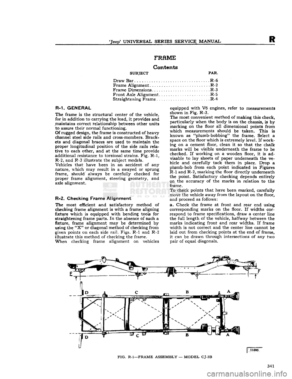
R-2.
Checking
Frame
Alignment
anci
proceed
as
follows:
The
most efficient
and
satisfactory method
of a.
Check
the
frame
at
front
and
rear
end
using
checking
frame alignment
is
with
a
frame aligning corresponding marks
on the
floor.
If
widths
cor-
fixture
which
is
equipped with bending
tools
for
respond
to
frame specifications, draw
a
center line
straightening frame parts. In the absence
of
such
a the
full
length
of
the vehicle, halfway
between
the
fixture,
frame
alignment
may be
determined
by
marks indicating front and
rear
widths.
If
frame
using the
"X"
or diagonal method of checking from width
is not
correct and
the
center line cannot
be
given points
on
each side
rail.
Figs.
R-1 and R-2
laid
out
from checking points
at the
end
of
frame,
illustrate
this method
of
checking
the
frame.
it
can
be
drawn through intersections
of
any
two
When
checking frame alignment
on
vehicles
pair
of
equal diagonals.
FIG.
R-1—FRAME
ASSEMBLY
—
MODEL
CJ-3B
341
Page 345 of 376
'Jeep'
UNIVERSAL
SERIES
SERVICE
MANUAL
s
SPRINGS
AND
SHOCK
ABSORBERS
Contents
SUBJECT
PAR. SUBJECT PAR.
Pivot Bolts S-3 Spring Removal S-4
Shock
Absorbers S-7 Spring Shackles S-2
Spring
Installation S-5 U-Shackles S-6
S-1.
GENERAL
Semielliptical
leaf springs are used for all models.
The
springs are hung longitudinally from the frame
side rails by means of brackets welded to the
rails.
All
axles are firmly attached to the springs by U-
bolts
(spring clips), spring saddles welded to the
underside of the axles, and spring plates under the
springs.
Early
model DJ-5 and DJ-6 front axles (I beam) are attached to the springs with conven
tional
bolts
and spring plates. Spring center
bolts
are
inserted in the axle spring saddles to prevent
shifting of the axle.
All
front springs, except as noted below, are provided with shackles at the front ends of the springs
and
pivot
bolts
at the
rear
ends of the springs. Model CJ-5 up to
Serial
No. 44437 and Model
CJ-6
up to
Serial
No. 11981 are provided with shackles at the
rear
ends of the front springs, and
pivot
bolts
at the front ends.
Note:
Models
CJ-5A
and
CJ-6A
are equipped with
the two
stage
type front and
rear
spring.
All
rear
springs are provided with shackles at the
rear
end and pivot
bolts
at the front end.
Springs
should be examined periodically for broken
or
shifted leaves,
loose
or missing rebound clips,
angle of spring shackles, and position of springs
on the saddles. Springs with shifted leaves do not have their normal strength. Missing rebound clips may permit the spring leaves to fan out or break
on rebound. Broken leaves may make the vehicle
hard
to handle or permit the axle to shift out of
line.
Weakened springs may break causing difficulty
in
steering. Spring attaching clips or
bolts
must be tight. It is
suggested
that they be checked at each
vehicle inspection and torqued 45 to 55 lb-ft. [6,2 a 7,6 kg-m.].
S-2.
Spring Shackles
Rubber-bushed
shackles are provided on all current
production vehicles. The steel-backed rubber (silent bloc) bushings are pressed into the spring
eyes
and mounting brackets. The shackle
bolts
tighten the side plates against the inner steel back
ing of the bushings. Oscillation of the springs is
taken in the rubber bushings.
All
vehicles produced before early 1957 were
equipped with U-shackles and threaded core bush-
*3(
21-
to It is
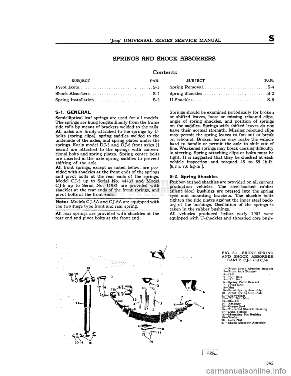
FIG-
S-1—FRONT SPRING
AND SHOCK ABSORBER
EARLY
CJ-5 and CJ-6
1—
Front
Shock Absorber
Bracket
2—
Front
Axle
Bumper
3—
Bolt
4—
"U"
Bolt
5—
"U"
Bolt
6—
Spring
Pivot
Bracket
7—
Pivot
Bolt
8—
Nut
9—
Front
Spring
Assembly
10—Front
Spring
Clip
Plate
11
—Lockwasher
12—
"U"
Bolt Nut
13—
Shackle
14—
Retainer
15—
Grease
Seal
16—
Threaded
Shackle
Bushing
17—
Lube
Fitting
18—
Mounting
Pin Bushing
19—
Washer
20—
Lock
Nut
21—
Shock
Absorber Assembly
1190L
345
Page 361 of 376
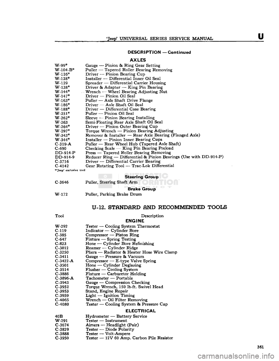
'Jeep*
UNIVERSAL
SERIES
SERVICE
MANUAL
U
DESCRIPTION
—
Continued
AXLES
W-99* Gauge — Pinion & Ring
Gear
Setting
W-104-B* Puller — Tapered Roller Bearing Removing
W-126* Driver — Pinion Bearing Cup
W-128* Installer — Differential Inner Oil Seal W-129 Spreader — Differential
Carrier
Housing
W-138* Driver & Adapter —
King
Pin Bearing
W-144* Wrench — Wheel Bearing Adjusting Nut W-147* Driver — Pinion Oil Seal W-163* Puller
—-
Axle Shaft Drive Flange
W-186* Driver — Axle Shaft Oil Seal
W-188* Driver — Differential Case Bearing W-251* Puller — Pinion Oil Seal
W-262*
Sleeve
— Pinion Bearing Installing
W-263
Semi-Floating
Rear
Axle Shaft Oil Seal W-264* Driver — Pinion Outer Bearing Cup
W-297* Torque Wrench — Pinion Bearing Adjusting W-343* Remover
85
Installer —
Rear
Axle Bearing (Flanged Axle)
W-344* Installer — Pinion Inner Bearing Cups
C-319-A
Puller —
Rear
Wheel Hub (Tapered Axle Shaft)
C-690 Checking Scale —
King
Pin Bearing Preload DD-914-P Press — Tapered Roller Bearing Removing
DD-914-9 Reducer Ring — Differential & Pinion Bearings (Use with DD-914-P)
C-3
716 Driver — Differential
Carrier
Bearing C-4142
Gear
Rotating Tool —
Trac-Lok
Differential
**Jeep*
exclusive
tool
Steering
Group
C-3646 Puller, Steering Shaft Arm
Brake
Group
W-172 Puller, Parking Brake Drum
U-12.
STflNDfiRD
AND
RECOMMENDED
TOOLS
Tool
Description
ENGINE
W-292
Tester — Cooling
System
Thermostat
C-119 Indicator — Cylinder Bore C-385 Compressor — Piston Ring
C-647 Fixture — Spring Testing
C-823
Hone
— Cylinder Bore Refinishing
C-3012 Reamer — Cylinder Ridge
C-3250 Pliers — Radiator fis Heater
Hose
Wire Clamp
C-3411
Gauge — Pressure & Vacuum
C-3422-A Compressor — E-type Valve Spring
C-3501
Hone
— Cylinder
Deglazing
C-3514
Flusher — Cooling
System
C-3886 Fixture — Carburetor Holding C-3896-A Tachometer — Portable
C-3943 Gauge — Compression Checking
C-3952 Torque Wrench, 150
lb-ft.
Swivel Head C-3953 Stand, Engine Repair
C-3959 Light — Ignition Timing
C-4065 Wrench — Oil Filter Removing
C-4080 Tester — Cooling
System
fig
Pressure Cap
ELECTRICAL
40B Hydrometer — Battery Service
W-291 Tester — Instrument
C-3674
Aimers —
Headlight
(Pair)
C-3829 Tester —
Diode
Polarity
C-3888 Tester — Volt-Ampere C-3950 Tester — 12V 60 Amp. Carbon Pile Resistor 361
Page 362 of 376
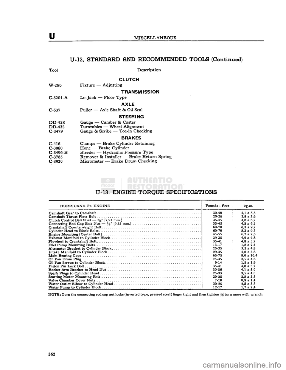
u
MISCELLANEOUS
U-12.
STANDARD
AND
RECOMMENDED TOOLS
(Continued)
Tool
Description
CLUTCH
W-296 Fixture — Adjusting
TRANSMISSION
C-3201
- A
Lo-Jack
— Floor Type
AXLE
C-637 Puller — Axle Shaft & Oil Seal
STEERING
DD-428 Gauge — Camber & Caster
DD-435 Turntables — Wheel Alignment C-3479 Gauge & Scribe — Toe-in Checking
BRAKES
C-416 Clamps — Brake Cylinder Retaining C-3080 Hone — Brake Cylinder
C-3496-B Bleeder — Hydraulic Pressure Type C-3785 Remover & Installer — Brake Return Spring
C-3920 Micrometer — Brake Drum Checking
U-13.
ENGINE TORQUE SPECIFICATIONS HURRICANE
F4
ENGINE
Pounds - Feet
kg-m.
30-40
4,1
a
5,5
Camshaft
Thrust Plate Bolt
20-26
2,8
a
3,6
Clutch
Control
Ball
Stud — [7,93 mm.]
35-45
4,8
a
6,2
Connecting Rod Cap Bolt Nut — y8" [9,53 mm.|
35-45
4,8
a
6,2
60-70
8,3
a
9,7
Cylinder
Head to Block Bolts
60-70
8,3
a
9,7
45-55
6,2
a
7,6
29-35
4,0
a
4,8
Flywheel
to Crankshaft Bolt. 35-41
4,8
a
5,7
Fuel
Pump Mounting Bolts 13-17 1,8
a
2,4
Alternator Bracket to Cylinder Block.
25-35
3,5
a
4,8
29-35
4,0
a
4,8
Main
Bearing
Caps.
.
65-75
9,0
a
10,4
Oil
Pan
Drain
Plug
25-35
3,5
a
4,8
9-14 1,2
a
1,9
Piston Pin
Lock
Bolt 35-41
4,8
a
5,7
30-36
4,1
a
5,0
Spark
Plugs to Cylinder Head
25-33
3,5
a
4,6
Starting Motor Mounting Bolt.
20-25
2,8
a
3,5
7-10 0,9
a
1,4
Water
Outlet Elbow to Cylinder Head
20-25
2,8
a
3,5
Water
Pump to Cylinder Block 12-17
1,7
a
2,4
NOTE:
Turn
the connecting rod cap nut locks (inverted type, pressed
steel)
finger
tight
and then
tighten
% turn more with wrench
362
Page 364 of 376
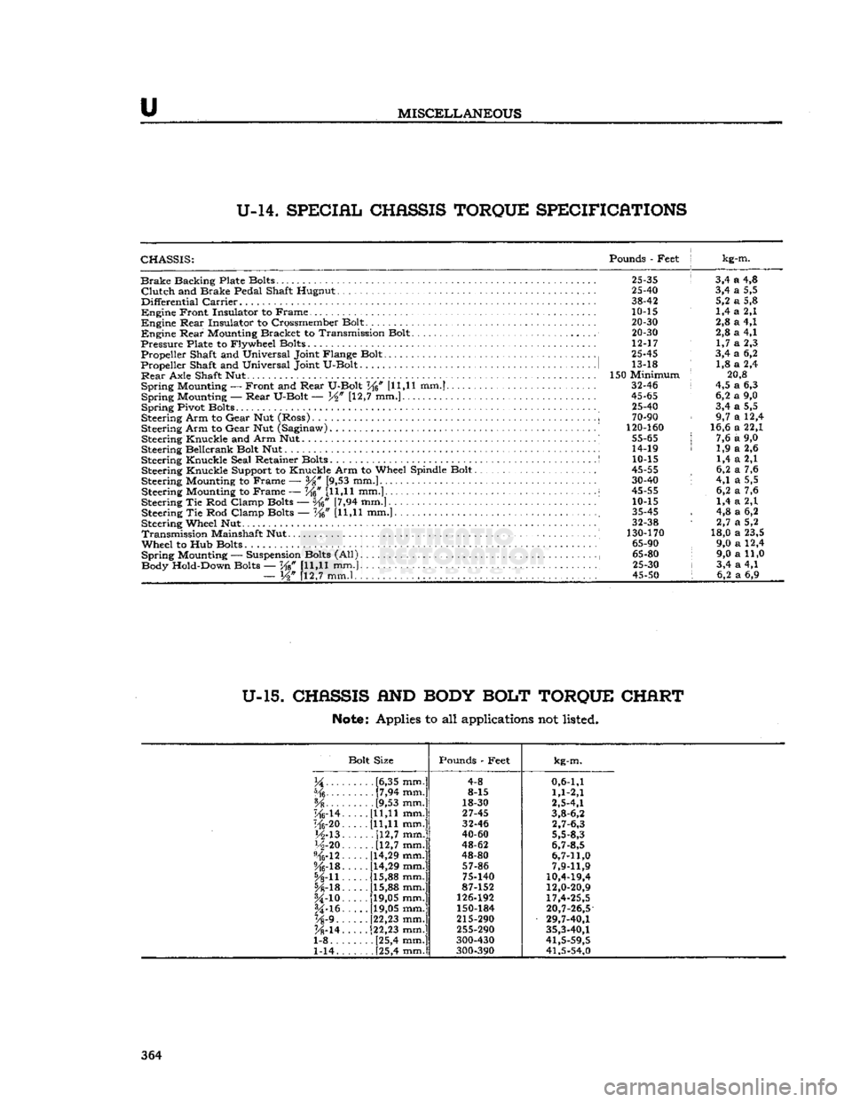
u
MISCELLANEOUS
U-14.
SPECIAL
CHASSIS
TORQUE
SPECIFICATIONS
CHASSIS:
Pounds
-
Feet
j kg-m.
Brake
Backing Plate Bolts.
25-35 ! 3,4 a 4,8
Clutch
and
Brake Pedal Shaft Hugnut
25-40 3,4 a 5,5
Differential
Carrier
38-42 5,2 a 5,8
Engine
Front Insulator
to
Frame.
10-15 1,4 a 2,1
Engine
Rear
Insulator
to
Crossmember Bolt.
. . ... 20-30 2,8 a 4,1
Engine
Rear
Mounting Bracket
to
Transmission Bolt.
20-30 2,8 a 4,1
Pressure
Plate
to
Flywheel Bolts
12-17 1,7 a 2,3
Propeller Shaft
and
Universal Joint Flange Bolt
25-45 3,4 a 6,2
Propeller Shaft
and
Universal Joint U-Bolt
1 13-18 : 1,8 a 2,4
Rear
Axle Shaft
Nut 150
Minimum
; 20,8
Spring
Mounting
—
Front
and
Rear
U-Bolt
V^n [11,11 mm.] 32-46 i 4,5 a 6,3
Spring
Mounting —-
Rear
U-Bolt
— [12,7 mm.] 45-65 6,2 a 9,0
Spring
Pivot Bolts
." 25-40 3,4 a 5,5
Steering Arm
to
Gear
Nut
(Ross)
..
i
70-90 9,7 a 12,4
Steering Arm
to
Gear
Nut
(Saginaw)
' 120-160 16,6 a 22,1
Steering Knuckle
and
Arm Nut..........
55-65 j 7,6 a 9,0
Steering Bellcrank Bolt
Nut 14-19 < 1,9 a 2,6
Steering Knuckle Seal Retainer Bolts
S 10-15 1,4 a 2,1
Steering Knuckle Support
to
Knuckle Arm
to
Wheel Spindle Bolt
45-55 , 6,2 a 7,6
Steering Mounting
to
Frame
—
Y%
[9,53 mm.] 30-40 '• 4,1 a 5,5
Steering Mounting
to
Frame
— W [11,11
mm.]...
i 45-55 6,2 a 7,6
Steering
Tie Rod
Clamp Bolts
— [7,94 mm.] 10-15 1,4 a 2,1
Steering
Tie Rod
Clamp Bolts
— Ke" [U,H mm.] ; 35-45 , 4,8 a 6,2
Steering Wheel
Nut 32-38 1 2,7 a 5,2
Transmission
Mainshaft
Nut 130-170 18,0 a 23,5
Wheel
to Hub
Bolts
65-90 9,0 a 12,4
Spring
Mounting
—
Suspension Bolts
(All) , 65-80 9,0 a 11,0
Body Hold-Down Bolts
— W [11,11 mm.} 25-30 i 3,4 a 4,1
—
W [12,7 mm.l , . . 45-50 I 6,2 a 6,9
U-15.
CHASSIS
AND
BODY
BOLT
TORQUE
CHART
Note:
Applies to all applications not listed.
Bolt Size Pounds
-
Feet
kg-m.
.....
[6,35 mm.] 4-8
0,6-1,1
[7,94 mm.] 8-15
1,1-2,1
[9,53 mm.] 18-30
2,5-4,1
"Mrl4.
[11,11 mm.]
27-45
3,8-6,2
116-20. [11,11 mm.] 32-46
2,7-6,3
M-13.
[12,7
mm.]
40-60
5,5-8,3
H-20
[12,7
mm.]
48-62
6,7-8,5
%-12.
[14,29 mm.]
48-80
6,7-11,0
%-lB.
[14,29 mm.]
57-86
7,9-11,9
5A-n. [15,88 mm.]
75-140
10,4-19,4
[15,88 mm.] 87-152
12,0-20,9
U-io.
[19,05 mm.]
126-192
17,4-25,5
§4-16.
[19,05 mm.]
150-184
20,7-26,5
Vs'9..
[22,23 mm.]
215-290
29,7-40,1
K-14.
[22,23 mm.]
255-290
35,3-40,1
1-8 [25,4 mm.] 300-430
41,5-59,5
1-14. . [25,4 mm.]
300-390 41,5-54,0 364
Page 371 of 376
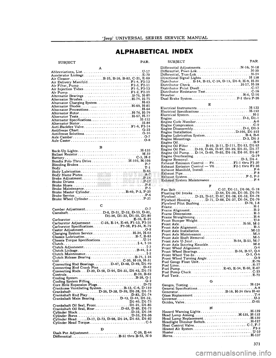
'Jeep'
UNIVERSAL
SERIES SERVICE
MANUAL
ALPHABETICAL INDEX
SUBJECT PAR.
SUBJECT
PAR.
Abbreviations,
List
U-17 Accelerator Linkage E-70
Air
Cleaner B-25, B-26, B-82, C-21, E-69
Air
Delivery Manifold Fl-4, F2-12
Air
Filter, Pump • F2-3, F2-11
Air
Injection Tubes Fl-5, F2-13
Air
Pump Fl-2, F2-10
Alternator Bearings B-76, H-80
Alternator Brushes H-74, H-75
Alternator Charging System •
•
H-63
Alternator
Diodes
H-69, H-85
Alternator Precautions H-64 Alternator Rotor H-76, H-79
Alternator Tests H-67, H-77 Alternator Specifications H-l 52
Alternator Stator H-84
Anti-Backfire
Valve Fl-6, F2-14
Antifreeze
Chart
• G-22 Antifreeze
Solutions
- G-16
Axle Camber O-l
Axle Caster 0-8
Back-Up
Lights H-135
Ballast
Resistor. H-32 Battery C-3, H-2 Bendix Folo-Thru Drive H-105, H-106
Bleeding Brakes P-7
Body T-l Body Lubrication. B-65 Body Name Plates ' A-7
Brake
Adjustment P-14
Brake
Drums. • .P-17
Brake
Hoses
P-8
Brake
Maintenance . P-5
Brake
Master Cylinder B-40, P-2, P-20
Brake
Service P-6
Brake
Wheel Cylinder • P-21
Camber
Adjustment 0-7
Camshaft D-6, D-51, D-52, D-53, D-81, Dl-26, Dl-33, Dl-55, Dl-80
Carburetor
E-10, E-25
Carburetor
Adjustment C-25, E-14, E-40,
Fl-13,
F2-16
Carburetor
Specifications .Fl-38, F2-34, E-79
Caster
Adjustment 0-8
Charging
System Service. .H-34, H-63
Chassis
Lubrication B-7, B-83
Chassis
Torque Specifications U-14
Clutch
1-4, MO
Clutch
Adjustment 1-3
Clutch
Linkage B-44, 1-3
Clutch
Maintenance .. 1-2
Clutch
Release Bearing B-74, 1-25
Coil
C-20, H-19, H-31 Connecting Rod Bearings D-47, D-48, D-49, Dl-49 Connecting Rod
Crank
Pins D-42
Connecting Rods... .D-20, D-50, D-95, Dl-31, Dl-45, Dl-75
Controls B-59, B-62
Cooling System B-28, G-l Cooling System Filling G-2
Core
Hole Expansion Plugs D-72
Crankcase
Ventilating System B-13, C-6, D-110
Crankshaft
D-26, D-38, D-39, Dl-38, Dl-73
Crankshaft
End Play. D-83, Dl-74
Crankshaft
Main Bearing D-43, D-44, Dl-32, Dl-40, Dl-73
Crankshaft
Oil Seal, Front Dl-21, Dl-85
Crankshaft
Oil Seal, Rear D-63, D-85, Dl-72
Cylinder
Block D-32, Dl-34
Cylinder
Bores D-35, Dl-36
Cylinder
Head D-17, D-73, D-98, Dl-24, Dl-63, Dl-82
Cylinder
Head Torque. C-5
Dash Pot Adjustment C-26, E-44
Differential B-51 thru B-53, N-9 Differential Adjustments N-16, N-18
Differential, Powr-Lok N-20
Differential,
Trac-Lok
N-24
Directional Signal Lights. . H-138
Distributor B-14, B-15, C-10, D-13, Dl-9, H-9, H-20 Distributor Check H-l7, H-28
Distributor Point Dwell C-17 Distributor Resistance Test C-16
Drawbar
.R-6, U-16
Dual
Brake System P-l thru P-26
Electrical
Instruments H-l22
Electrical
Specifications .H-l52
Electrical
System H-l Engine .
..D-l,
Dl-1
Engine Code Number A-6
Engine Compression .
.
C-9 Engine Disassembly . • .D-6, Dl-5 Engine Installation D-105, Dl-102
Engine Lubrication System B-4, B-6 Engine Mountings D-3, Dl-3
Engine Oil B-9
Engine Oil Filter B-10, B-ll,
D-lll,
Dl-13, Dl-93
Engine Oil Pan D-l9, D-66, D-97, Dl-29, Dl-51, Dl-77 Engine Oil Pump. . .D-14, D-65, D-93, Dl-19, Dl-50, Dl-87
Engine Overheating. G-l9 Engine Removal D-5, Dl-4.
Exhaust
Emission Control — F4 Fl-1 thru Fl-30
Exhaust
Emission Control — V6 F2-1 thru F2-36
Exhaust
Manifold, Install F-6
Exhaust
Pipe -
•
F-8
Exhaust
System F-2, F-3
Exhaust
System Maintenance F-4
Fan
Belt C-27, Dl-11, Dl-96, G-18
Floating Oil Intake. D-64, Dl-30, Dl-50, Dl-76 Flywheel D-25, D-67, D-87, Dl-28, Dl-52, Dl-78
Flywheel Housing. D-71, D-88, Dl-27, Dl-54, Dl-79
Flywheel Pilot Bushing D-70, 1-8
Frame
R-l
Frame
Alignment. R-2
Frame
Dimensions R-3
Frame
Straightening R-4
Front
Bumper Weight. • U-9
Front
Axle B-50, M-2
Front
Axle Alignment R-5
Front
Axle Installation • M-12
Front
Axle Maintenance M-3
Front
Axle Shaft Removal M-5
Front
Axle U-Joint B-54, B-55, M-7
Front
Axle Steering Knuckle M-&
Front
Wheel Alignment 0-4
Front
Wheel Bearings B-56, B-57, Q-4
Front
Wheel Toe-in 0-5, 0-6
Front
Wheel Turning Angle 0-9
Fuel
Gauge Float Unit F-76
Fuel
Lines - E-77
Fuel
Pump E-45, E-54, E-60, E-67
Fuel
Pump Check C-23
Fuel
Tank
E-72
G
Gauges, Testing H-l24
General
Specifications A-8
Generator B-16, H-34 thru H-40
Glass
Replacement • T-4
Governor. . .
•.
• U-3
Guides, Valve D"61
H
Hazard
Warning Lights H-139
Head Lamp Aiming H-131, H-132 Head Lamp Replacement H-130
Headlight Dimmer Switch H-l
2
7
Heat Control Valve C-7, F-7 Heated Air System • •
•
F2-2
Heater U-10
Horns.....
....H-137 371
Page 372 of 376
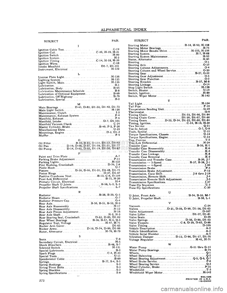
ALPHABETICAL
INDEX
SUBJECT
PAR.
SUBJECT
PAR.
Ignition Cable Test C-l9 Ignition
Coil
C-20, H-19, H-31
Ignition Switch H-89 Ignition System H-3
Ignition
Timing
C-14, H-18, H-30 Ignition Wires C-18
Intake Manifold '." Dl-7, Dl-101
Instrument, Electrical H-122
L
License Plate Light H-l36
Lighting
System H-l25
Light
Switch, Main . H-l 26
Lubrication
B-l
Lubrication,
Body B-65
Lubrication
Maintenance Schedule B-8
Lubrication
of Optional Equipment B-69
Lubrication,
Off Highway B-79
Lubrication,
Special. B-2
M
Main
Bearings D-43, D-82, Dl-32, Dl-42, Dl-73
Main
Light Switch. H-l26
Maintenance, Clutch 1-2 Maintenance, Exhaust System.,
-
F-4
Manifold, Exhaust -F-6 Manifold, Intake D-7, Dl-101
Manifold Vacuum Check. .C-24 Master Cylinder, Brake B-40, P-2, P-20
Miscellaneous Data U-16 Mountings, Engine • • •
-
D-3, Dl-3
Muffler. F-9
O
Oil
Filter B-10, B-ll,
D-lll,
Dl-13, Dl-93
Oil
Pan D-19, D-66, D-97, Dl-29, Dl-51, Dl-77
Oil
Pump. D-14, D-65, D-93, Dl-19, Dl-50, Dl-87
P
Paint and
Trim
Plate • • A-7
Parking
Brake Adjustment P-ll
Parking
Lights H-133
Pilot Bushing, Crankshaft D-70, 1-8
Pintle Hook U-7
Pistons D-20, D-95, Dl-31, Dl-48, Dl-75 Piston Rings. • • •
•
D-37, Dl-47 Positive Crankcase Vent. B-13, C-6, D-110
Powr-Lok
Differential B-72, N-20
Primary
Circuit,
Electrical H-4 Propeller Shaft U-Joints .B-58, L-2, L-3 Propeller Shaft Specifications <:' L-7
R
Radiator
B-28, B-29, G-5
Radiator
Hoses. G-7
Radiator
Pressure Cap G-4
Rear
Axle. B-50, B-51, B-52, N-9
Rear
Axle Reassembly • N-l
7
Rear
Axle Disassembly N-l
2
Rear
Axle Pinion Adjustment N-l6
Rear
Axle Shaft N-2, N-3
Rear
Bearing Seal, Crankshaft D-63, D-85, Dl-62
Rear
Wheel Bearings B-56, B-57, N-4, Q-3
Regulator Test, Voltage H-47, H-71
Rocker
Arm Cover.. . Dl-65
Rocker
Arms D-16, D-74, D-99, Dl-60 Rotor, Alternator H-76, H-79
S
Seats
• T-8 Secondary
Circuit,
Electrical H-5
Shock Absorbers B-48, S-7
Solenoid Switch. H-l21 Special Lubricants B-2
Spark
Plugs C-4, H-33
Special Tools • U-ll
Speedometer
Cable B-60 Springs B-77, S-4, S-5
Spring
Bushings S-2
Spring
Pivot Bolts S-3
Spring
Shackles S^2
Spring
Specifications S-8 372 Starting Motor B-18, H-92, H-108
Starting Motor Bearings B-75
Starting Motor Bendix Drive H-105, H-106
Starting System H-7, H-88
Starting System Maintenance H-93 Stator, Alternator H-84
Steering • • •
•
O-l
Steering Arm P-10
Steering Column Adjustments 0-4
Steering Column and Wheel Service O-20 Steering Gear. . B-27, 0-22
Steering Gear Adjustment 0-5
Steering Gear Function 0-2
Steering Knuckle. B-27, M-8 Steering Linkage 0-14
Stop
Light Switch H-128
Switch, Heater U-10 Switch, Ignition H-89
Switch, Wiper Motor H-142
T
Tail
Light . H-134
Tail
Pipe F-10 Temperature Sending Unit G-10
Thermostat G-9
Timing
Chain Dl-22, Dl-66, Dl-84
Timing
Chain Cover Dl-20, Dl-67, Dl-86
Timing
Gears D-22, D-54, Dl-22, Dl-66, Dl-84
Timing,
Ignition. C-14, H-18, H-30
Tire
Service . •
•
Q-l
1
Toe-in Adjust 0-7, 0-8 Tools, Special. . .
........
U-ll Torque Specifications, Chassis U-14
Torque Specifications, Engine .U-13
Top,
Canvas. T-5
Trac-Lok
Differential N-24
Transfer
Case B-36, K-1
Transfer
Case Reassembly K-6
Transfer
Case Disassembly K-3
Transfer
Case Linkage - K-8
Transfer
Case Removal K-2 Transmission and Transfer Case. B-30, J-7 Transmission —
3-Speed
B-37, B-38, J-l
Transmission —
4-Speed
... J-20
Transmission Brake P-4 Transmission Brake Adjustment P-l
2
Transmission,
Cane Shift .J-8 thru J-19
Transmission,
Remote Shift J-4
Transmission Remote Shift Adjustment J-3
Transmission Specifications
-
J-27
Tune-Up
Sequence
C-2
Tune-Up
Specifications C-30
U
U-Joint, Front Axle . . B-54, B-55, M-7
U-Joint, Propeller Shaft B-58, L-l
Vacuum
C-24 Valves D-21, D-56, D-90, Dl-56, Dl-63
Valve
Adjustment D-107
Valve
Lifter Dl-57, Dl-81
Valve
Seats
D-59
Valve
Springs .D-56, D-90, Dl-63
Valve
Tappets C-8, D-29, D-62, D-80
Valve
Timing D-109
Vehicle Description A-2
Vehicle Identification A-3
Vehicle Serial Number. A-5
Vibration
Damper D-l2, D-96, Dl-17, Dl-70 Voltage Regulator. H-41, H-71
W
Water Pump G-ll thru G-15
Water Pump Bearings B-74
Wheels Q-l
Wheel Balancing Q-2 Wheel Bearing Adjustment Q-5, Q-6, Q-7
Wheel Brake Service P-6 Wheel Bearing Service Q-3
Wheel Cylinder, Brake P-21 Windshield T-3 Windshield Wiper Motor . .H-142
SM-1046
PRINTED
IN U.S.A.
110-CH6M