steering wheel JEEP CJ 1953 Owner's Guide
[x] Cancel search | Manufacturer: JEEP, Model Year: 1953, Model line: CJ, Model: JEEP CJ 1953Pages: 376, PDF Size: 19.96 MB
Page 362 of 376

u
MISCELLANEOUS
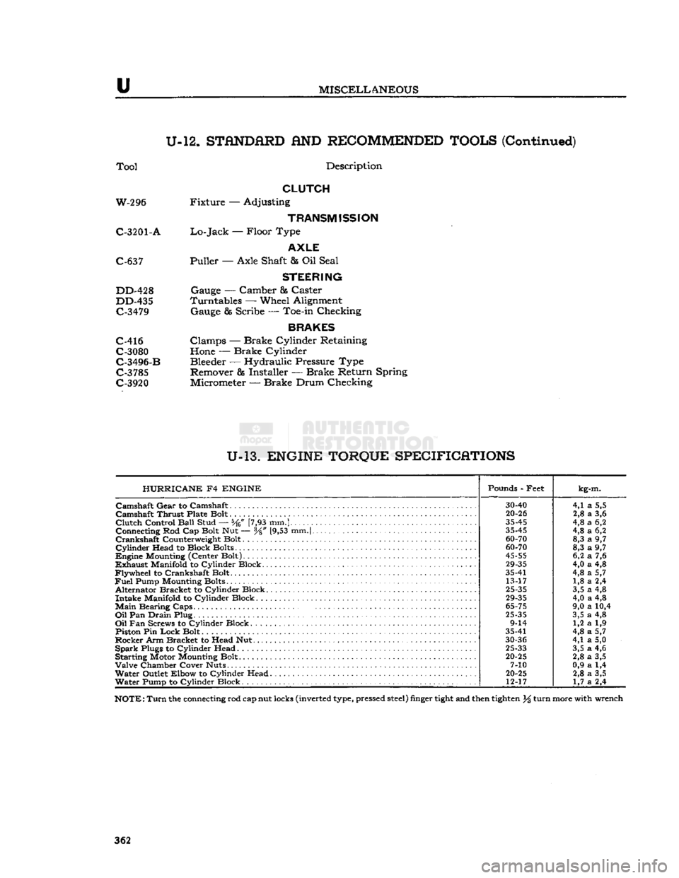
U-12.
STANDARD
AND
RECOMMENDED TOOLS
(Continued)
Tool
Description
CLUTCH
W-296 Fixture — Adjusting
TRANSMISSION
C-3201
- A
Lo-Jack
— Floor Type
AXLE
C-637 Puller — Axle Shaft & Oil Seal
STEERING
DD-428 Gauge — Camber & Caster
DD-435 Turntables — Wheel Alignment C-3479 Gauge & Scribe — Toe-in Checking
BRAKES
C-416 Clamps — Brake Cylinder Retaining C-3080 Hone — Brake Cylinder
C-3496-B Bleeder — Hydraulic Pressure Type C-3785 Remover & Installer — Brake Return Spring
C-3920 Micrometer — Brake Drum Checking
U-13.
ENGINE TORQUE SPECIFICATIONS HURRICANE
F4
ENGINE
Pounds - Feet
kg-m.
30-40
4,1
a
5,5
Camshaft
Thrust Plate Bolt
20-26
2,8
a
3,6
Clutch
Control
Ball
Stud — [7,93 mm.]
35-45
4,8
a
6,2
Connecting Rod Cap Bolt Nut — y8" [9,53 mm.|
35-45
4,8
a
6,2
60-70
8,3
a
9,7
Cylinder
Head to Block Bolts
60-70
8,3
a
9,7
45-55
6,2
a
7,6
29-35
4,0
a
4,8
Flywheel
to Crankshaft Bolt. 35-41
4,8
a
5,7
Fuel
Pump Mounting Bolts 13-17 1,8
a
2,4
Alternator Bracket to Cylinder Block.
25-35
3,5
a
4,8
29-35
4,0
a
4,8
Main
Bearing
Caps.
.
65-75
9,0
a
10,4
Oil
Pan
Drain
Plug
25-35
3,5
a
4,8
9-14 1,2
a
1,9
Piston Pin
Lock
Bolt 35-41
4,8
a
5,7
30-36
4,1
a
5,0
Spark
Plugs to Cylinder Head
25-33
3,5
a
4,6
Starting Motor Mounting Bolt.
20-25
2,8
a
3,5
7-10 0,9
a
1,4
Water
Outlet Elbow to Cylinder Head
20-25
2,8
a
3,5
Water
Pump to Cylinder Block 12-17
1,7
a
2,4
NOTE:
Turn
the connecting rod cap nut locks (inverted type, pressed
steel)
finger
tight
and then
tighten
% turn more with wrench
362
Page 364 of 376

u
MISCELLANEOUS
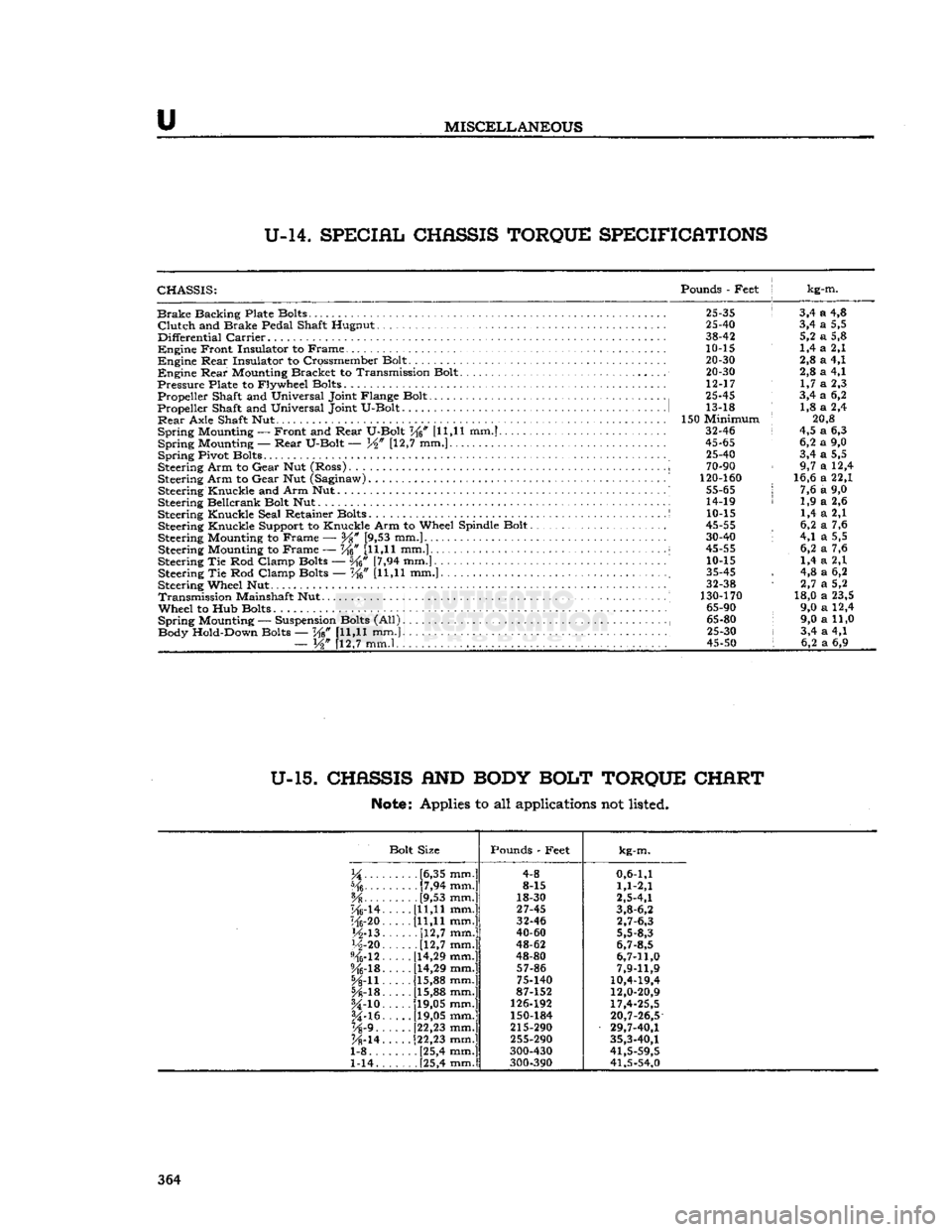
U-14.
SPECIAL
CHASSIS
TORQUE
SPECIFICATIONS
CHASSIS:
Pounds
-
Feet
j kg-m.
Brake
Backing Plate Bolts.
25-35 ! 3,4 a 4,8
Clutch
and
Brake Pedal Shaft Hugnut
25-40 3,4 a 5,5
Differential
Carrier
38-42 5,2 a 5,8
Engine
Front Insulator
to
Frame.
10-15 1,4 a 2,1
Engine
Rear
Insulator
to
Crossmember Bolt.
. . ... 20-30 2,8 a 4,1
Engine
Rear
Mounting Bracket
to
Transmission Bolt.
20-30 2,8 a 4,1
Pressure
Plate
to
Flywheel Bolts
12-17 1,7 a 2,3
Propeller Shaft
and
Universal Joint Flange Bolt
25-45 3,4 a 6,2
Propeller Shaft
and
Universal Joint U-Bolt
1 13-18 : 1,8 a 2,4
Rear
Axle Shaft
Nut 150
Minimum
; 20,8
Spring
Mounting
—
Front
and
Rear
U-Bolt
V^n [11,11 mm.] 32-46 i 4,5 a 6,3
Spring
Mounting —-
Rear
U-Bolt
— [12,7 mm.] 45-65 6,2 a 9,0
Spring
Pivot Bolts
." 25-40 3,4 a 5,5
Steering Arm
to
Gear
Nut
(Ross)
..
i
70-90 9,7 a 12,4
Steering Arm
to
Gear
Nut
(Saginaw)
' 120-160 16,6 a 22,1
Steering Knuckle
and
Arm Nut..........
55-65 j 7,6 a 9,0
Steering Bellcrank Bolt
Nut 14-19 < 1,9 a 2,6
Steering Knuckle Seal Retainer Bolts
S 10-15 1,4 a 2,1
Steering Knuckle Support
to
Knuckle Arm
to
Wheel Spindle Bolt
45-55 , 6,2 a 7,6
Steering Mounting
to
Frame
—
Y%
[9,53 mm.] 30-40 '• 4,1 a 5,5
Steering Mounting
to
Frame
— W [11,11
mm.]...
i 45-55 6,2 a 7,6
Steering
Tie Rod
Clamp Bolts
— [7,94 mm.] 10-15 1,4 a 2,1
Steering
Tie Rod
Clamp Bolts
— Ke" [U,H mm.] ; 35-45 , 4,8 a 6,2
Steering Wheel
Nut 32-38 1 2,7 a 5,2
Transmission
Mainshaft
Nut 130-170 18,0 a 23,5
Wheel
to Hub
Bolts
65-90 9,0 a 12,4
Spring
Mounting
—
Suspension Bolts
(All) , 65-80 9,0 a 11,0
Body Hold-Down Bolts
— W [11,11 mm.} 25-30 i 3,4 a 4,1
—
W [12,7 mm.l , . . 45-50 I 6,2 a 6,9
U-15.
CHASSIS
AND
BODY
BOLT
TORQUE
CHART
Note:
Applies to all applications not listed.
Bolt Size Pounds
-
Feet
kg-m.
.....
[6,35 mm.] 4-8
0,6-1,1
[7,94 mm.] 8-15
1,1-2,1
[9,53 mm.] 18-30
2,5-4,1
"Mrl4.
[11,11 mm.]
27-45
3,8-6,2
116-20. [11,11 mm.] 32-46
2,7-6,3
M-13.
[12,7
mm.]
40-60
5,5-8,3
H-20
[12,7
mm.]
48-62
6,7-8,5
%-12.
[14,29 mm.]
48-80
6,7-11,0
%-lB.
[14,29 mm.]
57-86
7,9-11,9
5A-n. [15,88 mm.]
75-140
10,4-19,4
[15,88 mm.] 87-152
12,0-20,9
U-io.
[19,05 mm.]
126-192
17,4-25,5
§4-16.
[19,05 mm.]
150-184
20,7-26,5
Vs'9..
[22,23 mm.]
215-290
29,7-40,1
K-14.
[22,23 mm.]
255-290
35,3-40,1
1-8 [25,4 mm.] 300-430
41,5-59,5
1-14. . [25,4 mm.]
300-390 41,5-54,0 364
Page 371 of 376

'Jeep'
UNIVERSAL
SERIES SERVICE
MANUAL
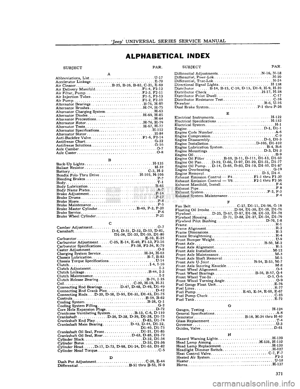
ALPHABETICAL INDEX
SUBJECT PAR.
SUBJECT
PAR.
Abbreviations,
List
U-17 Accelerator Linkage E-70
Air
Cleaner B-25, B-26, B-82, C-21, E-69
Air
Delivery Manifold Fl-4, F2-12
Air
Filter, Pump • F2-3, F2-11
Air
Injection Tubes Fl-5, F2-13
Air
Pump Fl-2, F2-10
Alternator Bearings B-76, H-80
Alternator Brushes H-74, H-75
Alternator Charging System •
•
H-63
Alternator
Diodes
H-69, H-85
Alternator Precautions H-64 Alternator Rotor H-76, H-79
Alternator Tests H-67, H-77 Alternator Specifications H-l 52
Alternator Stator H-84
Anti-Backfire
Valve Fl-6, F2-14
Antifreeze
Chart
• G-22 Antifreeze
Solutions
- G-16
Axle Camber O-l
Axle Caster 0-8
Back-Up
Lights H-135
Ballast
Resistor. H-32 Battery C-3, H-2 Bendix Folo-Thru Drive H-105, H-106
Bleeding Brakes P-7
Body T-l Body Lubrication. B-65 Body Name Plates ' A-7
Brake
Adjustment P-14
Brake
Drums. • .P-17
Brake
Hoses
P-8
Brake
Maintenance . P-5
Brake
Master Cylinder B-40, P-2, P-20
Brake
Service P-6
Brake
Wheel Cylinder • P-21
Camber
Adjustment 0-7
Camshaft D-6, D-51, D-52, D-53, D-81, Dl-26, Dl-33, Dl-55, Dl-80
Carburetor
E-10, E-25
Carburetor
Adjustment C-25, E-14, E-40,
Fl-13,
F2-16
Carburetor
Specifications .Fl-38, F2-34, E-79
Caster
Adjustment 0-8
Charging
System Service. .H-34, H-63
Chassis
Lubrication B-7, B-83
Chassis
Torque Specifications U-14
Clutch
1-4, MO
Clutch
Adjustment 1-3
Clutch
Linkage B-44, 1-3
Clutch
Maintenance .. 1-2
Clutch
Release Bearing B-74, 1-25
Coil
C-20, H-19, H-31 Connecting Rod Bearings D-47, D-48, D-49, Dl-49 Connecting Rod
Crank
Pins D-42
Connecting Rods... .D-20, D-50, D-95, Dl-31, Dl-45, Dl-75
Controls B-59, B-62
Cooling System B-28, G-l Cooling System Filling G-2
Core
Hole Expansion Plugs D-72
Crankcase
Ventilating System B-13, C-6, D-110
Crankshaft
D-26, D-38, D-39, Dl-38, Dl-73
Crankshaft
End Play. D-83, Dl-74
Crankshaft
Main Bearing D-43, D-44, Dl-32, Dl-40, Dl-73
Crankshaft
Oil Seal, Front Dl-21, Dl-85
Crankshaft
Oil Seal, Rear D-63, D-85, Dl-72
Cylinder
Block D-32, Dl-34
Cylinder
Bores D-35, Dl-36
Cylinder
Head D-17, D-73, D-98, Dl-24, Dl-63, Dl-82
Cylinder
Head Torque. C-5
Dash Pot Adjustment C-26, E-44
Differential B-51 thru B-53, N-9 Differential Adjustments N-16, N-18
Differential, Powr-Lok N-20
Differential,
Trac-Lok
N-24
Directional Signal Lights. . H-138
Distributor B-14, B-15, C-10, D-13, Dl-9, H-9, H-20 Distributor Check H-l7, H-28
Distributor Point Dwell C-17 Distributor Resistance Test C-16
Drawbar
.R-6, U-16
Dual
Brake System P-l thru P-26
Electrical
Instruments H-l22
Electrical
Specifications .H-l52
Electrical
System H-l Engine .
..D-l,
Dl-1
Engine Code Number A-6
Engine Compression .
.
C-9 Engine Disassembly . • .D-6, Dl-5 Engine Installation D-105, Dl-102
Engine Lubrication System B-4, B-6 Engine Mountings D-3, Dl-3
Engine Oil B-9
Engine Oil Filter B-10, B-ll,
D-lll,
Dl-13, Dl-93
Engine Oil Pan D-l9, D-66, D-97, Dl-29, Dl-51, Dl-77 Engine Oil Pump. . .D-14, D-65, D-93, Dl-19, Dl-50, Dl-87
Engine Overheating. G-l9 Engine Removal D-5, Dl-4.
Exhaust
Emission Control — F4 Fl-1 thru Fl-30
Exhaust
Emission Control — V6 F2-1 thru F2-36
Exhaust
Manifold, Install F-6
Exhaust
Pipe -
•
F-8
Exhaust
System F-2, F-3
Exhaust
System Maintenance F-4
Fan
Belt C-27, Dl-11, Dl-96, G-18
Floating Oil Intake. D-64, Dl-30, Dl-50, Dl-76 Flywheel D-25, D-67, D-87, Dl-28, Dl-52, Dl-78
Flywheel Housing. D-71, D-88, Dl-27, Dl-54, Dl-79
Flywheel Pilot Bushing D-70, 1-8
Frame
R-l
Frame
Alignment. R-2
Frame
Dimensions R-3
Frame
Straightening R-4
Front
Bumper Weight. • U-9
Front
Axle B-50, M-2
Front
Axle Alignment R-5
Front
Axle Installation • M-12
Front
Axle Maintenance M-3
Front
Axle Shaft Removal M-5
Front
Axle U-Joint B-54, B-55, M-7
Front
Axle Steering Knuckle M-&
Front
Wheel Alignment 0-4
Front
Wheel Bearings B-56, B-57, Q-4
Front
Wheel Toe-in 0-5, 0-6
Front
Wheel Turning Angle 0-9
Fuel
Gauge Float Unit F-76
Fuel
Lines - E-77
Fuel
Pump E-45, E-54, E-60, E-67
Fuel
Pump Check C-23
Fuel
Tank
E-72
G
Gauges, Testing H-l24
General
Specifications A-8
Generator B-16, H-34 thru H-40
Glass
Replacement • T-4
Governor. . .
•.
• U-3
Guides, Valve D"61
H
Hazard
Warning Lights H-139
Head Lamp Aiming H-131, H-132 Head Lamp Replacement H-130
Headlight Dimmer Switch H-l
2
7
Heat Control Valve C-7, F-7 Heated Air System • •
•
F2-2
Heater U-10
Horns.....
....H-137 371
Page 372 of 376

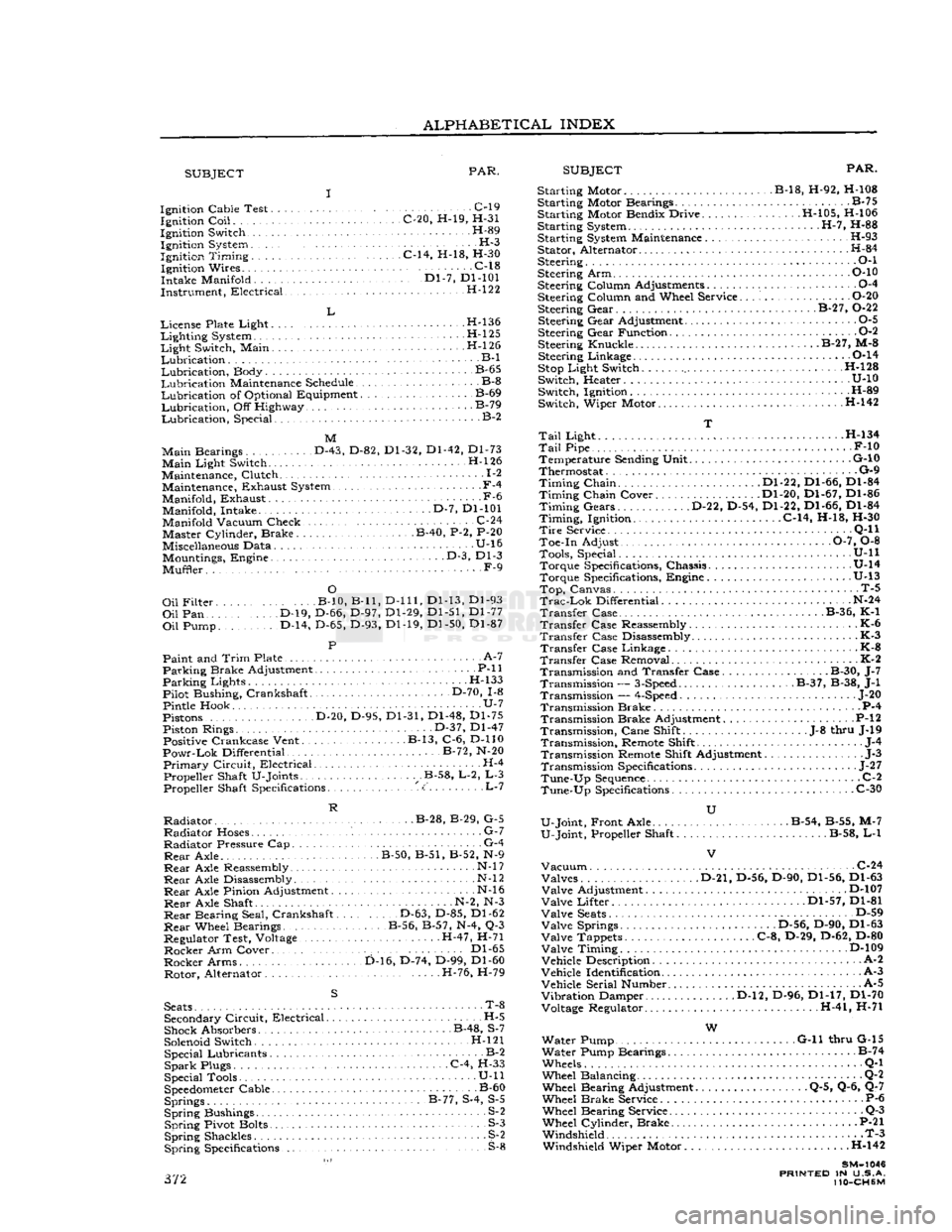
ALPHABETICAL
INDEX
SUBJECT
PAR.
SUBJECT
PAR.
Ignition Cable Test C-l9 Ignition
Coil
C-20, H-19, H-31
Ignition Switch H-89 Ignition System H-3
Ignition
Timing
C-14, H-18, H-30 Ignition Wires C-18
Intake Manifold '." Dl-7, Dl-101
Instrument, Electrical H-122
L
License Plate Light H-l36
Lighting
System H-l25
Light
Switch, Main . H-l 26
Lubrication
B-l
Lubrication,
Body B-65
Lubrication
Maintenance Schedule B-8
Lubrication
of Optional Equipment B-69
Lubrication,
Off Highway B-79
Lubrication,
Special. B-2
M
Main
Bearings D-43, D-82, Dl-32, Dl-42, Dl-73
Main
Light Switch. H-l26
Maintenance, Clutch 1-2 Maintenance, Exhaust System.,
-
F-4
Manifold, Exhaust -F-6 Manifold, Intake D-7, Dl-101
Manifold Vacuum Check. .C-24 Master Cylinder, Brake B-40, P-2, P-20
Miscellaneous Data U-16 Mountings, Engine • • •
-
D-3, Dl-3
Muffler. F-9
O
Oil
Filter B-10, B-ll,
D-lll,
Dl-13, Dl-93
Oil
Pan D-19, D-66, D-97, Dl-29, Dl-51, Dl-77
Oil
Pump. D-14, D-65, D-93, Dl-19, Dl-50, Dl-87
P
Paint and
Trim
Plate • • A-7
Parking
Brake Adjustment P-ll
Parking
Lights H-133
Pilot Bushing, Crankshaft D-70, 1-8
Pintle Hook U-7
Pistons D-20, D-95, Dl-31, Dl-48, Dl-75 Piston Rings. • • •
•
D-37, Dl-47 Positive Crankcase Vent. B-13, C-6, D-110
Powr-Lok
Differential B-72, N-20
Primary
Circuit,
Electrical H-4 Propeller Shaft U-Joints .B-58, L-2, L-3 Propeller Shaft Specifications <:' L-7
R
Radiator
B-28, B-29, G-5
Radiator
Hoses. G-7
Radiator
Pressure Cap G-4
Rear
Axle. B-50, B-51, B-52, N-9
Rear
Axle Reassembly • N-l
7
Rear
Axle Disassembly N-l
2
Rear
Axle Pinion Adjustment N-l6
Rear
Axle Shaft N-2, N-3
Rear
Bearing Seal, Crankshaft D-63, D-85, Dl-62
Rear
Wheel Bearings B-56, B-57, N-4, Q-3
Regulator Test, Voltage H-47, H-71
Rocker
Arm Cover.. . Dl-65
Rocker
Arms D-16, D-74, D-99, Dl-60 Rotor, Alternator H-76, H-79
S
Seats
• T-8 Secondary
Circuit,
Electrical H-5
Shock Absorbers B-48, S-7
Solenoid Switch. H-l21 Special Lubricants B-2
Spark
Plugs C-4, H-33
Special Tools • U-ll
Speedometer
Cable B-60 Springs B-77, S-4, S-5
Spring
Bushings S-2
Spring
Pivot Bolts S-3
Spring
Shackles S^2
Spring
Specifications S-8 372 Starting Motor B-18, H-92, H-108
Starting Motor Bearings B-75
Starting Motor Bendix Drive H-105, H-106
Starting System H-7, H-88
Starting System Maintenance H-93 Stator, Alternator H-84
Steering • • •
•
O-l
Steering Arm P-10
Steering Column Adjustments 0-4
Steering Column and Wheel Service O-20 Steering Gear. . B-27, 0-22
Steering Gear Adjustment 0-5
Steering Gear Function 0-2
Steering Knuckle. B-27, M-8 Steering Linkage 0-14
Stop
Light Switch H-128
Switch, Heater U-10 Switch, Ignition H-89
Switch, Wiper Motor H-142
T
Tail
Light . H-134
Tail
Pipe F-10 Temperature Sending Unit G-10
Thermostat G-9
Timing
Chain Dl-22, Dl-66, Dl-84
Timing
Chain Cover Dl-20, Dl-67, Dl-86
Timing
Gears D-22, D-54, Dl-22, Dl-66, Dl-84
Timing,
Ignition. C-14, H-18, H-30
Tire
Service . •
•
Q-l
1
Toe-in Adjust 0-7, 0-8 Tools, Special. . .
........
U-ll Torque Specifications, Chassis U-14
Torque Specifications, Engine .U-13
Top,
Canvas. T-5
Trac-Lok
Differential N-24
Transfer
Case B-36, K-1
Transfer
Case Reassembly K-6
Transfer
Case Disassembly K-3
Transfer
Case Linkage - K-8
Transfer
Case Removal K-2 Transmission and Transfer Case. B-30, J-7 Transmission —
3-Speed
B-37, B-38, J-l
Transmission —
4-Speed
... J-20
Transmission Brake P-4 Transmission Brake Adjustment P-l
2
Transmission,
Cane Shift .J-8 thru J-19
Transmission,
Remote Shift J-4
Transmission Remote Shift Adjustment J-3
Transmission Specifications
-
J-27
Tune-Up
Sequence
C-2
Tune-Up
Specifications C-30
U
U-Joint, Front Axle . . B-54, B-55, M-7
U-Joint, Propeller Shaft B-58, L-l
Vacuum
C-24 Valves D-21, D-56, D-90, Dl-56, Dl-63
Valve
Adjustment D-107
Valve
Lifter Dl-57, Dl-81
Valve
Seats
D-59
Valve
Springs .D-56, D-90, Dl-63
Valve
Tappets C-8, D-29, D-62, D-80
Valve
Timing D-109
Vehicle Description A-2
Vehicle Identification A-3
Vehicle Serial Number. A-5
Vibration
Damper D-l2, D-96, Dl-17, Dl-70 Voltage Regulator. H-41, H-71
W
Water Pump G-ll thru G-15
Water Pump Bearings B-74
Wheels Q-l
Wheel Balancing Q-2 Wheel Bearing Adjustment Q-5, Q-6, Q-7
Wheel Brake Service P-6 Wheel Bearing Service Q-3
Wheel Cylinder, Brake P-21 Windshield T-3 Windshield Wiper Motor . .H-142
SM-1046
PRINTED
IN U.S.A.
110-CH6M