steering wheel JEEP CJ 1953 User Guide
[x] Cancel search | Manufacturer: JEEP, Model Year: 1953, Model line: CJ, Model: JEEP CJ 1953Pages: 376, PDF Size: 19.96 MB
Page 278 of 376
M
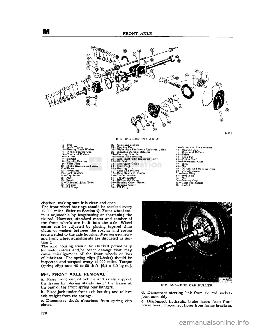
FRONT
AXLE
1— Nut
2—
Lock
Washer
3—
Bearing
Lock
Washer
4—
Wheel
Bearing Cup 5—
Cone
and Rollers
6—
Oil
Seal 7— Spindle
8— Spindle Bushing
9—
Filler
Plug
10—
Right
Knuckle and Arm
11— Shims
12— Pivot Pin
13—
Lock
Washer
14—
Cap
Screw
15— Nut
16—
Washer
17—
Universal
Joint Yoke
18—
Oil
Seal
19—
Oil
Slinger
FIG.
M-2—FRONT
AXLE
20—
Cone
and Rollers
21—
Bearing
Cup
22—
Right
Axle Shaft with Universal Joint
23—
Knuckle
Oil Seal Retainer
24— Housing Breather 25—
Front
Axle Housing
26—
Axle
Shaft with Universal Joint
27—
Oil
Seal
28—
Axle
Shaft Guide
29—
Shim
Pack
30—
Bearing
Cup
31—
Cone
and Rollers
32—
Ring
Gear
and Pinion
33—
Thrust
Washer
34—
Thrust
Washer
35—
Differential
Gears
36— Housing Cover Gasket
37— Housing Cover
38—
Fill
Plug 39—
Screw
and
Lock
Washer
40—
Bearing
Cup
41—
Cone
and Rollers
42— Shims
43—
Lock
Pin
44—
Pinion
Shaft
45—
Differential
Case
47— Bolts
48— Nut
49—
Oil
Seal and Backing Ring
50—
Thrust
Washer
51— Snap Ring
52— Stop Bolt
53— Nut 54—
Bearing
Cup
55—
Cone
and Rollers
56—
Gasket
checked, making sure it is clean and open.
The
front wheel bearings should be checked every
12,000
miles. Refer to Section Q. Front wheel toe-
in
is adjustable by lengthening or shortening the
tie rod. However, standard caster and camber of
the front
wheels
are built
into
the axle. Wheel
caster can be adjusted by placing tapered shim
plates or
wedges
between
the springs and spring
seats
welded to the axle housing. Steering
geometry
and
front wheel adjustments are discussed in Sec tion O.
The
axle housing should be checked periodically
for weld cracks and/or other damage that may cause misalignment of the front
wheels
or
loss
of lubricant. The spring clips (U-bolts) should be
inspected and torqued every
12,000
miles. Torque (spring clip) nuts 45 to 50 lb-ft. [6,2 a 6,9 kg-m.].
M-4. FRONT
AXLE
REMOVAL
a.
Raise front end of vehicle
arid
safely support the frame by placing stands under the frame at
the rear of the front spring rear hangers.
b. Place
jack
under front axle housing and relieve
axle
weight
from the springs.
c. Disconnect shock absorbers from spring clip plates.
FIG.
M-3—HUB
CAP
PULLER
d.
Disconnect steering link from tie rod socket-
joint assembly.
e. Disconnect hydraulic brake
hoses
from front
brake
lines. Disconnect
hoses
from frame brackets. 278
Page 280 of 376
M
FRONT
AXLE
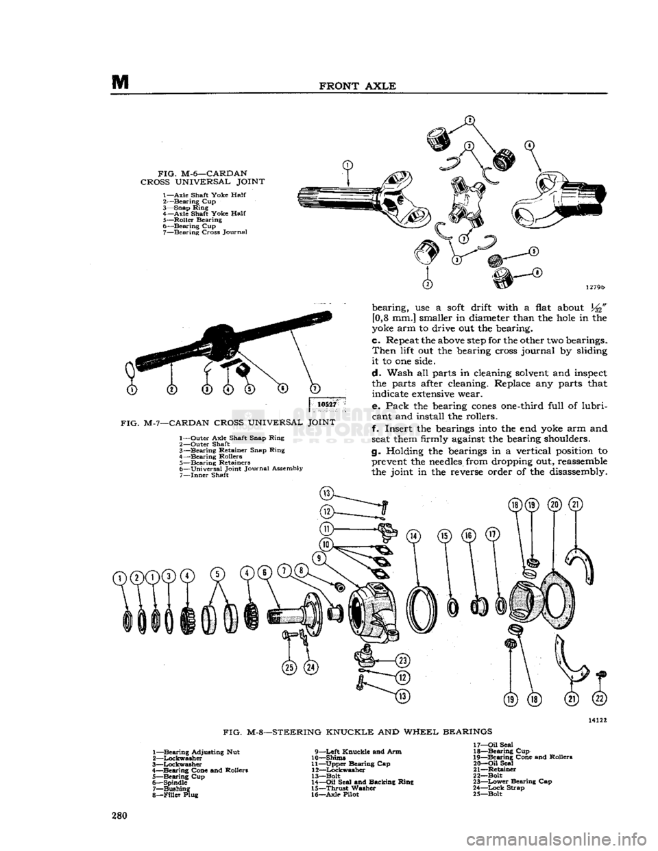
FIG.
M-6—CARDAN
CROSS
UNIVERSAL
JOINT
1—Axle
Shaft Yoke
Half
2-—Bearing Cup
3— Snap Ring 4— Axle Shaft Yoke
Half
5— Roller Bearing
6— Bearing Cup 7— Bearing Cross Journal
10527
FIG.
M-7—CARDAN
CROSS
UNIVERSAL
JOINT
1— Outer Axle Shaft Snap Ring
2— Outer Shaft
3— Bearing Retainer Snap Ring
4— Bearing Rollers 5— Bearing Retainers
6— Universal Joint Journal Assembly 7—
Inner
Shaft bearing, use a
soft
drift with a
flat
about
[0,8 mm.] smaller in
diameter
than the
hole
in the
yoke
arm to drive out the bearing.
c.
Repeat
the
above
step
for the
other
two
bearings.
Then
lift
out the
bearing
cross
journal by
sliding
it to one
side.
d. Wash all parts in
cleaning
solvent
and
inspect
the parts
after
cleaning.
Replace any parts
that
indicate
extensive
wear.
e. Pack the
bearing
cones
one-third
full of lubri
cant
and install the rollers.
f. Insert the
bearings
into
the end
yoke
arm and
seat
them
firmly
against
the
bearing
shoulders.
g.
Holding
the
bearings
in a vertical
position
to
prevent
the
needles
from
dropping
out,
reassemble
the joint in the
reverse
order of the
disassembly.
FIG.
M-8—STEERING KNUCKLE AND WHEEL BEARINGS
1— Bearing Adjusting Nut
2— Lockwasher
3— Lockwasher
4— Bearing Cone and Rollers 5— Bearing Cup
6— Spindle 7— Bushing
8—
Filler
Plug 9—Left Knuckle and Arm
10— Shims
11— Upper Bearing Cap 12— Lockwasher
13—Bolt
14—
Oil
Seal and Backing Ring
15—
Thrust
Washer
16— Axle Pilot 17—
Oil
Seal
18— Bearing Cup
19— Bearing Cone and Rollers
20—
Oil
Seal
21— Retainer
22— Bolt
23—
Lower
Bearing Cap
24—
Lock
Strap
25— Bolt 280
Page 281 of 376
'Jeep'
UNIVERSAL
SERIES
SERVICE
MANUAL
M
If
the joint binds when assembled, tap the yoke
lightly to relieve any pressure on the bearings at the end of the
journal.
M-8-
Steering
Knuckle
Service
The
steering knuckle pins pivot on tapered roller
bearings. Replacement of
these
bearings requires
removal
of the hub and brake drum assembly,
wheel bearings, axle shaft, spindle, steering tie rod,
and
steering knuckle. Disassemble the steering
knuckle
as follows:
Remove the
eight
screws which hold the oil seal
retainer
in place. Remove the four screws holding
the lower pivot pin bearing cap. Remove the four screws holding the upper bearing cap in place. Re
move
the bearing cap. The steering knuckle can
now be removed from the axle. Wash all parts in cleaning solvent. Replace any damaged or worn
parts.
Inspect the bearing and races for scores,
cracks,
or chips. Should the bearing cups be damaged,
they
may be removed and installed with
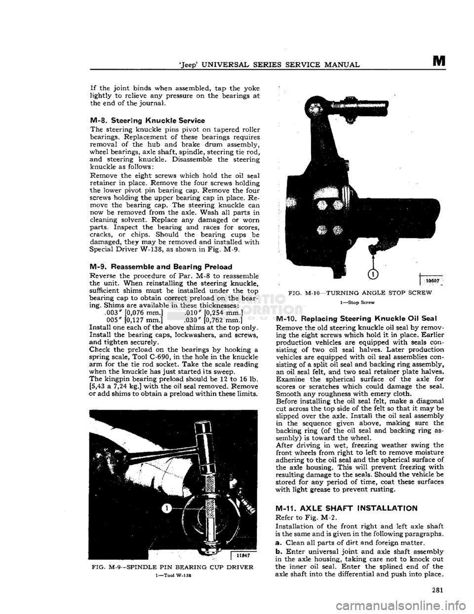
Special
Driver
W-138, as shown in Fig. M-9.
M-9.
Reassemble
and
Bearing Preload
Reverse
the procedure of Par. M-8 to reassemble
the unit. When reinstalling the steering knuckle, sufficient shims must be installed under the top
bearing
cap to obtain correct preload on the bear
ing.
Shims are available in
these
thicknesses: .003"
[0,076
mm.] .010"
[0,254
mm.] 005"
[0,127
mm.] .030"
[0,762
mm.]
Install
one each of the
above
shims at the top only.
Install
the bearing caps, lockwashers, and screws,
and
tighten securely.
Check
the preload on the bearings by hooking a
spring
scale, Tool C-690, in the
hole
in the knuckle
arm
for the tie rod socket.
Take
the scale reading when the knuckle has just started its
sweep.
The
kingpin bearing preload should be 12 to 16 lb. [5,43 a 7,24 kg.] with the oil seal removed. Remove
or
add shims to obtain a preload within
these
limits.
FIG.
M-9—SPINDLE
PIN
BEARING
CUP
DRIVER
1—Tool
W-138
FIG.
M-10—TURNING
ANGLE
STOP
SCREW
1—Stop
Screw
M-10.
Replacing Steering
Knuckle
Oil Seal
Remove the old steering knuckle oil seal by remov ing the
eight
screws which hold it in place.
Earlier
production vehicles are equipped with seals con sisting of two oil seal halves.
Later
production vehicles are equipped with oil seal assemblies con
sisting of a split oil seal and backing ring assembly,
an
oil seal felt, and two seal retainer plate halves.
Examine
the spherical surface of the axle for scores or scratches which could damage the seal.
Smooth any roughness with emery cloth. Before installing the oil seal felt, make a diagonal
cut across the top side of the
felt
so that it may be
slipped over the axle.
Install
the oil seal assembly
in
the
sequence
given above, making sure the
backing
ring (of the oil seal and backing ring as
sembly) is toward the wheel.
After
driving in wet, freezing weather swing the
front
wheels
from right to
left
to remove moisture
adhering
to the oil seal and the spherical surface of
the axle housing.
This
will
prevent freezing with
resulting
damage to the seals. Should the vehicle be
stored for any period of time, coat
these
surfaces
with
light grease to prevent rusting.
M-11.
AXLE
SHAFT
INSTALLATION
Refer
to Fig. M-2.
Installation
of the front right and
left
axle shaft
is the same and is given in the following
paragraphs.
a.
Clean
all parts of
dirt
and foreign matter.
b.
Enter
universal joint and axle shaft assembly
in
the axle housing, taking care not to knock out
the inner oil seal.
Enter
the splined end of the
axle shaft
into
the differential and push
into
place. 281
Page 282 of 376
FRONT
AXLE
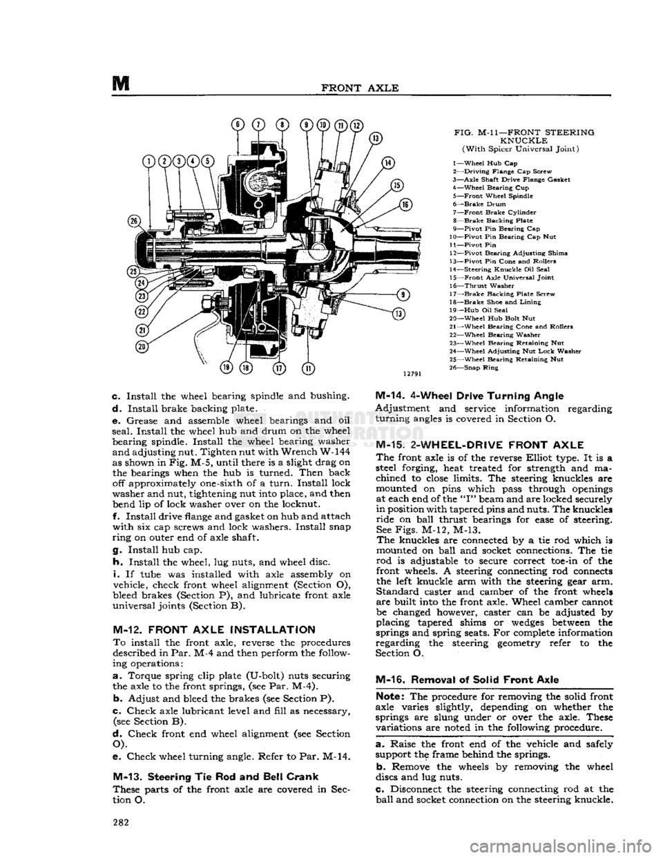
FIG.
M-l
1—FRONT
STEERING
KNUCKLE
(With
Spicer Universal Joint)
1—
Wheel
Hub Cap
2—
Driving
Flange Cap Screw
3—
Axle
Shaft Drive Flange Gasket 4—
Wheel
Bearing Cup
5—
Front
Wheel Spindle
6—
Brake
Drum
7—
Front
Brake
Cylinder
8—
Brake
Backing Plate
9—
Pivot
Pin Bearing Cap
10—
Pivot
Pin Bearing Cap Nut
11—
Pivot
Pin 12—
Pivot
Bearing Adjusting Shims
13—
Pivot
Pin Cone and Rollers
14—
Steering
Knuckle
Oil Seal 15—
Front
Axle Universal Joint
16—
Thrust
Washer
17—
Brake
Backing Plate Screw
18—
Brake
Shoe and
Lining
19—
Hub
Oil Seal
20—
Wheel
Hub Bolt Nut
21—
Wheel
Bearing Cone and Rollers 22—
Wheel
Bearing Washer
23—
Wheel
Bearing Retaining Nut
24—
Wheel
Adjusting Nut
Lock
Washer
25—
Wheel
Bearing Retaining Nut
26—
Snap
Ring
c.
Install
the wheel bearing spindle and bushing.
d.
Install
brake backing plate.
e.
Grease and assemble wheel bearings and oil
seal.
Install
the wheel hub and drum on the wheel
bearing
spindle.
Install
the wheel bearing washer
and
adjusting nut. Tighten nut with
Wrench
W-144
as shown in
Fig.
M-5, until there is a slight drag on the bearings when the hub is turned.
Then
back off approximately one-sixth of a
turn.
Install
lock
washer
and nut, tightening nut
into
place, and then bend lip of lock washer over on the locknut.
f.
Install
drive
flange
and gasket on hub and attach
with
six cap screws and lock washers.
Install
snap
ring
on outer end of axle shaft.
g.
Install
hub cap.
h.
Install
the wheel, lug nuts, and wheel disc.
i.
If
tube
was installed with axle assembly on
vehicle, check front wheel alignment (Section O),
bleed brakes (Section P), and lubricate front axle
universal
joints (Section B).
M-12.
FRONT
AXLE
INSTALLATION
To
install the front axle, reverse the procedures described in
Par.
M-4 and then perform the follow
ing operations:
a.
Torque spring clip plate (U-bolt) nuts securing the axle to the front springs, (see Par. M-4).
b.
Adjust and bleed the brakes (see Section P).
c.
Check
axle lubricant level and
fill
as necessary, (see Section B).
d.
Check
front end wheel alignment (see Section
O).
e.
Check
wheel turning angle. Refer to Par. M-14.
M-13.
Steering
Tie Rod and
Bell Crank
These
parts of the front axle are covered in Sec
tion O.
M-14.
4-Wheel Drive
Turning
Angle
Adjustment
and service information regarding
turning
angles
is covered in Section O.
M-15.
2-WHEEL-DRIVE
FRONT
AXLE
The
front axle is of the reverse
Elliot
type. It is a
steel forging, heat treated for strength and ma
chined
to
close
limits. The steering knuckles are
mounted on pins which pass through
openings
at each end of the
"I"
beam and are locked securely
in
position with tapered pins and nuts. The knuckles
ride
on
ball
thrust bearings for
ease
of steering. See
Figs.
M-12, M-13.
The
knuckles are connected by a tie rod which is
mounted on
ball
and socket connections. The tie
rod
is adjustable to secure correct
toe-in
of the front wheels. A steering connecting rod
connects
the
left
knuckle arm with the steering gear arm.
Standard
caster and camber of the front
wheels
are
built
into
the front axle. Wheel camber cannot
be changed however, caster can be adjusted by
placing
tapered shims or
wedges
between
the
springs and spring seats. For
complete
information
regarding
the steering
geometry
refer to the
Section O.
M-16.
Removal of Solid
Front
Axle
Note:
The procedure for removing the solid front
axle varies slightly, depending on whether the
springs are slung under or over the axle. These
variations
are
noted
in the following procedure.
a. -
Raise the front end of the vehicle and safely support the frame behind the springs.
b.
Remove the
wheels
by removing the wheel
discs and lug nuts.
c.
Disconnect the steering connecting rod at the
ball
and socket connection on the steering knuckle. 282
Page 283 of 376
'Jeep'
UNIVERSAL
SERIES SERVICE
MANUAL
M
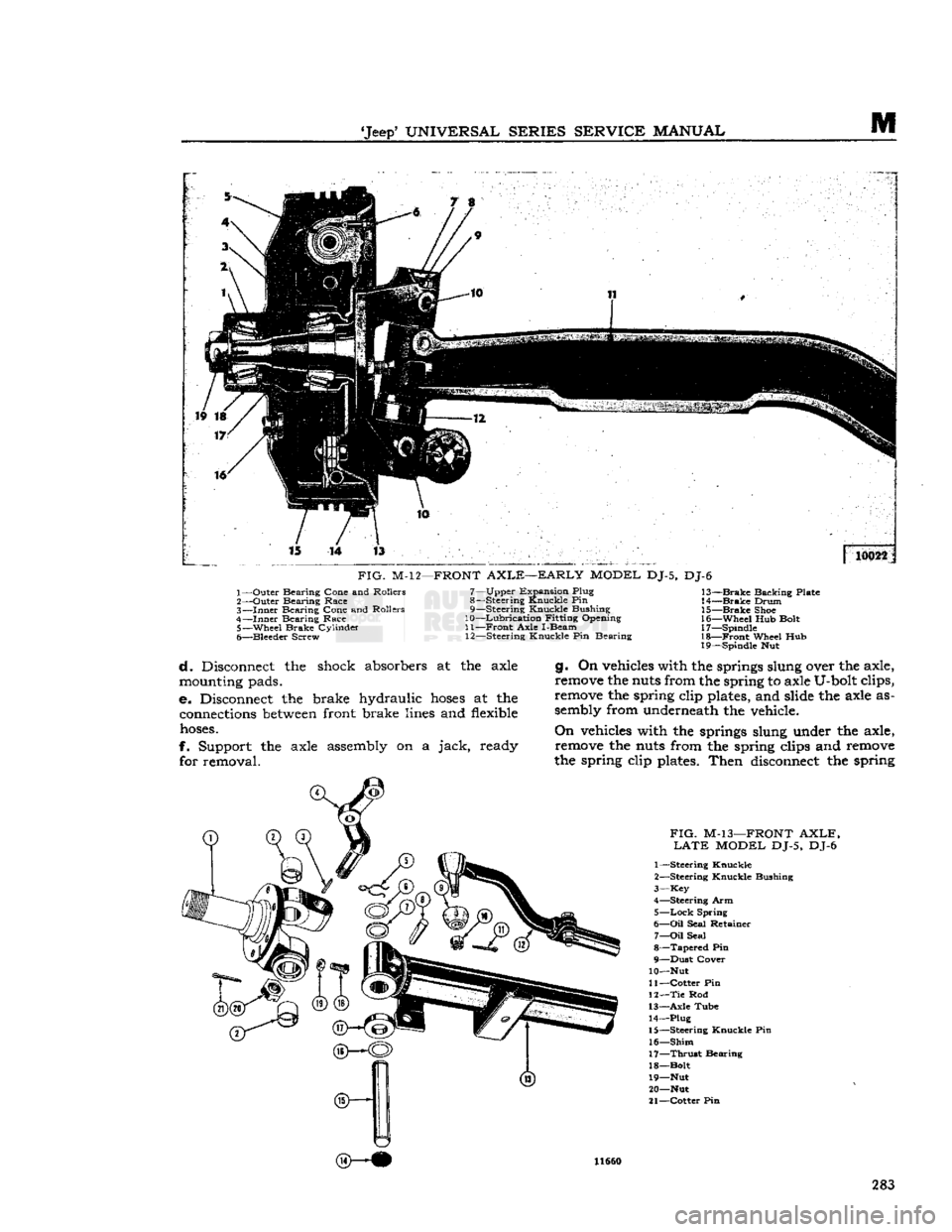
FIG.
M-12—FRONT
AXLE—EARLY
MODEL
DJ-5, DJ-6
1— Outer Bearing Cone and Rollers
2— Outer Bearing Race
3—
Inner
Bearing Cone and Rollers
4—
Inner
Bearing Race 5— -Wheel Brake Cylinder
6— Bleeder Screw 7— Upper Expansion Plug
8— Steering Knuckle Pin
9— Steering Knuckle Bushing
10—
Lubrication
Fitting Opening
11—
Front
Axle I-Beam 12— Steering Knuckle Pin Bearing 13—
Brake
Backing Plate
14—
Brake
Drum 15—
Brake
Shoe
16— Wheel Hub Bolt
17— Spindle
18—
Front
Wheel Hub
19— Spindle Nut
d. Disconnect the shock absorbers at the axle
mounting
pads.
e. Disconnect the brake hydraulic
hoses
at the
connections
between
front brake
lines
and
flexible
hoses.
f. Support the axle assembly on a jack, ready for removal. g. On
vehicles
with the springs slung over the axle,
remove
the
nuts
from the spring to axle U-bolt clips,
remove
the spring clip
plates,
and slide the axle as
sembly
from underneath the vehicle.
On
vehicles
with the springs slung under the axle,
remove
the
nuts
from the spring clips and
remove
the spring clip
plates.
Then
disconnect
the spring
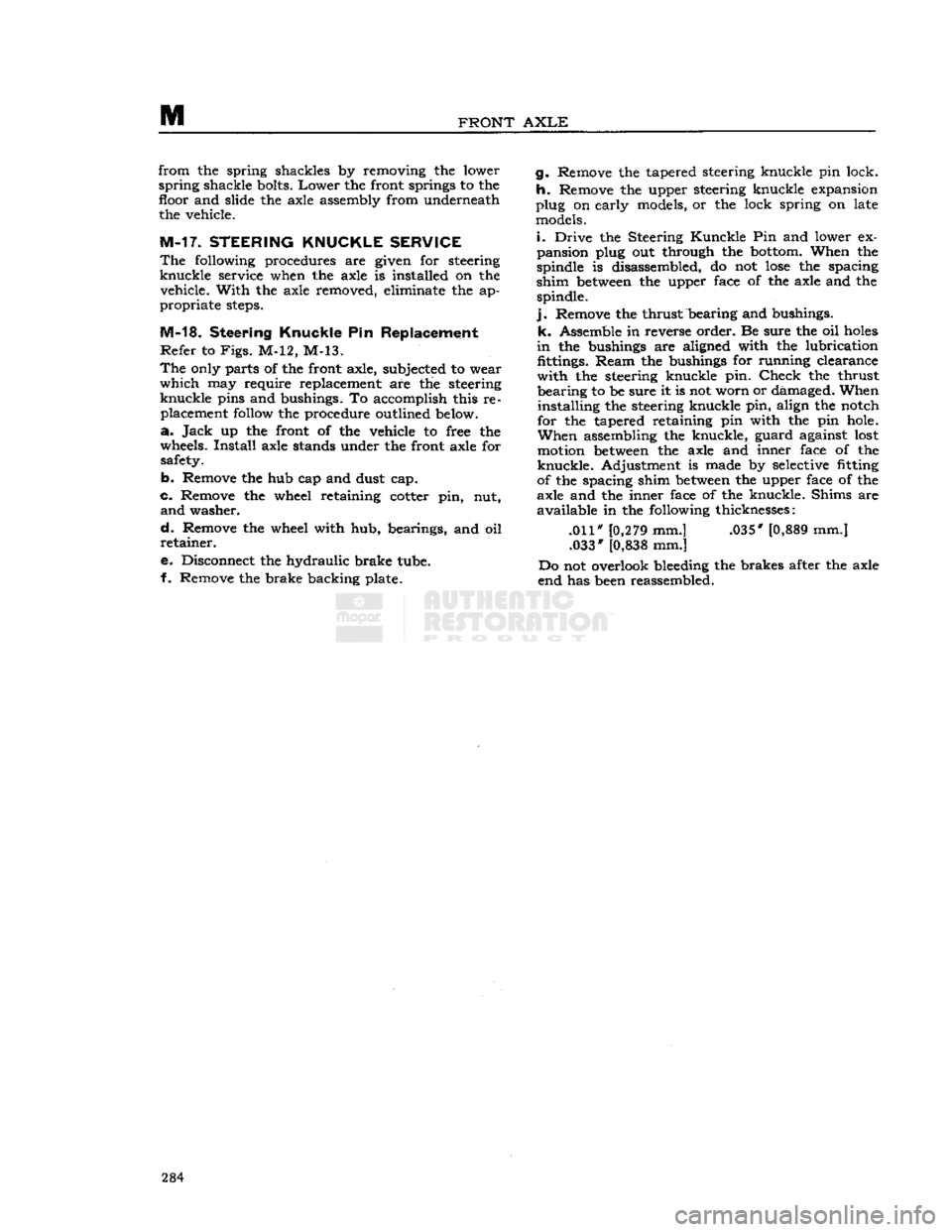
FIG.
M-13—FRONT
AXLE, LATE
MODEL
DJ-5, DJ-6
1— Steering Knuckle
2— Steering Knuckle Bushing
3—
Key
4— Steering Arm
5—
Lock
Spring
6—
Oil
Seal Retainer 7—
Oil
Seal
8—
Tapered
Pin
9— Dust Cover
10— Nut
11— Cotter Pin
12— Tie
Rod
13— Axle Tube 14— Plug
15— Steering Knuckle Pin
16—
Shim
17—
Thrust
Bearing
18— Bolt
19— Nut 20— Nut
21— Cotter Pin 11660
283
Page 284 of 376
M
FRONT
AXLE
from
the spring shackles by removing the lower
spring
shackle bolts.
Lower
the front springs to the floor and slide the axle assembly from underneath the vehicle.
M-17. STEERING KNUCKLE SERVICE
The
following procedures are given for steering
knuckle
service when the axle is installed on the vehicle.
With
the axle removed, eliminate the ap
propriate
steps.
M-18.
Steering
Knuckle
Pin Replacement
Refer
to
Figs.
M-12, M-13.
The
only parts of the front axle, subjected to weir
which
may require replacement are the steering
knuckle
pins and bushings. To accomplish this re placement follow the procedure outlined below.
a.
Jack
up the front of the vehicle to free the
wheels.
Install
axle stands under the front axle for safety.
b.
Remove the hub cap and dust cap.
c.
Remove the wheel retaining cotter pin, nut,
and
washer.
d.
Remove the wheel with hub, bearings, and oil
retainer.
e. Disconnect the hydraulic brake tube.
f. Remove the brake backing plate. g. Remove the tapered steering knuckle pin lock.
h.
Remove the upper steering knuckle expansion
plug on early models, or the lock spring on late models.
i.
Drive the Steering
Kunckle
Pin and lower ex
pansion plug out through the bottom. When the
spindle is disassembled, do not
lose
the spacing
shim
between
the upper face of the axle and the spindle.
j.
Remove the thrust bearing and bushings,
k.
Assemble in reverse order. Be sure the oil
holes
in
the bushings are aligned with the lubrication fittings.
Ream
the bushings for running clearance
with
the steering knuckle pin.
Check
the thrust
bearing
to be sure it is not worn or damaged. When
installing
the steering knuckle pin, align the notch
for the tapered retaining pin with the pin hole.
When
assembling the knuckle, guard against lost motion
between
the axle and inner face of the
knuckle.
Adjustment is made by selective fitting
of the spacing shim
between
the upper face of the
axle and the inner face of the knuckle. Shims are
available
in the following thicknesses:
.011" [0,279 mm.] .035* [0,889 mm.] .033* [0,838 mm.]
Do not overlook bleeding the brakes after the axle
end has been reassembled. 284
Page 285 of 376
'Jeep'
UNIVERSAL
SERIES
SERVICE
MANUAL
M
M-19.
SERVICE
DIAGNOSIS
SYMPTOMS
PROBABLE
REMEDY
Hard Steering
Lack
of
Lubrication
Lubricate
Tires
Soft.
. Inflate
Tight
Steering. Adjust. See "Steering" Section
Low Speed Shimmy
or
Wheel Fight
Spring
Clips and Shackles Loose
Front
Axle Shifted Insufficient Toe-In
Improper
Caster
Steering System Loose or Worn
Twisted Axle
High Speed Shimmy
or
Wheel Fight
Check
Conditions Under "Low Speed Shimmy"
Tire
Pressures Low or not
Equal
Wheel Out of Balance
Wheel Runout
Radial
Runout of Tires
Wheel Camber
Front
Springs
Settled
or Broken
Bent Steering Knuckle
Arm..................
Shock Absorbers not Effective
Steering
Gear
Loose on Frame
Front
Springs too Flexible
Tramp
Wheels Unbalanced
Wandering
Improper
Toe-in
Broken
Front Spring Main
Leaf
Axle Shifted Loose Spring Shackles or Clips
Improper
Caster
Tire
Pressure Uneven
Tightness in Steering System
Loose Wheel Bearings
Front
Spring
Settled
or Broken
Axle
Noisy
on
Pull
Pinion and Ring
Gear
Adjusted too Tight
Pinion Bearings Rough.
Axle Noisy
on
Coast
Excessive Back
Lash
at Ring and Pinion Gears.
End
Play in Pinion Shaft. . . Rough Bearing.
Axle Noisy
on
Coast
and
Pull
Ring
and Pinion Adjusted too Tight
Pinion Set too
Deep
in Ring
Gear
Pinion Bearing Loose or Worn
Back Lash
Axle Shaft Universal Joint Worn
Axle Shaft Improperly Adjusted
Worn
Differential Pinion Washers
Worn
Propeller Shaft Universal Joints.
Readjust
or Replace
Broken
Spring Center Bolt
Adjust
Reset
Adjust
or Overhaul Steering
Gear,
Front Axle or
Steering Parts
Straighten or Adjust
Inflate
Balance
Straighten Mount Properly
Same on Both Wheels
Repair
or Replace
Straighten or Replace
Replace or Repair Tighten
Over
Lubricated
Check
and Balance
Adjust—Check
for Bent Steering Knuckle Arm Replace
Spring
Center Bolt Broken
Adjust
or Replace
Reset Inflate
Adjust
Adjust
Repair
or Replace
Readjust
Replace
Readjust
Readjust
Replace
Readjust Readjust
Readjust
or Replace
Replace
Readjust
Replace
Repair
Emergency
Where difficulty is experienced with front axle differential making the vehicle inoperative,
remove
axle driving
flanges.
This will allow bringing vehicle in under its own power. Be sure the transfer
case
shift lever is in the neutral
(disengaged)
position.
285
Page 313 of 376
'Jeep'
UNIVERSAL
SERIES SERVICE
MANUAL
STEERING SYSTEM
Contents
SUBJECT
PAR.
GENERAL......
O-l
Camber
Adjustment 0-9
Caster
Adjustment. .0-10
Front
Wheel Alignment Adjustments.....
.
0-6
Front
Wheel Shimmy 0-13
Front
Wheel Turning Angle Oil
Steering Knuckle Arm O-l2
Steering
Gear
Function 0-2
Steering Linkage 0-3
Toe-in
Adjustment 0-7, 8
STEERING LINKAGE SERVICE..
O-l4
Drag
Link
or Connecting Rod O-l5
Tie
Rod 0-16
Tie
Rod Removal.. O-l7
Beilcrank
Service O-l8
SUBJECT
PAR.
STEERING GEAR SERVICE
.0-22 Reassembly of Steering
Gear
0-25 Disassembly of Steering
Gear
0-24 Installation of Steering
Gear
0-26
Removal
of Steering
Gear
0-23
Steering
Gear
Adjustment. . 0-5
STEERING
COLUMN
AND
WHEEL SERVICE.
..................
.0-20
Steering Column Adjustments 0-4
Steering Wheel Installation 0-27
Steering Wheel Removal 0-21
SERVICE
DIAGNOSIS.
. 0-28
SPECIFICATIONS.
.0-29
<§>-
i©1
CJ-3B
0
0 0
®
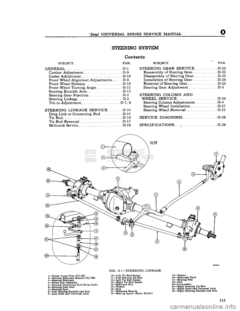
1—
Frame
Cross Tube
(CJ-3B)
2— Steering Beilcrank Bracket
(CJ-3B)
3—
Steering Beilcrank
4—
Front
Axle Assembly 5— Steering Connecting Rod (Drag
Link)
6— Steering
Gear
Arm
7—
Steering
Gear
8—
Left
Steering Knuckle and Arm
9—
Left
Shaft and Universal Joint
FIG.
O-l—STEERING LINKAGE
10—
Left
Tie Rod Socket 11—
Left
Steering Tie Rod
12—
Left
Tie Rod Socket 13—
Right
Tie Rod Socket
14—
Beilcrank
Nut
15—
Washer
16— Bolt 17—
Beilcrank
Bearing 18—
Bearing
Spacer
(Early
Model) 19—
Washer
20—
Beilcrank
Shaft
21—
Bearing
Seal
22— Nut
23—
Lockwasher
24—
Right
Steering Tie Rod 25—
Right
Shaft and Universal Joint 26—
Right
Steering Knuckle and Arm 313
Page 314 of 376
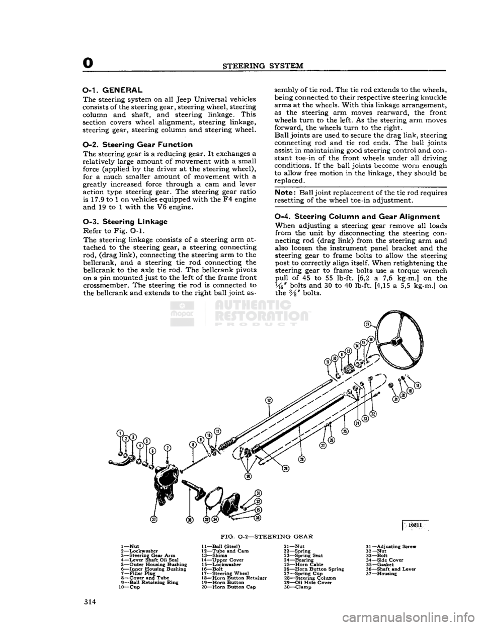
STEERING
SYSTEM
O-L
GENERAL
The
steering system on all Jeep Universal vehicles
consists of the steering gear, steering wheel, steering column and shaft, and steering linkage.
This
section covers wheel alignment, steering linkage,
steering gear, steering column and steering wheel.
0-2. Steering
Gear
Function
The
steering gear is a reducing gear. It exchanges a
relatively
large amount of movement with a small force (applied by the driver at the steering wheel), for a much smaller amount of movement with a
greatly increased force through a cam and lever
action type steering gear. The steering gear ratio is 17.9 to 1 on vehicles equipped with the F4
engine
and
19 to 1 with the V6 engine.
0-3. Steering
Linkage
Refer
to Fig. O-l.
The
steering linkage consists of a steering arm at
tached to the steering gear, a steering connecting
rod,
(drag
link),
connecting the steering arm to the
beilcrank,
and a steering tie rod connecting the
beilcrank
to the axle tie rod. The beilcrank pivots
on a pin mounted just to the left of the frame front crossmember. The steering tie rod is connected to
the beilcrank and
extends
to the right
ball
joint as sembly of tie rod. The tie rod
extends
to the wheels,
being connected to their respective steering knuckle
arms
at the wheels.
With
this linkage arrangement,
as the steering arm
moves
rearward,
the front
wheels
turn
to the left. As the steering arm
moves
forward,
the wheels
turn
to the right.
Ball
joints are used to secure the drag
link,
steering
connecting rod and tie rod ends. The
ball
joints
assist in maintaining
good
steering control and con
stant toe-in of the front wheels under all driving conditions. If the
ball
joints
become
worn enough
to allow free motion in the linkage, they should be,
replaced.
Note:
Ball
joint replacement of the tie rod requires
resetting of the wheel toe-in adjustment.
0-4.
Steering
Column
and Gear
Alignment
When
adjusting a steering gear remove all loads
from
the unit by disconnecting the steering con
necting rod (drag
link)
from the steering arm and
also
loosen
the instrument panel bracket and the
steering gear to frame
bolts
to allow the steering
post
to correctly align itself. When retightening the
steering gear to frame
bolts
use a torque wrench
pull
of 45 to 55 lb-ft. [6,2 a 7,6 kg-m.] on the
Vk*
bolts
and 30 to 40 lb-ft. [4,15 a 5,5 kg-m.] on the
Vs"
bolts. 10811
FIG.
0-2—STEERING
GEAR
1—Nut
2
—Lockwasher
3—
Steering
Gear
Arm 4—
Lever
Shaft Oil Seal
5—
Outer
Housing Bushing
6—
Inner
Housing Bushing 7—
Filler
Plug
8—
Cover
and Tube
9—
Ball
Retaining
Ring
10—Cup
11—
Ball
(Steel)
12—
Tube
and Cam
13—
Shims
14—
Upper
Cover
15—
Lockwasher
16—
Bolt
17—
Steering
Wheel 18—
Horn
Button Retainer
19—
Horn
Button
20—
Horn
Button Cap 21— Nut
22—
Spring
23—
Spring
Seat
24—
Bearing
25—
Horn
Cable
26—
Horn
Button Spring
27—
Spring
Cup
28—
Steering Column
29—
Oil
Hole
Cover
30—
Clamp
31—
Adjusting
Screw
32— Nut
33—
Bolt
34—
Side
Cover
35—
Gasket
36—
Shaft
and
Lever
37—
Housing
314
Page 315 of 376
'Jeep'
UNIVERSAL
SERIES SERVICE
MANUAL
O Note:
If the steering-gear-to-frame
bolts
are not
properly
torqued, they
will
eventually
loosen
dur
ing operation of the vehicle. Loose
bolts
will
result
in
elongated
bolt
holes
making maintenance of bolt torque difficult, and may allow position of the
steering columns to be misaligned. Therefore,
proper
torquing is extremely important.
Do not tighten the steering gear to dampen out
steering trouble. Adjust the steering gear only to
remove lost motion or play within the unit.
0-5. Steering
Gear
Adjustment
The
cam and lever steering gear is illustrated in
Fig.
0-2. It consists of a
spiral
cam, and a cross shaft and lever assembly with two lever studs.
When
the steering wheel is turned, the cam
moves
the studs, causing rotary movement of the cross
shaft, which in
turn
causes angular movement of
the*steering arm.
Two
adjustments of the steering gear are necessary:
up and down play of the steering shaft, and adjustment of the lever studs (tapered pins) in the
cam
groove.
Adjustment
of the
ball
thrust bearings to eliminate up and down play of the steering shaft is ac
complished by removing shims which are installed
between
the steering gear housing and the upper
cover. Before making this adjustment
loosen
the
housing side cover adjusting screw to free the pins
in
the cam groove. Loosen the housing cover to
cut and remove a shim or more as required.
Install
the screws and tighten. Adjustment should be
made to have a slight drag but allow the steering
wheel to
turn
freely with thumb and forefinger
lightly gripping the rim.
Shims
installed for adjustment are .002*, .003", and .010"
[.0508,
.0762
and .254 mm.] in thickness.
Adjustment
of the tapered pins in the cam
groove
is accomplished by adjusting screw. Unlock the
adjusting
screw and
turn
it in until a very slight
drag
is felt through the mid-position when turning
the steering wheel slowly from one extreme position
to the other.
Backlash
of the pins in the
groove
shows up as
end play of lever shaft, also as backlash of steer ing arm.
The
cam
groove
is purposely cut shallow in the
straight
ahead driving position for each pin.
This
feature permits a
close
adjustment for normal
straight
ahead driving and provides precision steer ing and permits take up of backlash at this point
after the wear occurs without causing a bind else
where.
Always
adjust within the high range through
the mid-position of pin travel. Do not adjust off
"straight
ahead" position.
Backlash
in turned posi
tions is not objectionable.
0-6.
Front
Wheel Alignment Adjustments
To
ensure correct alignment, a definite procedure
for inspection of the steering system is recom mended. It is
suggested
that the following sequence
be used:
a.
Equalize
tire pressures and level vehicle.
b.
Check
steering gear to steering column align
ment.
c.
Inspect steering knuckle pivots, spindle, and
wheel bearing
looseness.
d.
Check
wheel runout.
e.
Test wheel balance and bearing adjustment.
f.
Check
for spring sag.
g.
Inspect brakes and shock absorbers.
h.
Check
steering gear assembly adjustment and
steering connecting rod.
i.
Check
caster,
j.
Check
toe-in.
k.
Check
toe-out
on turns.
I.
Check
camber.
m.
Check
tracking of front and
rear
wheels,
n.
Check
frame alignment.
The
factors of alignment, caster, camber, and toe-
in,
are all interrelated and if one adjustment is
made, another adjustment may be affected.
There
fore, after an alignment job is completed, make a
complete recheck of all the adjustments to be sure
the
settings
are within the limit. Be sure all front
suspension and steering system nuts and
bolts
are
all
properly torqued before taking wheel alignment readings.
Proper
alignment of front wheels must be main
tained in order to ensure
ease
of steering and satisfactory tire life.
The
most important factors of front wheel alignment are wheel camber, axle caster and wheel
toe-in.
Wheel
toe-in is the distance the wheels are closer
together
at the front than at the
rear.
Wheel
camber is the amount the wheels incline out
ward
at the top from a vertical position.
Front
axle caster is the amount in
degrees
that the
steering pivot pins are tilted towards the front or
rear
of the vehicle. Positive caster is inclination of
the top of the pivot pin towards the
rear
of the ve
hicle.
Zero caster is the vertical position of the
pivot pin. Negative or reverse caster is the in
clination
of the top of the pin towards the front
of the vehicle.
These
points should be checked at regular inter
vals,
particularly when the front axle has been
subjected to a heavy impact. When checking wheel alignment, it is important that wheel bearings and
knuckle
bearings be in proper adjustment. Loose bearings
will
affect instrument readings when
checking
the camber, pivot pin inclination and
toe-in.
To
accurately check camber and caster, use a wheel
aligning fixture.
Camber
and caster of the front
wheels are both preset.
Camber
cannot be altered
but caster can be adjusted by installing caster shims
between
the axle pad and the springs. Wheel toe-in
may
be adjusted. To measure wheel toe-in, use a
wheel aligning fixture or follow the procedure given
in Par.
0-8.
0-7.
Front Wheel Toe-in
Toe-in
as illustrated in
Fig.
0-3, is necessary to
off
set the
effect
of camber as shown in Fig. Q-4. 315