service JEEP CJ 1953 Workshop Manual
[x] Cancel search | Manufacturer: JEEP, Model Year: 1953, Model line: CJ, Model: JEEP CJ 1953Pages: 376, PDF Size: 19.96 MB
Page 71 of 376
'Jeep*
UNIVERSAL
SERIES
SERVICE
MANUAL
D D-l 13. HURRICANE
F4
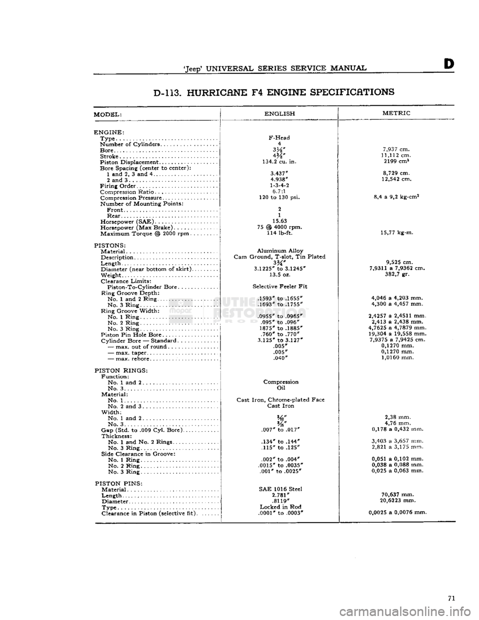
ENGINE SPECIFICATIONS
MODEL:
ENGLISH
ENGINE:
Type
Number of Cylinders
Bore
Stroke
Piston Displacement...........
Bore
Spacing (center to center): 1 and 2, 3 and 4
2 and 3
Firing
Order Compression Ratio Compression Pressure... .
Number of Mounting Points:
Front
Rear
Horsepower (SAE)
Horsepower (Max Brake) Maximum Torque @
2000
rpm.
PISTONS:
Material
Description
Length
,.
Diameter (near
bottom
of
skirt).
Weight.
Clearance
Limits:
Piston-To-Cylindcr
Bore
Ring
Groove Depth:
No. 1 and 2 Ring No. 3 Ring
Ring
Groove Width:
No. 1 Ring No. 2 Ring
No. 3 Ring
Piston Pin Hole Bore
Cylinder
Bore — Standard.....
—
max. out of round
F-Head
4
W
134.2 cu. in.
3.437"
4.938"
1-3-4-2
6.7:1
120 to 130 psi.
2
1
15.63
@
4000
rpm. 114 lb-ft. 75
-
max. taper..
-
max. rebore.
PISTON RINGS:
Function:
No. 1 and 2 No. 3. .
Material:
No. 1. .
No. 2 and 3
Width;
No. 1 and 2
No. 3. . . .
Gap
(Std. to .009 Cyl. Bore).
Thickness:
No. 1 and No. 2 Rings....
No. 3 Ring
Side Clearance in Groove:
No. 1 Ring No. 2 Ring
No. 3 Ring
PISTON
PINS:
Material
Length
Diameter
Type
Clearance
in Piston
(selective
fit).
Aluminum
Alloy
Gam
Ground, T-slot, Tin Plated
3.1225*
to
3.1245*
13.5 oz.
Selective Feeler Fit
.1593" to .1655"
.1693" to .1755"
.0955" to .0965" .095" to .096"
1875" to .1885" .760" to .770"
3.125"
to
3.127"
.005" .005" .040"
Compression
Oil
Cast
Iron,
Chrome-plated Face
Cast
Iron
.007" to .017"
.134" to .144" .115" to .125"
.002" to .004"
.0015" to .0035" .001" to .0025"
SAE
1016 Steel
2.781"
.8119"
Locked
in Rod
.0001"
to .0003"
METRIC
7,937
cm.
11,112
cm. 2199 cm*
8,729
cm.
12,542
cm.
8,4 a 9,2 kg-cm2
15,77 kg-m.
9,525
cm.
7,9311
a
7,9362
cm.
382,7
gr.
4,046
a
4,203
mm.
4,300
a
4,457
mm.
2,4257
a
2,4511
mm. 2,413 a
2,438
mm.
4,7625
a
4,7879
mm.
19,304
a
19,558
mm.
7,9375
a
7,9425
cm.
0,1270
mm.
0,1270
mm.
1,0160
mm.
2,38 mm.
4,76 mm.
0,178 a
0,432
mm.
3,403
a
3,657
mm. 2,821 a 3,175 mm.
0,051 a 0,102 mm.
0,038
a
0,088
mm.
0,025
a
0,063
mm.
70,637
mm.
20,6223
mm.
0,0025
a
0,0076
mm. 71
Page 73 of 376
'Jeep'
UNIVERSAL SERIES SERVICE
MANUAL
D
D-l 13. HURRICANE
F4
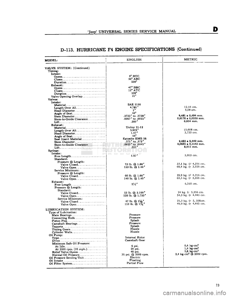
ENGINE SPECIFICATIONS
(Continued)
MODEL:
VALVE
SYSTEM:
(Continued) Timing: Intake:
Opens Closes
Duration
Exhaust: Opens
Closes Duration
Valve Opening Overlap
Valves: Intake: Material
Length Over All. Head Diameter.
.........
Angle
of Seat.
Stem
Diameter
Stem-to-Guide
Clearance..
Lift
Exhaust: Material
Length Over All Head Diameter
Angle
of
Seat Seat
Insert Material
Stem
Diameter
Stem-to-Guide
Clearance..
Lift
Springs: Intake:
Free
Length Standard: Pressure % Length: Valve Closed........
Valve Open
Service Minimum: Pressure @ Length: Valve Closed Valve Open
Exhaust:
Free
Length Pressure @ Length: Standard: Valve Closed
Valve Open
Service Minimum: Valve Closed. Valve Open
LUBRICATION SYSTEM:
Type of Lubrication:
Main
Bearings Connecting Rods
Piston Pins Camshaft Bearings
Tappets
Timing Gears.'.
Cylinder
Walls
Oil
Pump: Type Drive
Minimum
Safe
Oil Pressure:
At
Idle
At
2000
rpm. (35 mph.)..
Relief Valve Opens Normal Oil Pressure
Oil
Pressure
Sending
Unit
Oil
Intake
Oil
Filter
System
ENGLISH
9°
BTC
50°
ABC
239°
47°
BBC 12* ATC
239°
21°
SAE
5150
4.781"
2*
46°
.3733"
to
.3738"
.0007"
to
.0022'
.260"
Uniloy 21-12
5.909"
1.47"
46°
Eatonite EMS 58 .371" to .372"
.0025"
to
.0045'
.351"
1.97"
73 lb. @ 1.66"
153 lb. @ 1.40* 66 lb.
140 lb. 1.66*
)
1.40" 53 lb. (
120 lb.
2.109"
\
1.750*
47 lb. @2W
110 lb. @ l%*
Pressure
Pressure Splash
Pressure
Splash
Nozzle
Nozzle
Internal
Rotor
Camshaft
Gear
6 psi.
20 psi.
40 psi.
35 psi. @
2000
rpm.
Electric
Floating
Partial
Flow
METRIC
12,14 cm. 5,08 cm.
9,481 a
9,494
mm.
0,0178
a
0,0559
mm.
6,604
mm.
15,008
cm.
3,733
cm.
9,423
a
9,449
mm.
0,0635
a
0,1143
mm. 8,915 mm.
5,003
cm.
33,1 kg.
(i(<
4,216 cm.
69,4 kg. (a.
3,556
cm.
29,9 kg. (d 4,216 cm.
63,5 kg. ((i
3,556
cm.
6,350
cm.
24 kg. (a
5,356
cm.
54,3 kg. (a
4,445
cm.
21,3 kg. (n 5,
356cm.
49,9 kg. («
4,445
cm.
0,4 kg-cm2 1,4 kg-cm2
2,8 kg-cm2
2,4 kg-cm2 @
2000
rpm. 73
Page 75 of 376
'Jeep'
UNIVERSAL SERIES
SERVICE
MANUAL
Dl
DAUNTLESS
V-6
ENGINE
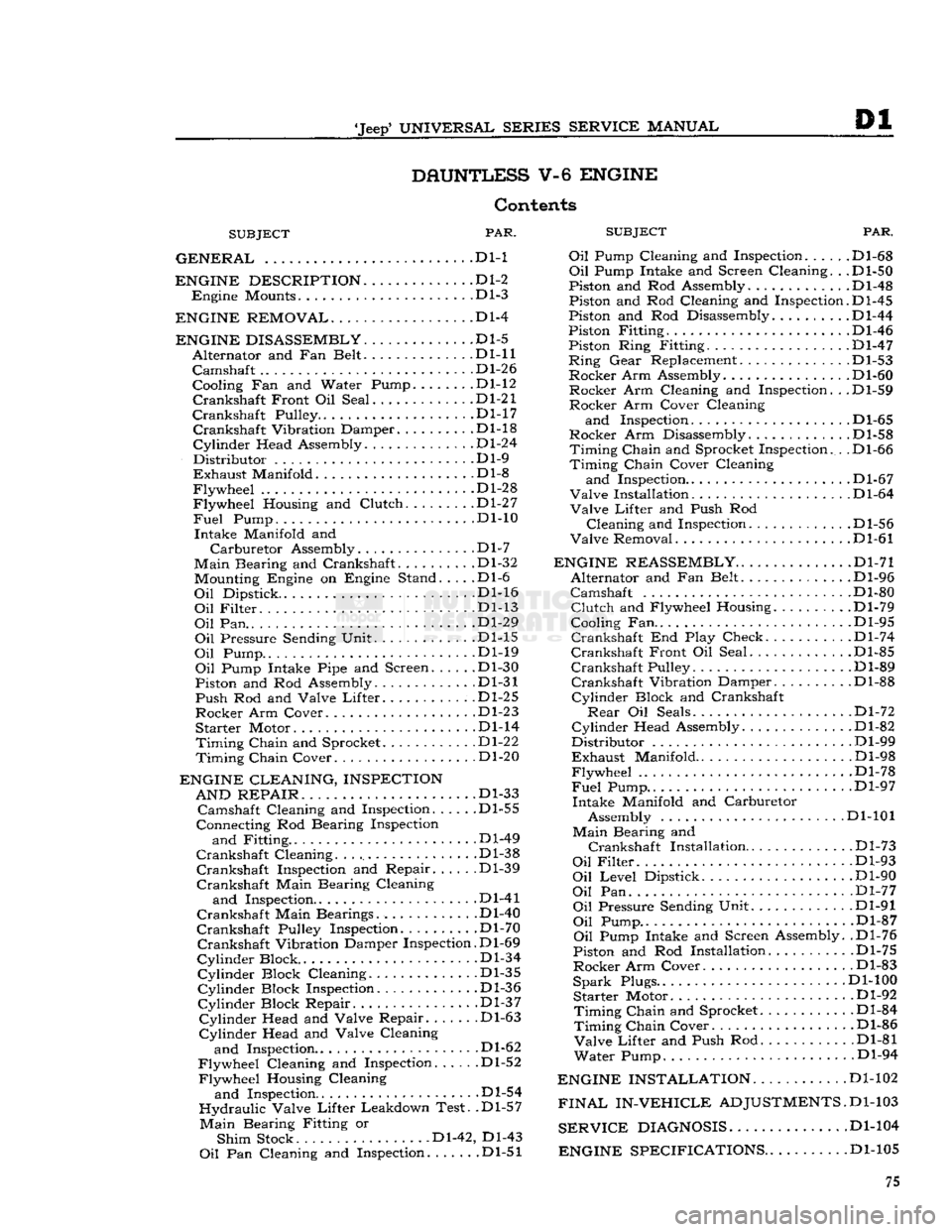
Contents
SUBJECT
PAR.
SUBJEC
GENERAL
.... . . Dl-1 Oil Pump Cl(
ENGINE DESCRIPTION
D1-2
Engine
Mounts Dl-3
ENGINE REMOVAL
Dl-4
ENGINE DISASSEMBLY
Dl-5
Alternator
and Fan Belt Dl-11
Camshaft
.... Dl-26
Cooling Fan and Water Pump.
......
.Dl-12
Crankshaft
Front Oil Seal .Dl-21
Crankshaft
Pulley D1-17
Crankshaft
Vibration Damper Dl-18
Cylinder
Head Assembly Dl-24
Distributor
Dl-9
Exhaust
Manifold .Dl-8
Flywheel
Dl-28
Flywheel
Housing and
Clutch
Dl-27
Fuel
Pump. ... . .Dl-10
Intake
Manifold and
Carburetor
Assembly.
.............
.Dl-7
Main
Bearing and Crankshaft. Dl-32 Mounting Engine on Engine Stand. . . . .Dl-6
Oil
Dipstick. Dl-16
Oil
Filter
Dl-13
Oil
Pan.. ...
.......
.Dl-29
Oil
Pressure Sending Unit Dl-15
Oil
Pump Dl-19
Oil
Pump Intake Pipe and Screen Dl-30
Piston and Rod Assembly. Dl-31
Push
Rod and Valve
Lifter.
.Dl-25
Rocker
Arm Cover Dl-23
Starter
Motor Dl-14
Timing
Chain
and Sprocket Dl-22
Timing
Chain
Cover Dl-20
ENGINE CLEANING, INSPECTION AND REPAIR
. . ... .Dl-33
Camshaft
Cleaning and Inspection Dl-55
Connecting Rod Bearing Inspection
and
Fitting .Dl-49
Crankshaft
Cleaning Dl-38
Crankshaft
Inspection and Repair Dl-39
Crankshaft
Main Bearing Cleaning
and
Inspection Dl-41
Crankshaft
Main Bearings. Dl-40
Crankshaft
Pulley Inspection. Dl-70
Crankshaft
Vibration Damper Inspection. D1-69
Cylinder
Block .Dl-34
Cylinder
Block Cleaning Dl-35
Cylinder
Block Inspection Dl-36
Cylinder
Block Repair. .Dl-37
Cylinder
Head and Valve Repair .Dl-63
Cylinder
Head and Valve Cleaning
and
Inspection.. . .Dl-62
Flywheel
Cleaning and Inspection Dl-52
Flywheel
Housing Cleaning
and
Inspection Dl-54
Hydraulic
Valve
Lifter
Leakdown Test. .Dl-57
Main
Bearing Fitting or
Shim
Stock Dl-42, Dl-43
Oil
Pan Cleaning and Inspection .Dl-51
PAR.
and
Inspection. .... .Dl-68
Oil
Pump Intake and Screen Cleaning. . .Dl-50
Piston and Rod Assembly.
...........
.Dl-48
Piston and Rod Cleaning and Inspection.D1-45
Piston and Rod Disassembly Dl-44
Piston Fitting Dl-46
Piston Ring Fitting. .Dl-47
Ring
Gear
Replacement. .Dl-53
Rocker
Arm Assembly. Dl-60
Rocker
Arm Cleaning and Inspection. . .Dl-59
Rocker
Arm Cover Cleaning
and
Inspection D1-65
Rocker
Arm Disassembly .Dl-58
Timing
Chain
and Sprocket Inspection. . .Dl-66
Timing
Chain
Cover Cleaning
and
Inspection.. . Dl-67
Valve
Installation D1-64
Valve
Lifter
and Push Rod
Cleaning
and Inspection. . Dl-56
Valve
Removal Dl-61
ENGINE REASSEMBLY
Dl-71
Alternator
and Fan Belt Dl-96
Camshaft
Dl-80
Clutch
and Flywheel Housing Dl-79
Cooling Fan.. . .Dl-95
Crankshaft
End Play Check. . Dl-74
Crankshaft
Front Oil Seal Dl-85
Crankshaft
Pulley Dl-89
Crankshaft
Vibration Damper Dl-88
Cylinder
Block and Crankshaft
Rear
Oil Seals Dl-72
Cylinder
Head Assembly .Dl-82
Distributor
Dl-99
Exhaust
Manifold Dl-98
Flywheel
.Dl-78
Fuel
Pump.. .. . Dl-97
Intake
Manifold and Carburetor Assembly Dl-101
Main
Bearing and
Crankshaft
Installation
.
Dl-73
Oil
Filter
Dl-93
Oil
Level
Dipstick Dl-90
Oil
Pan Dl-77
Oil
Pressure Sending Unit Dl-91
Oil
Pump.. .Dl-87
Oil
Pump Intake and Screen Assembly. .Dl-76
Piston and Rod Installation Dl-75
Rocker
Arm Cover. Dl-83
Spark
Plugs.. Dl-100
Starter
Motor Dl-92
Timing
Chain
and Sprocket.
..........
.Dl-84
Timing
Chain
Cover Dl-86
Valve
Lifter
and Push Rod Dl-81
Water
Pump. Dl-94
ENGINE INSTALLATION
Dl-102
FINAL
IN-VEHICLE
ADJUSTMENTS.
D1-103
SERVICE
DIAGNOSIS
Dl-104
ENGINE SPECIFICATIONS
. .Dl-105 75
Page 76 of 376
Dl
DAUNTLESS
V-6
ENGINE
DM.
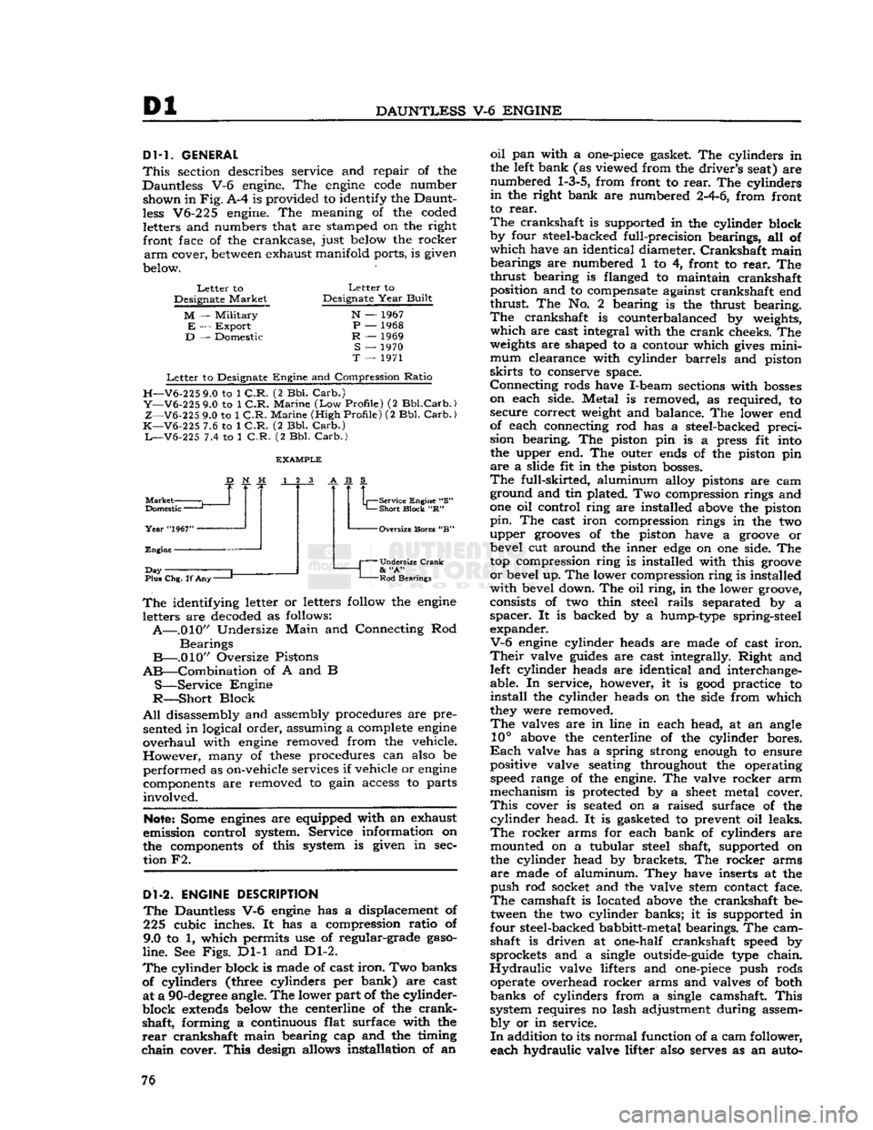
GENERAL
This
section describes service and repair of the
Dauntless V-6 engine. The
engine
code
number shown in
Fig.
A-4 is provided to identify the Daunt
less
V6-225 engine. The meaning of the coded letters and numbers that are stamped on the right front face of the crankcase, just below the rocker
arm
cover,
between
exhaust manifold ports, is given
below.
Letter
to
Designate
Market
M
—
Military
E
—
Export
D
— Domestic
Letter
to
Designate
Year
Built
N
— 1967
P
— 1968
R
— 1969
S
— 1970
T
— 1971
Letter
to Designate
Engine
and Compression
Ratio
H—V6-225
9.0 to 1
C.R.
(2 Bbl.
Carb.)
Y—V6-225
9.0 to 1
C.R.
Marine
(Low
Profile)
(2
Bbl.Carb.)
Z—V6-225
9.0 to 1
C.R.
Marine
(High
Profile)
(2 Bbl.
Carb.)
K—V6-225
7.6 to 1
C.R.
(2 Bbl.
Carb.)
L—V6-225
7.4 to 1
C.R.
(2 Bbl.
Carb.)
Market
Domestic
—
Year
"1967"
Engine
J
Day
Plus Chg. If
Any-
Service Engine "S"
Short
Block
"R" -Oversize Bores "B"
Undersize Crank
&
"A"
Rod
Bearings
The
identifying letter or letters follow the
engine
letters are decoded as follows:
A—.010"
Undersize
Main
and Connecting Rod
Bearings
B—.010"
Oversize Pistons
AB—Combination
of A and B
S—Service
Engine
R—Short
Block
All
disassembly and assembly procedures are pre sented in logical order, assuming a complete
engine
overhaul
with
engine
removed from the vehicle.
However,
many of
these
procedures can also be
performed as on-vehicle services if vehicle or
engine
components are removed to gain access to parts
involved.
Note:
Some
engines
are equipped with an exhaust
emission control system. Service information on
the components of this system is given in sec tion F2.
Dl-2.
ENGINE
DESCRIPTION
The
Dauntless V-6
engine
has a displacement of
225 cubic inches. It has a compression ratio of
9.0 to 1, which permits use of regular-grade
gaso
line.
See
Figs.
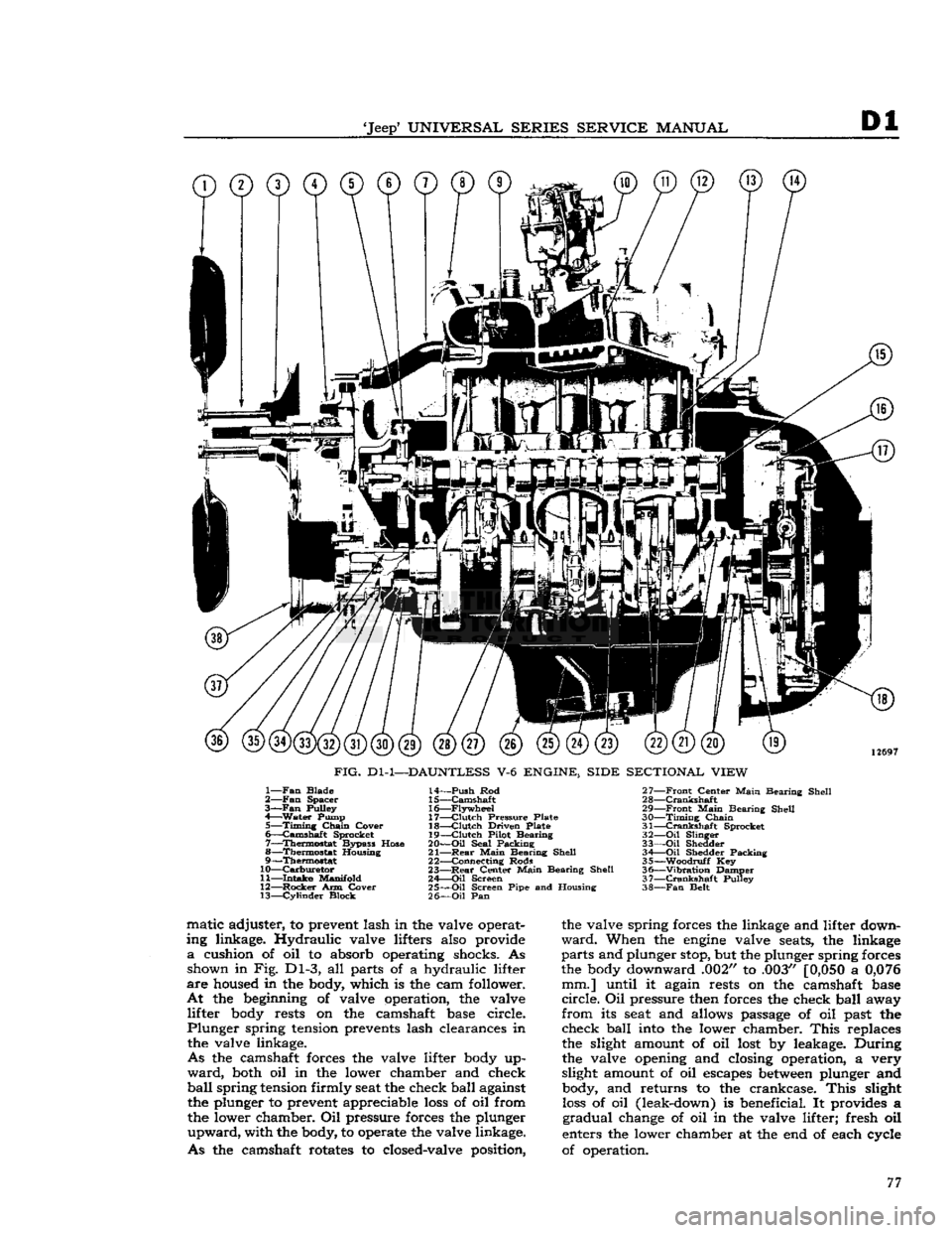
Dl-1 and Dl-2.
The
cylinder block is made of cast
iron.
Two banks
of cylinders (three cylinders per bank) are cast at a
90-degree
angle. The lower part of the cylinder-
block
extends
below the centerline of the
crank
shaft, forming a continuous flat surface with the
rear
crankshaft main bearing cap and the timing
chain
cover.
This
design allows installation of an
oil
pan with a
one-piece
gasket. The cylinders in
the left bank (as viewed from the driver's seat) are
numbered
1-3-5,
from front to
rear.
The cylinders
in
the right bank are numbered
2-4-6,
from front
to
rear.
The
crankshaft is supported in the cylinder block
by four steel-backed full-precision bearings, all of
which
have an identical diameter.
Crankshaft
main bearings are numbered 1 to 4, front to
rear.
The
thrust
bearing is flanged to maintain crankshaft position and to compensate against crankshaft end
thrust
The No. 2 bearing is the thrust bearing.
The
crankshaft is counterbalanced by weights,
which
are cast integral with the
crank
cheeks. The
weights
are shaped to a contour which
gives
mini
mum
clearance with cylinder barrels and piston
skirts
to conserve space.
Connecting
rods have I-beam sections with
bosses
on each side. Metal is removed, as required, to secure correct weight and balance. The lower end
of each connecting rod has a steel-backed preci
sion bearing. The piston pin is a press fit into the upper end. The outer ends of the piston pin
are
a slide fit in the piston
bosses.
The
full-skirted, aluminum alloy pistons are cam ground and tin plated. Two compression rings and
one oil control ring are installed above the piston
pin.
The cast iron compression rings in the two
upper
grooves
of the piston have a
groove
or bevel cut around the inner
edge
on one side. The
top compression ring is installed with this
groove
or
bevel up. The lower compression ring is installed
with
bevel down. The oil
ring,
in the lower groove,
consists of two thin steel
rails
separated by a
spacer.
It is backed by a hump-type spring-steel
expander.
V-6
engine
cylinder heads are made of cast
iron.
Their
valve
guides
are cast integrally. Right and left cylinder heads are identical and interchange
able. In service, however, it is
good
practice to
install
the cylinder heads on the side from which
they were removed.
The
valves are in line in each head, at an angle
10°
above the centerline of the cylinder bores.
Each
valve has a spring strong enough to ensure
positive valve seating throughout the operating speed range of the engine. The valve rocker arm
mechanism is protected by a
sheet
metal cover.
This
cover is seated on a raised surface of the
cylinder
head. It is gasketed to prevent oil leaks.
The
rocker arms for each bank of cylinders are mounted on a tubular steel shaft, supported on
the cylinder head by brackets. The rocker arms
are
made of aluminum. They have inserts at the
push
rod socket and the valve stem contact face.
The
camshaft is located above the crankshaft be
tween the two cylinder banks; it is supported in
four steel-backed babbitt-metal bearings. The cam shaft is driven at one-half crankshaft speed by
sprockets and a single outside-guide type chain.
Hydraulic
valve lifters and
one-piece
push rods operate overhead rocker arms and valves of both
banks
of cylinders from a single camshaft.
This
system requires no lash adjustment during assem
bly
or in service.
In
addition to its normal function of a cam follower,
each hydraulic valve lifter also serves as an auto- 76
Page 77 of 376
'Jeep'
UNIVERSAL SERIES SERVICE
MANUAL
Dl
©©©©©©©©©
12697
FIG.
Dl-1—DAUNTLESS
V-6
ENGINE, SIDE SECTIONAL VIEW
1—
Fan
Blade
2—
Fan
Spacer
3—Fan
Pulley
4—
Water
Pump 5—
Timing
Chain
Cover
6—
Camshaft
Sprocket
7—
Thermostat
Bypass Hose
8—
Thermostat
Housing
9—
Thermostat
10—
Carburetor
11—
Intake
Manifold
12—
Rocker
Arm Cover 13—
Cylinder
Block 14—
Push
Rod
15—
Camshaft
16—
Flywheel
17—
Clutch
Pressure Plate
18—
Clutch
Driven Plate
19—
Clutch
Pilot Bearing
20—
Oil
Seal Packing
21—
Rear
Main
Bearing Shell
22— Connecting Rods
23—
Rear
Center
Main
Bearing Shell
24—
Oil
Screen
25—
Oil
Screen Pipe and Housing
26—
Oil
Pan 27—
Front
Center
Main
Bearing Shell
28—
Crankshaft
29—
Front
Main
Bearing Shell
30—
Timing
Chain
31—
Crankshaft
Sprocket
32—
Oil
Slinger
33—
Oil
Shedder 34 Oil Shedder Packing
35—
-Woodruff
Key
36—
"Vibration
Damper
37—
Crankshaft
Pulley
38—
Fan
Belt matic adjuster, to prevent lash in the valve operat
ing linkage. Hydraulic valve lifters also provide
a
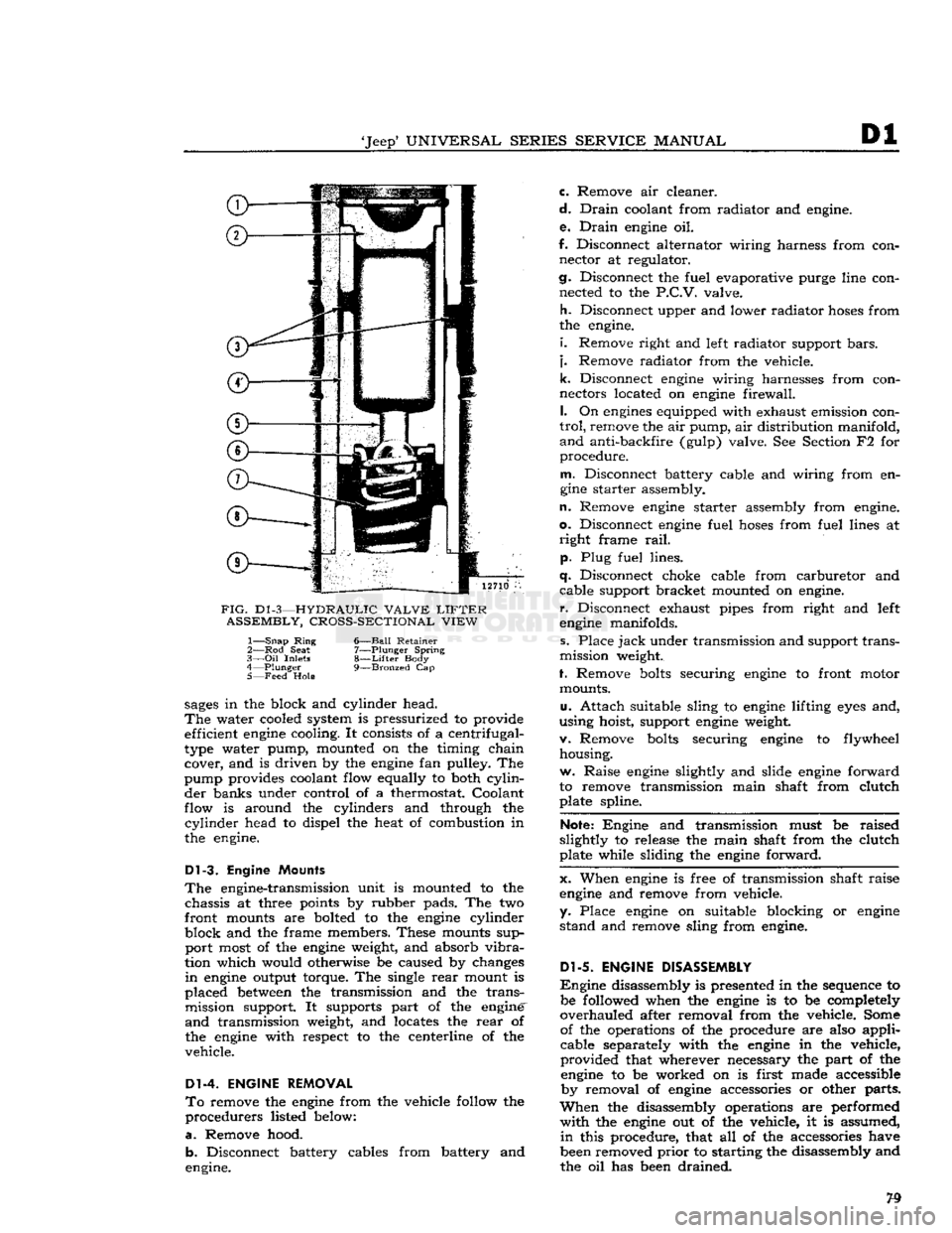
cushion of oil to absorb operating shocks. As shown in Fig. Dl-3, all parts of a hydraulic lifter
are
housed in the body, which is the cam follower.
At
the beginning of valve operation, the valve lifter body rests on the camshaft base circle.
Plunger
spring tension prevents lash clearances in the valve linkage.
As
the camshaft forces the valve lifter body up
ward,
both oil in the lower chamber and check
ball
spring
tension firmly seat the check ball against the plunger to prevent appreciable
loss
of oil from
the lower chamber. Oil pressure forces the plunger
upward,
with the body, to operate the valve linkage.
As
the camshaft rotates to closed-valve position, the valve spring forces the linkage and lifter down
ward.
When the
engine
valve seats, the linkage
parts
and plunger stop, but the plunger spring forces
the body downward .002" to .003"
[0,050
a
0,076
mm.] until it again rests on the camshaft base
circle.
Oil pressure then forces the check ball away
from
its seat and allows passage of oil past the check ball into the lower chamber.
This
replaces
the slight amount of oil lost by leakage. During
the valve opening and closing operation, a very
slight amount of oil escapes
between
plunger and body, and returns to the crankcase.
This
slight
loss
of oil (leak-down) is beneficial. It provides a
gradual
change of oil in the valve lifter; fresh oil
enters the lower chamber at the end of each cycle
of operation. 77
Page 79 of 376
'Jeep*
UNIVERSAL SERIES SERVICE
MANUAL
Dl
12710
FIG.
D1
-3—HYDRAULIC VALVE
LIFTER
ASSEMBLY, CROSS-SECTIONAL VIEW
1—
Snap
Ring
6—Ball Retainer
2— Rod
Seat
7—Plunger Spring
3—
Oil
Inlets
8—Lifter
Body
4—
Plunger
9—Bronzed
Cap
5— Feed
Hole
sages
in the block and cylinder head.
The
water cooled system is pressurized to provide efficient
engine
cooling. It consists of a centrifugal-
type water pump, mounted on the timing chain cover, and is driven by the
engine
fan pulley. The
pump provides coolant flow equally to both
cylin
der banks under control of a thermostat. Coolant
flow is around the cylinders and through the
cylinder
head to dispel the heat of combustion in
the engine.
Dl-3.
Engine Mounts
The
engine-transmission unit is mounted to the chassis at three points by rubber pads. The two
front mounts are bolted to the
engine
cylinder
block and the frame members. These mounts sup port most of the
engine
weight, and absorb
vibra
tion which would otherwise be caused by changes
in
engine
output torque. The single
rear
mount is
placed
between
the transmission and the trans mission support. It supports part of the engine'
and
transmission weight, and locates the
rear
of
the
engine
with respect to the centerline of the
vehicle.
Dl-4. ENGINE REMOVAL
To
remove the
engine
from the vehicle follow the
procedurers listed below:
a.
Remove hood. b. Disconnect battery cables from battery and
engine. c. Remove air cleaner.
d.
Drain
coolant from radiator and engine.
e.
Drain
engine
oil.
f. Disconnect alternator wiring harness from con nector at regulator.
cj.
Disconnect the fuel evaporative purge line con nected to the
P.C.V.
valve.
h.
Disconnect upper and lower radiator
hoses
from
the engine.
i.
Remove right and left radiator support
bars,
j.
Remove radiator from the vehicle.
k.
Disconnect
engine
wiring harnesses from con
nectors located on
engine
firewall.
I.
On
engines
equipped with exhaust emission con
trol,
remove the air pump, air distribution manifold,
and
anti-backfire (gulp) valve. See Section F2 for
procedure.
m.
Disconnect battery cable and wiring from en
gine
starter assembly.
n.
Remove
engine
starter assembly from engine,
o.
Disconnect
engine
fuel
hoses
from fuel lines at
right
frame
rail,
p. Plug fuel lines.
q.
Disconnect choke cable from carburetor and cable support bracket mounted on engine,
r.
Disconnect exhaust pipes from right and left
engine
manifolds.
s. Place
jack
under transmission and support trans
mission weight.
f. Remove
bolts
securing
engine
to front motor mounts.
u.
Attach suitable sling to
engine
lifting
eyes
and,
using hoist, support
engine
weight.
v. Remove
bolts
securing
engine
to flywheel housing.
w. Raise
engine
slightly and slide
engine
forward
to remove transmission main shaft from clutch plate spline.
Note:
Engine and transmission must be raised
slightly to release the main shaft from the clutch
plate while sliding the
engine
forward.
x. When
engine
is free of transmission shaft raise
engine
and remove from vehicle,
y. Place
engine
on suitable blocking or
engine
stand and remove sling from engine.
Dl-5.
ENGINE DISASSEMBLY
Engine
disassembly is presented in the sequence to be followed when the
engine
is to be completely
overhauled after removal from the vehicle. Some of the operations of the procedure are also applicable separately with the
engine
in the vehicle,
provided that wherever necessary the part of the
engine
to be worked on is first made accessible by removal of
engine
accessories or other parts.
When
the disassembly operations are performed
with
the
engine
out of the vehicle, it is assumed,
in
this procedure, that all of the accessories have
been removed
prior
to starting the disassembly and
the oil has been drained.
Page 81 of 376
'Jeep'
UNIVERSAL
SERIES
SERVICE
MANUAL
Dl
13296
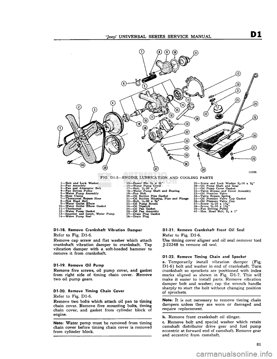
FIG.
Dl-5—ENGINE
LUBRICATION
AND
COOLING
PARTS
1— Bolt and
Lock
Washer
2—
Fan
Assembly
3—
Fan
and Alternator Belt
4—
Fan
Driven Pulley 5— Water Pump Assembly
6—
Hose
Clamp 7— Thermostat Bypass
Hose
8—Hex
Head Bolt
9— Water Outlet Elbow
10— Water Outlet Elbow Gasket
11— Thermostat
12— Water Pump Gasket
13— Impeller and Insert, Water Pump
14— Water Pump Seal 15— Dowel Pin % x Vfc"
16— Water Pump Cover
17— Bolt,
1/4-20
x 1"
18— Water Pump Shaft and Bearing
19—
Fan
Hub
20—
-Oil
Suction Pipe Gasket
21—
Oil
Suction Housing, Pipe and Flange
22— Bolt,
y4-20
x s/8"
23—
Oil
Pump Screen
24—
Oil
Dipstick
25—
Oil
Pan Gasket
26—
Oil
Pan Assembly
27—
Drain
Plug Gasket
28—
Drain
Plug 29— Screw and
Lock
Washer #6-18 x %
30—
Oil
Pump Shaft and Gear
31—
Oil
Pump Cover Gasket
32— Valve Bypass and Cover Assembly
33—
Oil
Pressure Valve 34— Valve Bypass Spring
35—
Oil
Pressure Valve Cap Gasket
36—
Oil
Pressure Valve Cap
37— Screw V4-20 x lVg"
38— Screw 1/4-20 x 1W' 39—
Fan
Driving Pulley
40— Hex. Head Bolt, x 1"
Dl-13.
Remove
Crankshaft
Vibration Damper
Refer
to Fig. Dl-6.
Remove cap screw and flat washer which attach
crankshaft
vibration damper to crankshaft. Tap
vibration
damper with a soft-headed hammer to remove it from crankshaft.
Dl-19.
Remove Oil Pump
Remove five screws, oil pump cover, and gasket
from
right side of timing chain cover. Remove
two oil pump gears.
D1-20.
Remove Timing Chain Cover
Refer
to Fig. Dl-6. Remove two
bolts
which attach oil pan to timing
chain
cover. Remove five mounting bolts, timing
chain
cover, and gasket from cylinder block of
engine.
Note:
Water pump must be removed from timing
chain
cover before timing chain cover is removed
from
cylinder block.
Dl-21.
Remove Crankshaft Front
Oil
Seal
Refer
to Fig. Dl-6.
Use timing cover aligner and oil seal remover
tool
J-22248 to remove oil seal.
Dl-22.
Remove Timing Chain
and
Spocket
a.
Temporarily install vibration damper (Fig.
Dl-6)
bolt and washer in end of crankshaft.
Turn
crankshaft
so sprockets are positioned with index
marks
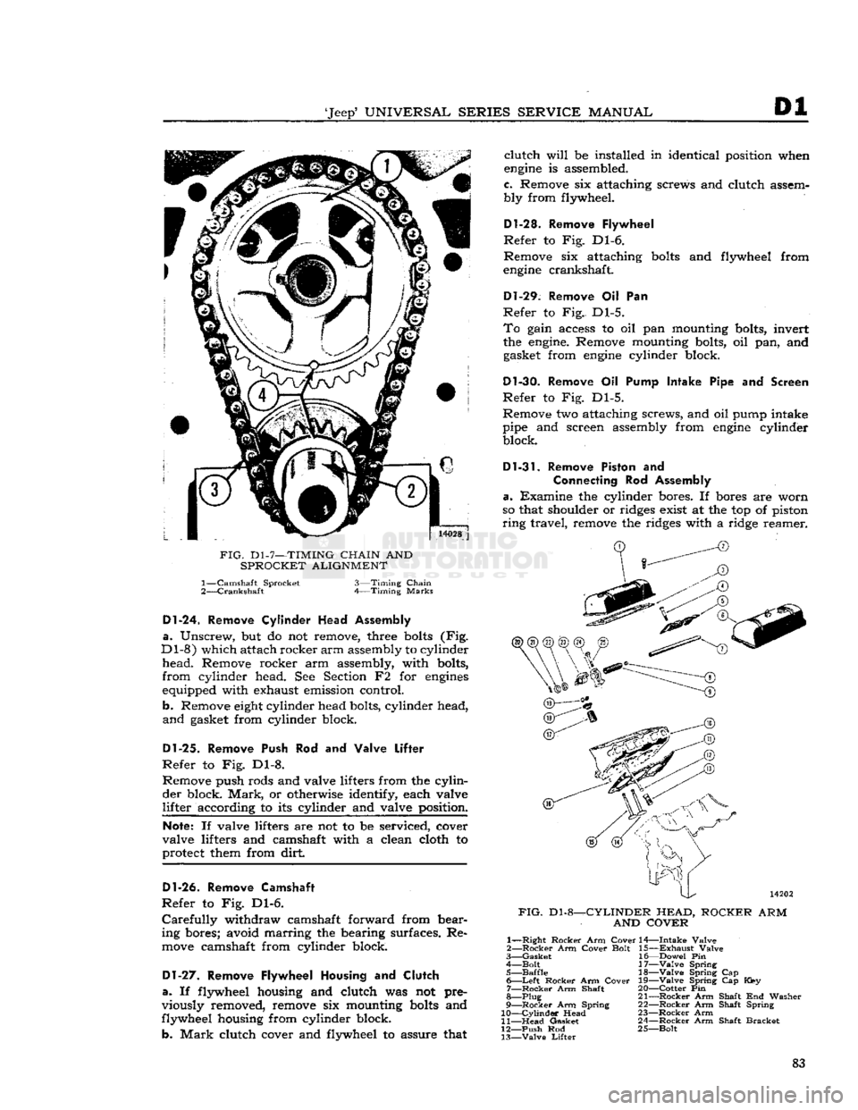
aligned as shown in Fig. Dl-7.
This
will
make it easier to install parts. Remove vibration
damper bolt and washer; rap the wrench handle
sharply
to start the bolt without changing position
of sprockets.
Note:
It is not necessary to remove timing chain
dampers unless they are worn or damaged and
require
replacement.
b. Remove front crankshaft oil slinger.
c. Remove bolt and special washer which retain
camshaft distributor drive gear and fuel pump
eccentric at forward end of camshaft. Remove gear
and
eccentric from camshaft. 81
Page 83 of 376
'Jeep'
UNIVERSAL
SERIES SERVICE
MANUAL
Dl
14028
j
FIG.
D1-7—TIMING
CHAIN
AND
SPROCKET ALIGNMENT 1—
Camshaft Sprocket
2—
Crankshaft
3—Timing
Chain
Timing
Marks
Dl-24.
Remove
Cylinder
Head Assembly
a.
Unscrew, but do not remove, three
bolts
(Fig.
Dl-8)
which attach rocker
arm
assembly to cylinder
head.
Remove rocker arm assembly, with bolts,
from
cylinder head. See Section F2 for
engines
equipped with exhaust emission control.
b. Remove
eight
cylinder head bolts, cylinder head,
and
gasket from cylinder block.
Dl-25.
Remove Push Rod and Valve
Lifter
Refer
to Fig. Dl-8. Remove push rods and valve lifters from the
cylin
der
block.
Mark,
or otherwise identify, each valve
lifter
according to its cylinder and valve position.
Note:
If valve lifters are not to be serviced, cover
valve lifters and camshaft with a clean cloth to
protect them from dirt
Dl-26.
Remove Camshaft
Refer
to Fig. Dl-6.
Carefully
withdraw camshaft forward from bear
ing bores; avoid marring the bearing surfaces. Re
move
camshaft from cylinder block.
Dl-27.
Remove Flywheel Housing and
Clutch
a.
If flywheel housing and clutch was not pre
viously removed, remove six mounting
bolts
and
flywheel housing from cylinder block.
b.
Mark
clutch cover and flywheel to assure that
clutch
will
be installed in identical position when
engine
is assembled.
c. Remove six attaching screws and clutch assem
bly from flywheel.
D1-28. Remove Flywheel
Refer
to Fig. Dl-6.
Remove six attaching
bolts
and flywheel from
engine
crankshaft.
Dl-29.
Remove Oil Pan
Refer
to Fig. Dl-5.
To
gain access to oil pan mounting bolts, invert
the
engine.
Remove mounting bolts, oil pan, and gasket from
engine
cylinder block.
Dl-30.
Remove Oil Pump Intake Pipe and Screen
Refer
to Fig. Dl-5.
Remove two attaching screws, and oil pump intake
pipe and screen assembly from
engine
cylinder block.
Dl-31.
Remove Piston and
Connecting
Rod Assembly
a.
Examine the cylinder bores. If bores are worn
so that shoulder or ridges exist at the top of piston
ring
travel, remove the ridges with a ridge reamer.
FIG.
Dl-8-
-CYLINDER HEAD,
AND COVER
ROCKER
ARM
1—
—Right
Rocker
Arm
Cover
2—
Rocker
Arm
Cover
Bolt
3—
Gasket
4—
Bolt
5—
Baffle
6—
Left
Rocker
Arm
Cover
7—
Rocker
Arm Shaft
8—Plug
9—
Rocker
Arm Spring
10—
Cylinder
Head
11—
Head
Gasket
12—
Push
Rod
13—
Valve
Lifter
14—
Intake
Valve
15—
Exhaust
Valve
16—
Dowel
Pin
17—
Valve
Spring 18—
Valve
Spring Cap
19—
Valve
Spring Cap Key
20—
Cotter
Pin
21—
Rocker
Arm Shaft End Washer
22—
Rocker
Arm Shaft Spring
23—
Rocker
Arm
24—
Rocker
Arm Shaft
Bracket
25—
Bolt
83
Page 85 of 376
'Jeep*
UNIVERSAL
SERIES SERVICE
MANUAL
Dl
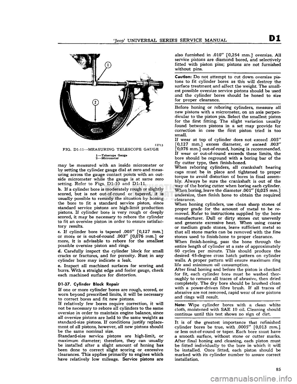
12713
FIG.
Dl-11—MEASURING
TELESCOPE GAUGE
1—
Telescope
Gauge
2—
Micrometer
may
be measured with an inside micrometer or
by setting the cylinder
gauge
dial
at zero and meas
uring
across the
gauge
contact points with an outside micrometer while the
gauge
is at same zero
setting. Refer to
Figs.
Dl-10 and Dl-11.
b.
If a cylinder bore is moderately rough or slightly
scored,
but is not out-of-round or tapered, it is
usually
possible to remedy the situation by honing
the bore to fit a standard service piston, since
standard
service pistons are high-limit production
pistons. If cylinder bore is very rough or deeply
scored,
it may be necessary to rebore the cylinder
to fit an oversize piston in order to ensure satisfac
tory
results.
c.
If cylinder bore is tapered .005" [0,127 mm.]
or
more or is out-of-round .003" [0,076 mm.] or
more,
it is advisable to rebore for the smallest possible oversize piston and rings.
d.
Carefully
inspect the cylinder block for small
cracks
or fractures, and for porosity.
Rust
in any
cylinder
bore may indicate a leak.
e.
Inspect all machined surfaces for scoring and
burrs.
With
a straight
edge
and feeler
gauge,
check
each
machined surface for distortion.
D1-37.
Cylinder Block Repair
If
one or more cylinder bores are rough, scored, or
worn
beyond prescribed limits, it
will
be necessary
to correct bores and fit new pistons.
If
relatively few bores require correction, it
will
not be necessary to rebore all cylinders to the same
oversize in order to maintain
engine
balance, since
all
oversize pistons are held to the same weights as
standard-size
pistons. If conditions justify replace
ment of all pistons, however, all new pistons should
be the same nominal size.
Standard-size
service pistons are high-limit, or
maximum
diameter; therefore, they can usually be installed after a slight amount of honing has
been
done
to correct slight scoring or excessive
clearances.
This
applies
primarily
to
engines
which
have relatively low mileage. Service pistons are also furnished in .010"
[0,254
mm.] oversize. All
service
pistons are diamond bored, and selectively
fitted with piston pins; pistons are not furnished
without pins.
Caution:
Do not attempt to cut down oversize pis
tons
to fit cylinder bores as this
will
destroy the
surface
treatment and affect the weight. The small
est possible oversize service pistons should be used
and
the cylinder bores should be honed to size
for
proper clearance.
Before
honing or reboring cylinders, measure all new pistons with a micrometer, on an axis perpen
dicular
to the piston pin. Select the smallest piston
for
the first fitting. The slight variation usually
found between pistons in a set may provide for
correction
in case the first piston tried is too
small.
If
wear at top of cylinder
does
not exceed .005" [0,127 mm.]
excess
diameter, or exceed .003"
[0,076 mm.] out-of-round, honing is recommended.
If
wear or out-of-round
exceeds
these
limits, the
bore should be reground with a boring bar of the
fly
cutter type, then finish-honed.
When
reboring cylinders, all crankshaft bearing caps must be in place and tightened to proper
torque to avoid distortion of bores in
final
assem
bly.
Always be sure the crankshaft is out of the
way
of the boring cutter when boring each cylinder.
When
boring, leave the diameter .001" [0,025 mm.]
undersize,
then finish hone to obtain the required
clearance.
When
honing cylinders, use clean sharp
stones
of
proper
grade for the amount of metal to be re
moved. Refer to instructions supplied by the hone
manufacturer.
Dull
or dirty
stones
cut unevenly
and
generate excessive heat. When using coarse
or
medium grade
stones,
leave sufficient metal so
that all
stone
marks can be removed with the fine
stones
used to finish-hone to proper clearance.
When
finish-honing, pass the hone through the entire length of cylinder at a rate of approximately 60 cycles per minute.
This
should produce the
desired
45-degree
cross hatch pattern on cylinder
walls.
A proper pattern
will
ensure maximum
ring
life and minimum oil consumption.
After
final
honing and before the piston is checked
for
fit, each cylinder bore must be washed thor oughly to remove all traces of abrasive, then dried completely. The dry bore should be brushed clean
with
a power-driven fibre
brush.
If all traces of
abrasive
are not removed,
rapid
wear of new pistons
and
rings
will
result.
Note:
Wipe cylinder bores with a clean white
cloth,
moistened with SAE 10 oil. Cleaning should
continue until this
test
shows no sign of
dirt.
It
is of the greatest importance that refinished
cylinder
bores be true, with .0005" [0,013 mm.]
or
less out-of-round or taper.
Each
bore must have
a
smooth surface, without
stone
or cutter
marks.
After
final
honing and cleaning, each piston must be fitted individually to the bore in which it
will
be installed. Once fitted, each piston should be
marked
with its cylinder number to assure correct
installation.
85
Page 86 of 376
Dl
DAUNTLESS
V-6
ENGINE
Dl-38.
Crankshaft
Cleaning
Clean
the crankshaft thoroughly with a suitable
cleaning solvent.
Clean
drilled oil
passages
in its
journals
with a small rifle brush to remove all
sludge
or gum deposits; dry
passages
with com
pressed air.
Dl-39.
Crankshaft
Inspection
and
Repair
If
the crankshaft has not
been
removed from the
cylinder
block for inspection, disconnect two con necting rods at a time from crankshaft. Inspect
the bearings and crankpin journals. While turning
crankshaft,
it is necessary to temporarily reconnect
the rods to crankshaft to avoid possibility of dam aging the journals through contact with uncon
nected rods.
Inspect the crankpins visually for excessive or ir
regular
wear, and for scoring. Use an
outside
micrometer to check crankpins for out-of-round.
Standard
crankpin
diameter is
2.0000"
[5,080
cm.].
If
crankpins are more than .0015"
[0,0381
mm.]
out-of-round, new bearings cannot be
expected
to
have satisfactory life.
If
the crankshaft has
been
removed from the
cyl
inder
block for inspection support it on V-blocks
at its main bearing journals 1 and 4. Inspect the
main
bearing journals visually for excessive or ir
regular
wear, and for scoring. Standard main bear
ing
journal
diameter is 2.4995"
[6,349
cm.].
Total
indicator readings at each
journal
should not ex
ceed .003"
[0,076
mm.].
Check
run out at all four journals and
note
high
spot
(maximum eccentricity) of each
journal.
High
spot
of each
journal
should
come
at the same
angular
location. If high
spots
do not coincide,
crankshaft
is misaligned and unsatisfactory for
service.
If
crankpin or main bearing journals are scored,
ridged, or out-of-round, the crankshaft must be replaced or reground to a standard undersize bear
ing diameter to ensure satisfactory life of bearings. Slight roughness can be removed with a fine grit
polishing cloth thoroughly
wetted
with
engine
oil.
Burrs
can
be
honed with a fine oil
stone,
so long as
bearing clearances
will
remain within specified
limits.
Dl-40.
Crankshaft
Main
Bearings
A
crankshaft bearing consists of two halves which
are
neither alike nor interchangeable. One half is
carried
in the corresponding main bearing cap; the
other half is located
between
the crankshaft and
cylinder
block. The upper (cylinder block) half
of the bearing is grooved to supply oil to the con necting rod bearings, while the lower (bearing cap)
half
of the bearing is not grooved. The two bearing
halves must not be interchanged. All crankshaft
bearings
except
the thrust bearing and the
rear
main
bearing are identical. The thrust bearing (No. 2) is longer and it is flanged to take
crank
shaft end thrust. When the bearing halves are
placed in cylinder block and bearing cap, the
ends
extend slightly beyond the parting surfaces. When
cap
bolts
are tightened, the halves are clamped
tightly in place to ensure positive seating and to
prevent turning. The
ends
of bearing halves must never be filed flush with parting surface of
crank
case or bearing cap.
Crankshaft
bearings are the precision type which
do not require reaming to size or other fitting.
Shims
are not provided for adjustment since worn
bearings are readily replaced with new bearings of proper size. Bearings for service replacement are
furnished
in standard size and undersizes. Under no circumstances should crankshaft bearing caps
be filed to adjust for wear in old bearings.
Dl-41.
Crankshaft
Main
Bearing
Cleaning
and
Inspection
Clean
main bearing surfaces. Inspect the bearings
visually
for excessive or uneven wear, scoring, and
flaking.
Visibly worn or damaged bearings must
be replaced. It is necessary to check
radial
clear ance of each new or used crankshaft main bearing
before installation.
This
can be
done
by either of two methods, which are described in
Pars.
Dl-42
and
Dl-43.
a.
The desired
radial
clearance of a new bearing
is .0005" to .0021"
[0,0127
a
0,0534
mm.].
b. Replacement bearings are furnished in standard
size, and in several undersizes, including undersizes
for reground journals. If a new bearing is to be installed, try a standard size; then try each under
size in turn until one is found that
meets
the
specified clearance limits.
Note:
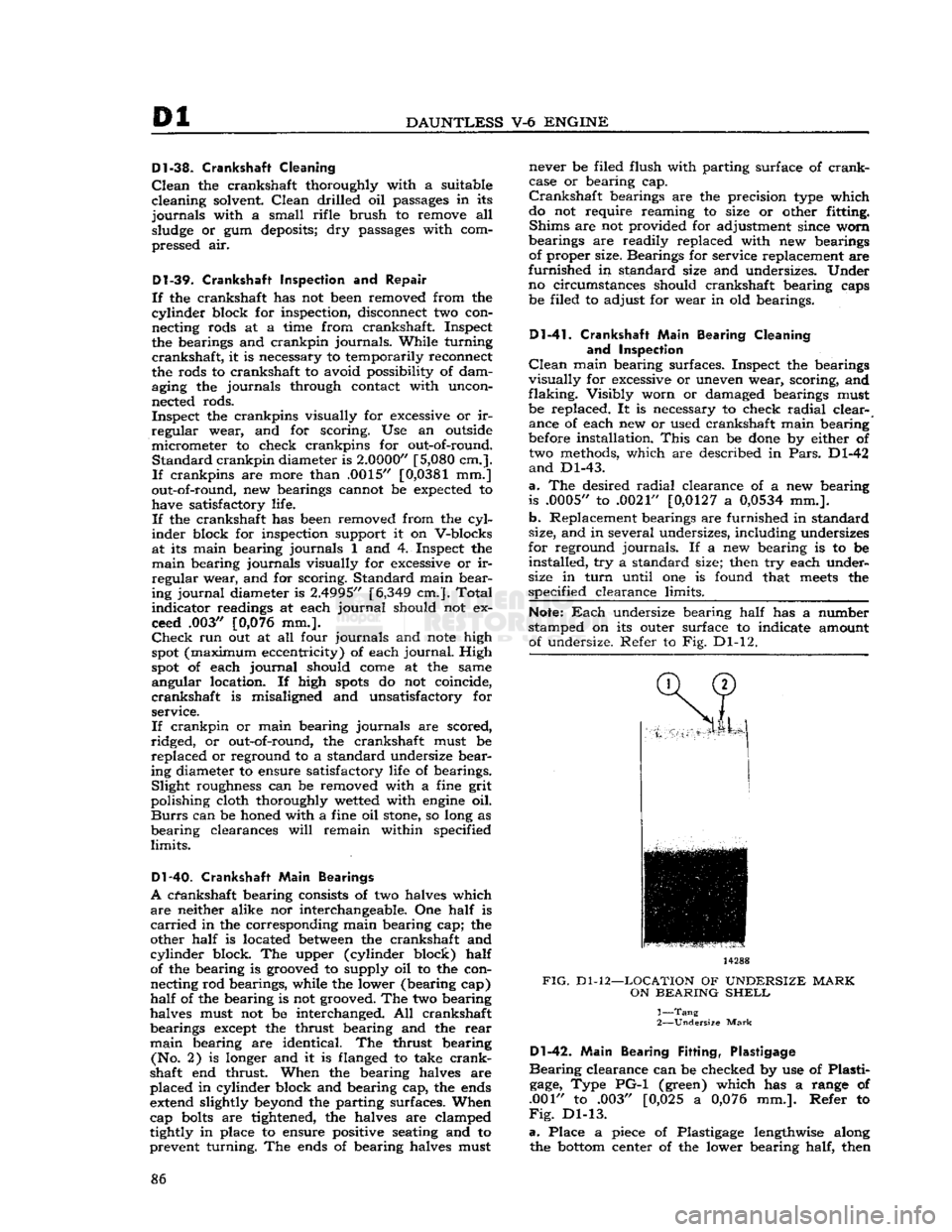
Each
undersize bearing half has a number
stamped on its outer surface to indicate amount of undersize. Refer to Fig. Dl-12. 14288
FIG.
Dl-12—LOCATION
OF
UNDERSIZE
MARK
ON
BEARING
SHELL
1—
Tang
2—
Undersize
Mark
Dl-42.
Main
Bearing
Fitting,
Plastigage
Bearing
clearance can be checked by use of Plasti
gage,
Type PG-1 (green) which has a range of
.001" to .003" [0,025 a
0,076
mm.]. Refer to
Fig.
Dl-13.
a.
Place a piece of Plastigage lengthwise along the
bottom
center of the lower bearing half, then 86