instrument panel JEEP CJ 1953 Service Manual
[x] Cancel search | Manufacturer: JEEP, Model Year: 1953, Model line: CJ, Model: JEEP CJ 1953Pages: 376, PDF Size: 19.96 MB
Page 10 of 376
B
LUBRICATION
B-2.
Special Lubricants
Special
lubricants are required for certain
lubri
cation points on the 'Jeep' Universal vehicles. The
special
lubricants are necessary for proper function ing and maintenance of the vehicle. The
Lubrica
tion
Chart
(Fig. B-l and B-2)
designates
the spe
cial
lubricating points and identifies them by type
or
part number.
B-3.
Applying
Fresh
Lubricant
When
servicing or lubricating the vehicle, it is important that all old lubricant and
dirt
be re moved from the fitting and/or plugs before servic
ing and that the recommended type of lubricant be used for the particular item being serviced.
Force
lubricant through the lube fittings until the lubricant being forced out of the joint is fresh
lubricant,
indicating that all old lubricant has
been removed.
B-4.
Engine
Lubrication
System —
Hurricane
F4 Engine
•
Refer to Fig. B-3.
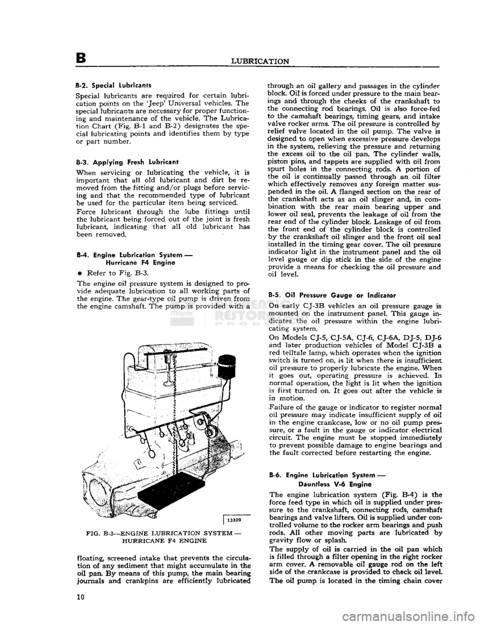
The
engine
oil pressure system is designed to pro
vide adequate lubrication to all working parts of
the engine. The gear-type oil pump is driven from
the
engine
camshaft. The pump is provided with a
FIG.
B-3—ENGINE
LUBRICATION
SYSTEM
—
HURRICANE
F4
ENGINE
floating, screened intake that prevents the
circula
tion of any sediment that might accumulate in the
oil
pan. By means of this pump, the main bearing
journals
and crankpins are efficiently lubricated through an oil gallery and passages in the cylinder
block.
Oil
is forced under pressure to the main bear
ings and through the cheeks of the crankshaft to
the connecting rod bearings. Oil is also force-fed
to the camshaft bearings, timing gears, and intake valve rocker arms. The oil pressure is controlled by
relief
valve located in the oil pump. The valve is
designed to open when excessive pressure
develops
in
the system, relieving the pressure and returning the
excess
oil to the oil pan. The cylinder walls,
piston pins, and tappets are supplied with oil from
spurt
holes
in the connecting rods. A portion of the oil is continually passed through an oil filter
which
effectively removes any foreign matter sus pended in the oil. A flanged section on the
rear
of
the crankshaft acts as an oil slinger and, in com
bination with the
rear
main bearing upper and lower oil seal, prevents the leakage of oil from the
rear
end of the cylinder block. Leakage of oil from
the front end of the cylinder block is controlled by the crankshaft oil slinger and the front oil seal
installed in the timing gear cover. The oil pressure
indicator
light in the instrument panel and the oil level
gauge
or dip stick in the side of the
engine
provide a means for checking the oil pressure and
oil
level.
B-5.
Oil Pressure Gauge or Indicator
On
early
CJ-3B
vehicles an oil pressure
gauge
is
mounted on the instrument panel.
This
gauge
in dicates the oil pressure within the
engine
lubri
cating system.
On
Models
CJ-5,
CJ-5A,
CJ-6,
CJ-6A,
DJ-5, DJ-6
and
later production vehicles of Model
CJ-3B
a
red
telltale lamp, which operates when the ignition
switch is turned on, is lit when there is insufficient
oil
pressure to properly lubricate the engine. When
it
goes
out, operating pressure is achieved. In
normal
operation, the light is lit when the ignition
is first turned on. It
goes
out after the vehicle is
in
motion.
Failure
of the
gauge
or indicator to register normal
oil
pressure may indicate insufficient supply of oil
in
the
engine
crankcase, low or no oil pump pres
sure,
or a fault in the
gauge
or indicator electrical
circuit.
The
engine
must be stopped immediately to prevent possible damage to
engine
bearings and
the fault corrected before restarting the engine.
B-6.
Engine
Lubrication
System — Dauntless V-6 Engine
The
engine
lubrication system (Fig. B-4) is the
force
feed
type in which oil is supplied under pres
sure
to the crankshaft, connecting rods, camshaft bearings and valve lifters. Oil is supplied under controlled volume to the rocker arm bearings and push
rods.
All other moving parts are lubricated by gravity flow or splash.
The
supply of oil is
carried
in the oil pan which is filled through a filter opening in the right rocker
arm
cover. A removable oil
gauge
rod on the left side of the crankcase is provided to check oil level.
The
oil pump is located in the timing chain cover 10
Page 17 of 376
'Jeep'
UNIVERSAL SERIES SERVICE
MANUAL
B
Reinstall
the axle shafts, and
refill
the housings to
plug level using the universal joint lubricant
specified in
Lubrication
Specifications.
B-56.
Front
Axle Wheel Bearings
To
lubricate the wheel bearings, it is necessary
to remove, clean, repack, and adjust them. When
front wheel hubs and bearings are removed for
lubrication,
they should be thoroughly washed in a
suitable cleaning solvent. The bearings should be
carefully
dried and then given a thorough cleaning
and
inspection. Use a clean brush to remove all
particles
of old lubricant from bearings and hubs.
After
the bearings are cleaned, inspect them for
pitted races and rollers. Also, check the hub oil
seals.
Note:
Wheel bearing lithium base lubricants are
used at the factory for
initial
fill
of
these
bearings.
When
lithium base and sodium base lubricants are
mixed,
the result is a thinned-out mixture that
can
bleed through seals. It is therefore important
that lubricants with the correct base be used when
lubricating
the wheel bearings.
Should
leaks occur at wheel bearing seals, the leaks
may
be caused by a mixture of two
types
of
lubri
cants.
In such cases, the old lubricant should be
completely removed before new lubricant is added.
Wheel
bearings should be thoroughly cleaned,
lubricated
with lithium base and reinstalled.
Repack
the bearing
cones
and rollers with grease
and
reassemble hub in the reverse order of the
disassembly. Test the bearing adjustment as out
lined
in Section Q.
B-57.
Rear
Axle Wheel Bearings
The
Rear
wheel bearings an early models equipped
with
lubrication fittings with a vent opening
through the housings above each fitting should be
lubricated
sparingly, each
2,000
miles
[3.200
km.].
Use
a hand compressor and wheel bearing grease,
forcing
the grease through each lubrication fitting
until
it flows from the vent. Vent should be kept
clear
of obstruction or grease
will
back up into the
brakes.
Do not add grease after it flows from the
vent for it may be forced through the wheel key-
way
onto
the outside of the wheel and possibly
onto
the brake linings.
Rear
wheel bearings that do
not have lubrication fittings should be removed
each
12,000
miles
[19.200
km.] and the bearing
cleaned, inspected and repacked. Refer to proce
dure
in Par. B-56.
Note:
When servicing the Flanged Axle Unit
Bear
ing Assembly, refer to Section N, Par. N-5 for
proper
lubrication procedures.
B-58.
Propeller Shafts
and
Universal Joints
The
propeller shaft slip joints and universals should
be lubricated with a hand compressor grease gun so as to not damage the bearing seals. The units
should be lubricated with a
good
quality grease.
Refer
to the
Lubrication
Chart
for lubrication fre
quency and lubricant type and grade. B-59.
Lights
and
Controls
a.
Check
all interior and exterior lights and light
switches for proper operation, including: parking
lights, headlamps (high beam and low beam),
tail
lights, brake lights, directional lights, and in strument panel lights.
b.
Check
all instrument panel controls and
instru
ments for proper operation.
B-60.
Speedometer Cable
Remove the
speedometer
cable from its housing every
12,000
miles
[19.300
km.].
Clean
it thor
oughly and coat it with a
good
quality light graphite grease.
B-61.
Headlights
Refer
to Section H.
B-62.
Heater Controls
Apply
Lubriplate
130-A to all friction points and
pivot points on the heater controls panel unit as well as the pivot points at the dashpot. Apply
a
few drops of penetrating oil all along the Bowden
cable.
This
oil
will
penetrate into the center wire.
B-63.
Windshield Wiper and
Washer Controls
Lubricate
the friction points and the pivot points
on the windshield wiper transmission and linkage
arms
with a slight amount of
Lubriplate
130-A.
B-64.
Rotate Tires
Refer
to Section Q for the correct method of rotat ing the tires.
B-65.
Body Lube Points
•
Refer to Par. B-66 through B-68.
B-66.
Hood Hinge Pivot Points
Lubricate
the frictional points of the hood hinge
pivot points with a few drops of light-weight
engine
oil.
B-67.
Glove Compartment Door Latch
Sparingly
wipe
Lubriplate
130-A on the
glove
com
partment door latch.
B-68.
Tailgate Hinges
Lubricate
the friction points of the tailgate hinges
with
a few drops of light-weight
engine
oil.
B-69.
LUBRICATION
OF
OPTIONAL EQUIPMENT
B-70.
Pintle Hook
When
lubricating the vehicle, place a few drops of oil on the pintle hook and safety latch pivot pins.
B-7!.
Centrifugal Governor
Check
the oil level in the governor housing at each
vehicle lubrication. Use the same seasonal grade
oil
as is used in the
engine
and change oil at each
engine
oil change. Do not
fill
the housing above
the level indicating plug opening. Keep the vent
in
the filler plug open at all times. 17
Page 166 of 376
G
COOLING SYSTEM and
the outlet
hose
is connected to the water pump
housing.
When
installing a new hose, clean the pipe connec
tions and apply a thin layer of nonhardening seal
ing compound. Hose clamps should be properly
located over the connections to provide secure fastening. The pressurized cooling system pressure
can
blow off improperly installed hoses.
G-8.
Cylinder
Block
Any
coolant leaks at the engine block water joints
are
aggravated by pump pressure in the water
jacket
and by pressure developed in the cooling system when the pressure cap is in place.
Small
leaks showing up only as moist
spots
often
cannot
be detected when the engine is hot except by the
appearance of rust, corrosion, and dye stains where
leakage evaporated. Also, expansion and contrac tion of the engine block resulting from extreme
temperature changes can aggravate leaks. For
these
reasons, when checking for coolant leaks inspect
the block when it is cold and while the engine is
running.
A
leaking
drain
cock or plug that cannot be stopped
leaking
by tightening should be replaced.
Leaking
core-hole expansion plugs should be replaced.
If
tightening gasketed joints
will
not correct leak
age, install new gaskets. Use a sealing compound
where recommended.
G-9.
Thermostat
a.
The cooling system of the engine is designed
to provide adequate cooling under most adverse conditions. However, it is necessary to employ
some
device to provide quick warming and to prevent
overcooling during normal operation. Automatic
control
of engine operating temperature is provided
by a water flow control thermostat installed in the
water
outlet of the
Hurricane
F4 engine. The ther
mostat is a heat-operated valve. It should always
be maintained in working order and the vehicle
should never be driven without one installed as there would then be no control of engine tempera
ture.
The temperature at which the thermostat
opens
is preset and cannot be altered.
b.
The thermostat on the
Hurricane
F4 engine is
located in a housing on the top front of the cylinder
head.
On the Dauntless V-6 engine it is located
in
the thermostat housing of the air intake manifold.
The
standard engine thermostat for the
Hurricane
F4
and Dauntless V-6 engine has a normal rating
of
190°F.
[87.8°C]
and should begin to open at
a
coolant temperature between
180°F.
[82°C]
to
192°F.
[89°C]
and be fully open at
202°F.
[94°C.].
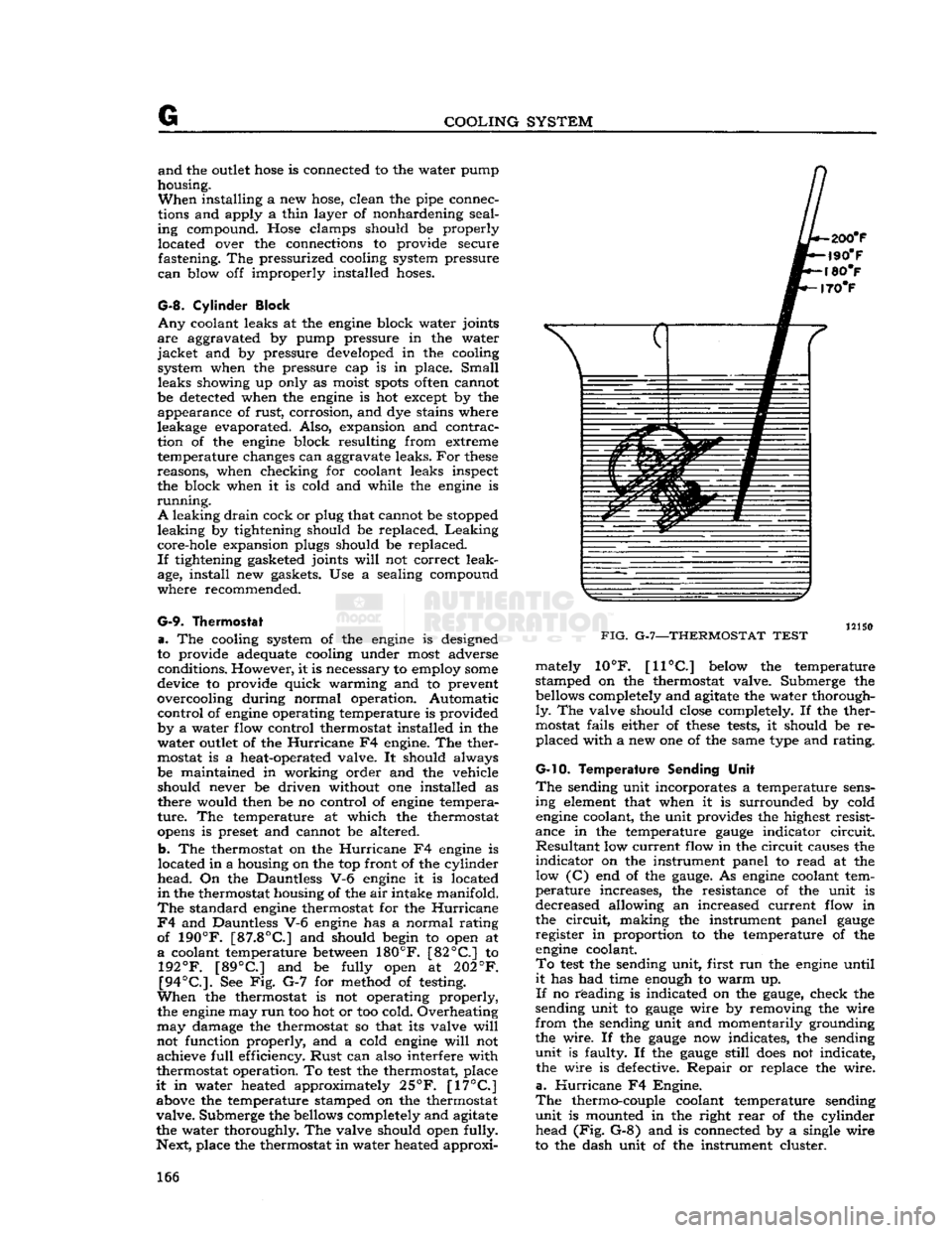
See Fig. G-7 for method of testing.
When
the thermostat is not operating properly, the engine may
run
too hot or too cold. Overheating
may
damage the thermostat so that its valve
will
not function properly, and a cold engine
will
not achieve
full
efficiency.
Rust
can also interfere with
thermostat operation. To
test
the thermostat, place
it
in water heated approximately
25°F.
[17°C]
above the temperature stamped on the thermostat
valve.
Submerge the bellows completely and agitate
the water thoroughly. The valve should open fully.
Next, place the thermostat in water heated approxi-
FIG.
G-7—THERMOSTAT
TEST
mately 10°F.
[11°C]
below the temperature
stamped on the thermostat valve. Submerge the bellows completely and agitate the water thorough
ly.
The valve should close completely. If the ther
mostat fails either of
these
tests, it should be re placed with a new one of the same type and rating.
G-10. Temperature
Sending Unit
The
sending unit incorporates a temperature sens ing element that when it is surrounded by cold engine coolant, the unit provides the highest resist
ance in the temperature
gauge
indicator
circuit.
Resultant
low current flow in the circuit causes the
indicator
on the instrument panel to read at the low (C) end of the
gauge.
As engine coolant tem
perature
increases, the resistance of the unit is
decreased allowing an increased current flow in
the
circuit,
making the instrument panel
gauge
register in proportion to the temperature of the engine coolant.
To
test
the sending unit, first run the engine until
it
has had time enough to warm up.
If
no reading is indicated on the
gauge,
check the
sending unit to
gauge
wire by removing the wire
from
the sending unit and momentarily grounding
the wire. If the
gauge
now indicates, the sending
unit
is faulty. If the
gauge
still
does
not indicate, the wire is defective.
Repair
or replace the wire,
a.
Hurricane
F4 Engine.
The
thermo-couple coolant temperature sending
unit
is mounted in the right
rear
of the cylinder head (Fig. G-8) and is connected by a single wire
to the dash unit of the instrument cluster. 166
Page 177 of 376
'Jeep*
UNIVERSAL
SERIES
SERVICE
MANUAL
H
12968
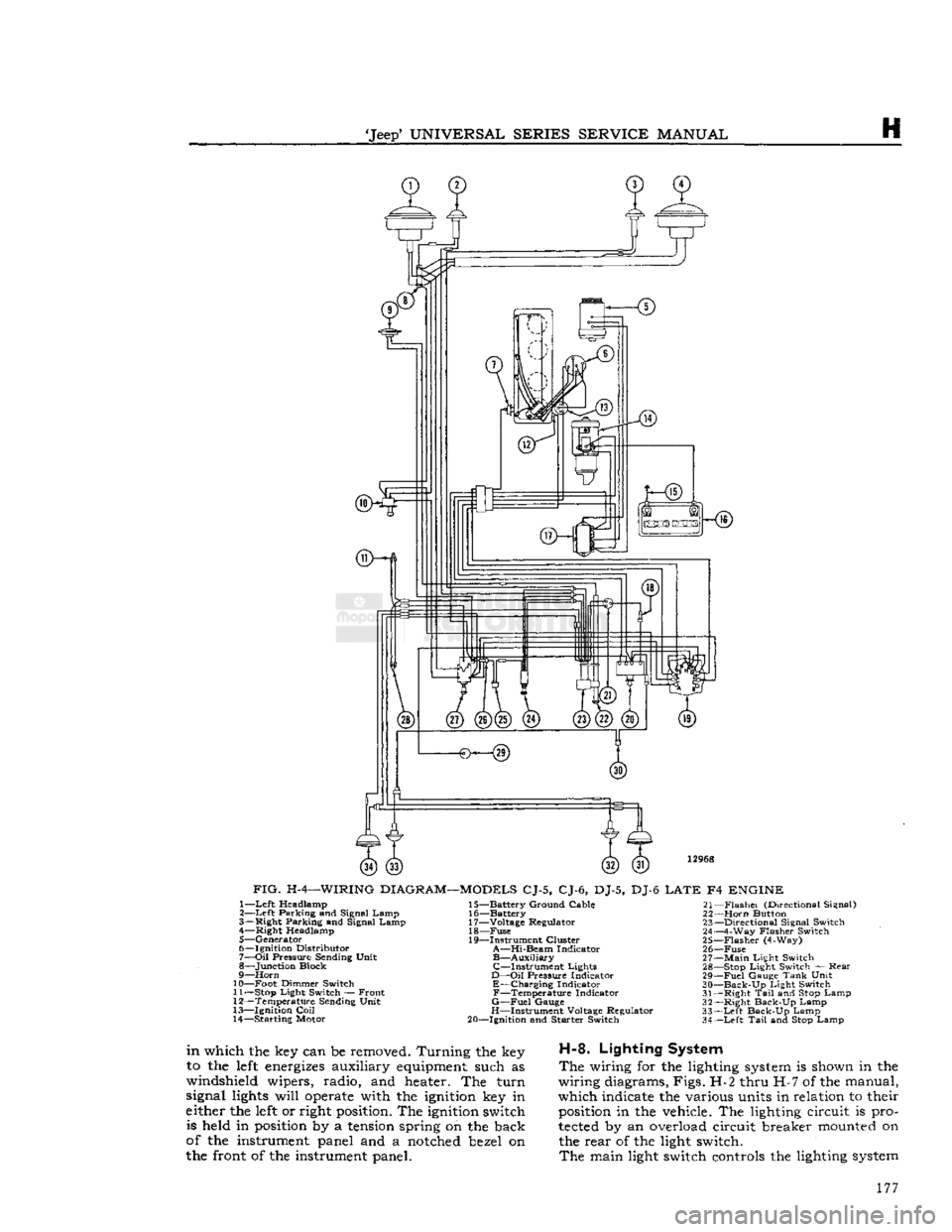
FIG.
H-4—WIRING
DIAGRAM—MODELS
CJ-5, CJ-6, DJ-5, DJ-6
LATE
F4
ENGINE
1—
Left
Headlamp
2—
Left
Parking and Signal Lamp
3— Right Parking and Signal Lamp 4— Right Headlamp
5— Generator
6— Ignition Distributor
7—
Oil
Pressure Sending Unit
8— Junction Block
9—
Horn
10— Foot Dimmer Switch 11—
Stop
Light Switch — Front
12— Temperature Sending Unit
13— Ignition
Coil
14— Starting Motor 15— Battery Ground Cable
16— Battery
17— Voltage Regulator 18—
Fuse
19— Instrument Cluster
A—Hi-Beam
Indicator
B—Auxiliary
C—Instrument
Lights
D—Oil
Pressure Indicator
E—Charging
Indicator
F—Temperature
Indicator
G—Fuel
Gauge
H—Instrument Voltage Regulator
20— Ignition and Starter Switch 21—
Flashei
(Directional Signal)
22—
Horn
Button 23— Directional Signal Switch
24— 4-Way Flasher Switch
25—
Flasher
(4-Way)
26—
Fuse
27—
Main
Light Switch 28—
Stop
Light Switch — Rear
29—
Fuel
Gauge
Tank
Unit
30—
Back-Up
Light Switch
31— Right
Tail
and
Stop
Lamp
32— Right Back-Up Lamp
33—
Left
Back-Up Lamp
34—
Left
Tail
and
Stop
Lamp
in
which the key can be removed. Turning the key
to the
left
energizes
auxiliary
equipment
such as
windshield wipers, radio, and heater. The turn
signal
lights
will
operate
with the
ignition
key in
either the
left
or right
position.
The
ignition
switch is held in
position
by a
tension
spring on the back
of the instrument panel and a
notched
bezel on
the front of the instrument panel.
H-8.
Lighting System
The
wiring for the lighting
system
is shown in the
wiring diagrams, Figs. H-2 thru H-7 of the manual,
which indicate the various units in relation to their
position
in the vehicle. The lighting circuit is pro
tected
by an overload circuit breaker
mounted
on the rear of the light switch.
The
main light switch controls the lighting
system
177
Page 178 of 376
H
ELECTRICAL
SYSTEM
14365
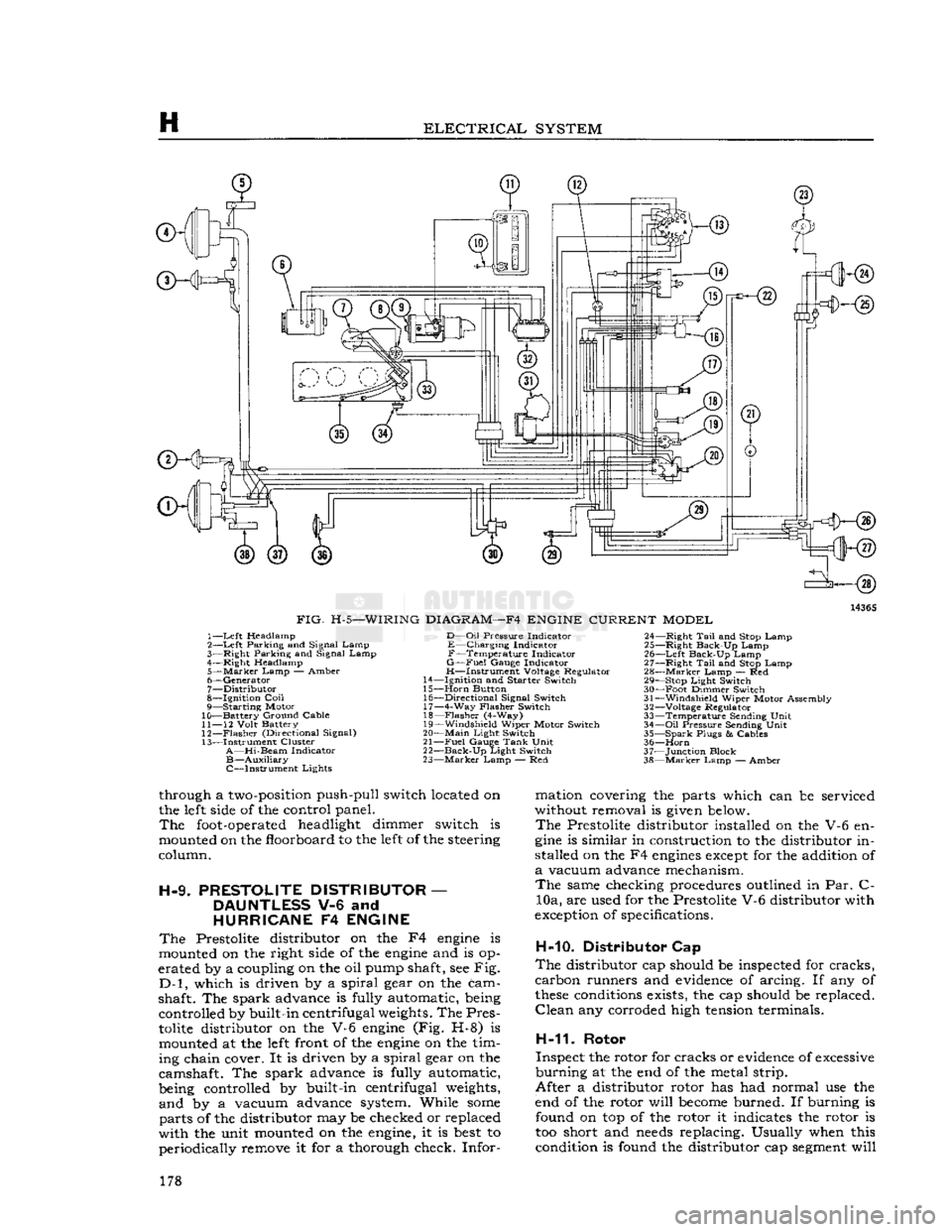
FIG.
H-5—WIRING
DIAGRAM—F4
ENGINE
CURRENT
MODEL
1—
Left
Headlamp
2—
Left
Parking and Signal Lamp
3—
Right
Parking and Signal Lamp
4—
Right
Headlamp
5—
Marker
Lamp
— Amber
6—
Generator
7—
Distributor
8—
Ignition
Coil
9— Starting Motor
10— Battery Ground Cable
11—
12
Volt
Battery
12—
Flasher
(Directional Signal)
13— Instrument Cluster
A—Hi-Beam
Indicator
B—Auxiliary
C—Instrument Lights
D—Oil
Pressure
Indicator
E—Charging Indicator
F—Temperature Indicator
G—Fuel
Gauge
Indicator
H—Instrument Voltage Regulator
14—
Ignition
and
Starter
Switch
15—
Horn
Button 16—
Directional
Signal Switch 17— 4-Way
Flasher
Switch
18—
Flasher
(4-Way)
19—
Windshield
Wiper Motor Switch
20—
Main
Light
Switch
21—
Fuel
Gauge
Tank
Unit
22—
Back-Up
Light
Switch
23—
Marker
Lamp — Red 24—
Right
Tail
and Stop Lamp
25—
Right
Back-Up Lamp
26—
Left
Back-Up Lamp
27—
Right
Tail
and Stop Lamp
28—
Marker
Lamp — Red 29— Stop
Light
Switch
30— Foot Dimmer Switch
31—
Windshield
Wiper Motor Assembly
32—
Voltage Regulator
33— Temperature Sending
Unit
34—
Oil
Pressure
Sending
Unit
35— Spark
Plugs
&
Cables
36—
Horn
37— Junction Block
38—
Marker
Lamp — Amber
through a
two-position
push-pull switch located on
the
left
side
of the control panel.
The
foot-operated
headlight dimmer switch is
mounted on the floorboard to the
left
of the steering
column.
H-9.
PRESTOLITE
DISTRIBUTOR
—
DAUNTLESS
V-6 and
HURRICANE
F4
ENGINE
The
Prestolite distributor on the F4
engine
is
mounted on the right
side
of the
engine
and is op
erated by a coupling on the oil pump shaft, see Fig.
D-l,
which is driven by a spiral gear on the cam
shaft. The spark advance is fully automatic, being controlled by built-in centrifugal
weights.
The Pres
tolite
distributor on the V-6
engine
(Fig. H-8) is mounted at the
left
front of the
engine
on the tim
ing chain cover. It is driven by a spiral gear on the
camshaft. The spark advance is fully automatic,
being controlled by built-in centrifugal
weights,
and by a vacuum advance system. While
some
parts of the distributor may be checked or replaced
with the unit mounted on the
engine,
it is
best
to periodically remove it for a thorough check. Infor mation covering the parts which can be serviced
without removal is
given
below.
The
Prestolite distributor installed on the V-6 en
gine
is similar in construction to the distributor in
stalled on the F4
engines
except
for the addition of
a
vacuum advance mechanism.
The
same checking procedures outlined in Par. C- 10a, are used for the Prestolite V-6 distributor with
exception
of specifications.
H-10. Distributor Cap
The
distributor cap should be inspected for cracks,
carbon runners and
evidence
of arcing. If any of
these
conditions
exists, the cap should be replaced.
Clean
any corroded high
tension
terminals.
H-11.
Rotor
Inspect the rotor for cracks or
evidence
of
excessive
burning at the end of the metal strip.
After a distributor rotor has had normal use the
end of the rotor will
become
burned. If burning is found on top of the rotor it indicates the rotor is
too short and
needs
replacing. Usually when this condition is found the distributor cap
segment
will 178
Page 202 of 376
H
ELECTRICAL
SYSTEM
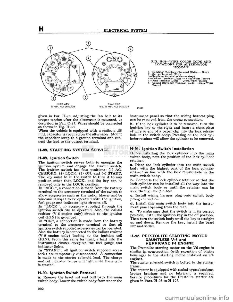
FIG.
H-38—WIRE
COLOR CODE
AND
LOCATIONS
FOR
ALTERNATOR HOOK-UP
1— Regulator (Auxiliary)
Terminal
(Cable —
Grey)
2— Output
Terminal:
(Red)
3—
Regulator
Terminal
(Cable —
Grey)
4—
Ground
Terminal
(Cable — Black-White
Tracer)
5—
Field
Terminal
(Cable — Green-White
Tracer)
6—
Ground
(Optional)
Terminal
(Cable — Black-White
Tracer)
REAR
VIEW
35
AMP.
ALTERNATOR
REAR
VIEW
40
& 55 AMP.
ALTERNATOR
given in Par. H-78, adjusting the fan belt to its
proper tension after the alternator is mounted, as described in Par. C-27. Wires should be connected
as shown in Fig. H-38.
When
the vehicle is equipped with a radio, a .55
mfd. capacitor is required on the alternator. Mount
the capacitor strap to a ground terminal and con
nect the lead to the output terminal.
H-88.
STARTING
SYSTEM
SERVICE
H-89.
Ignition
Switch
The
ignition switch serves both to energize the
ignition system and
engage
the starter switch.
The
ignition switch has four positions: (1) AC
CESSORY,
(2)
LOCK,
(3) ON, and (4)
START. The
key must be in the switch to turn it to any position other than
LOCK,
and the key can be
removed only in the
LOCK
position.
In "ACC",
a connection is made from the battery
terminal
to the accessory terminal of the switch to
allow accessories such as the radio, blower and/or
windshield wiper to be operated with the ignition, fuel
gauge
and indicator light circuits off.
In "LOCK",
no accessory supplied through the
ignition switch can be operated. Also, the ballast
resistor (V-6
engine
only) circuit to the ignition
coil
(IGN) is grounded.
In
"ON", a connection is made from the battery
terminal
to the accessory terminal so that all
ignition switch supplied accessories can be operated. Also the battery is connected to the ballast resistor
(V-6
engine
only) leading to the ignition coil
(IGN).
From
this same terminal, a lead
into
the
instrument cluster energizes the fuel
gauge
and
indicator lights.
In "START",
all ignition switch supplied acces
sories are temporarily disconnected. A connection is made to the starter solenoid lead. The charge
and
oil indicator lamps
will
light until the
engine
is started.
H-90.
Ignition
Switch
Removal
a.
Remove the bezel nut and pull back the main
switch body.
Lower
the switch
body
from under the instrument panel so that the wiring harness plug
can
be removed from the prong connection,
b. If the lock cylinder is to be removed, turn the
ignition key to the right and insert a short
piece
of wire or end of a paper clip
into
the lock release
hole
in the switch body. Pressing on the lock
cyl
inder retainer
will
allow the cylinder to be removed.
H-91.
Ignition
Switch
Installation
Before installing the lock cylinder
into
the main
switch body,
note
the position of the lock cylinder
retainer.
a.
Place the lock cylinder
into
the main switch
body
with the highest part of the lock cylinder
retainer in line with the lock release
hole
in the
main
switch body.
b. Compress the lock cylinder retainer so that the
lock cylinder can be installed all the way
into
the
main
switch
body
or until the retainer can be
seen
through the pin hole.
c.
Install
wiring harness plug
onto
switch
body
prong connection.
d.
Install
this main switch
body
into
the instru
ment panel opening from the
rear.
e. To make sure that the switch is in its correct position, install the ignition key in the off position.
Then
turn the switch
body
until the key is straight
up and down. Remove the key, install the bezel
nut and secure.
H-92.
PRESTOLITE
STARTING
MOTOR
DAUNTLESS
V-6 and
HURRICANE
F4
ENGINE
The
Prestolite starting motor on the V6
engine
is
similar
in construction (with exception of pinion housings) to the starting motor installed on F4
engines.
The
starter solenoid switch is bolted to the starter
frame.
The
starter is equipped with
sealed-type
absorbent
bronze bearings and no lubricant is required. Service procedures for the Prestolite starter are
given in
Pars.
H-93 to H-107. 202
Page 211 of 376
'Jeep'
UNIVERSAL
SERIES SERVICE
MANUAL
H
Note:
Pinion clearance cannot be adjusted. If
clearance is not correct, motor must be disassem
bled and checked for the above mentioned defects.
Any
defective parts must be replaced.
H-118. Starting Motor Test —
Genera!
To
obtain
full
performance data on a starting motor, or to determine the cause of abnormal
operation, the motor should be submitted to no-
load and locked armature
tests,
with equipment designed for such
tests.
A high-current variable resistance is required to obtain the specified volt
age at the starting motor.
This
is necessary since
a
small variation in the
voltage
will
produce a
marked
difference in the current
drawn.
H-119.
Starting Motor No-Load Test
This
test
requires a DC voltmeter capable of
read
ing
voltages
in a 12-volt
circuit,
a DC ammeter
with
maximum range of several hundred amperes,
a
high-current variable resistance, an rpm. in
dicator,
and a fully-charged, 12-volt battery.
a.
Connect a jumper lead
between
S terminal
and
large battery terminal of starter solenoid.
Con
nect voltmeter
between
either of
these
terminals (positive) and motor frame (negative, ground).
Connect
ammeter and variable resistance in series
between
positive terminal of battery and battery
terminal
of solenoid. Set up rpm. indicator to show starting motor speed.
b.
Initially,
adjust variable resistance to a value of
approximately .25 ohm. To complete the
circuit,
connect negative terminal of battery to motor
frame.
Adjust variable resistance to obtain a volt meter reading of 10.6 volts;
note
speed of starting motor and ammeter reading. Motor speed should
be
6750
to
10,500
rpm.; ammeter reading should
be 50 to 80 amperes.
c. Rated speed and current indicate normal condi
tion of the starting motor. Low speed and high
cur
rent
may show friction; this could be caused by
tight, dirty, or worn bearings, bent armature shaft,
or
a
loose
field
pole
shoe
dragging against the
armature.
It could also be caused by a short-cir cuited armature, or by grounded armature or field
coils.
d.
Failure
to operate and high current indicates
a
direct short circuit to ground at either the battery
terminal
or field coils.
e.
Failure
to operate and no current are usually
caused by broken brush springs, worn brushes, high insulation
between
commutator
bars,
or
some
other
condition preventing
good
contact
between
the brushes and commutator. It can also be caused by
open circuit in either the field coils or armature coils.
f. Low speed and low current show high resistance due to poor connections, defective leads, dirty com
mutator, or one of the conditions mentioned in e,
above.
g. High speed and high current indicates a short
circuit
in the field coils. H-120-
Locked
Armature Test
This
test
requires a DC voltmeter with range ap
propriate
to read
voltages
in a 12-volt
circuit,
a DC
ammeter with maximum range of several hundred
amperes, a high-current variable resistance, a
clamping fixture to lock
together
the motor shaft
and
case, and a fully-charged 12-volt battery.
a.
Connect a jumper lead
between
S terminal and
large battery terminal of starter solenoid. Connect
voltmeter
between
either of
these
terminals (posi
tive) and motor frame (negative, ground). Connect
ammeter and variable resistance in series
between
positive terminal of battery and battery terminal
of solenoid.
Install
clamping fixture to lock motor
shaft and case
together
securely.
b.
Initially,
adjust variable resistance to approxi
mately .05 ohm. To complete the
circuit,
connect
negative terminal of battery to motor frame. Ad
just
variable resistance to obtain a voltmeter
read
ing of 4.0 volts. Ammeter reading should be 280
to 320 amperes.
H-121.
Solenoid Starter Switch — Delco
The
solenoid-type switch is mounted directly on
the starting motor.
This
type of switch is energized
by turning the ignition key to the extreme right position. Should the solenoid switch
fail
in service
it
is necessary to install a new assembly.
Should
a starting motor
fail
to deliver maximum power the fault may be due to
voltage
drop at the
starter
switch contacts due to corrosion or burning.
Check
the switch by comparing the
voltage
at the
battery across the terminals. The
voltage
drop
should not exceed .05 volts per 100 amperes.
In
order to remove the starter solenoid, it is neces
sary
to remove the starter assembly.
H-122.
ELECTRICAL
INSTRUMENTS
H-123.
Fuel
Gauge —
CJ-3B
The
fuel
gauge
circuit is composed of the indicating
unit,
mounted on the instrument panel, and the
fuel tank unit, connected by a single wire through the ignition switch.
Should
the
gauge
fail
to register, check all wire con nections to be sure they are tight and clean; also
be sure both units are well grounded. If, after this
check, the
gauge
does
not indicate properly, remove
the wire from the tank unit and connect it to a
new tank unit which must be grounded to the tank
or
frame for
test.
Turn
the ignition switch "ON"
and
move
the float arm through its range of travel,
watching the dash unit to determine if it indicates
correctly.
If it fails to do so the trouble is probably
in
the dash unit and it should be replaced.
Should
a new tank unit be unavailable for this
test,
disconnect tank unit wire at the instrument panel
gauge.
Connect one lead of a 12 V, 1 CP
test
light
to the instrument panel unit terminal and with the
ignition switch
"ON"
ground the other lead. If the
unit is operating correctly the pointer
will
move
approximately three-quarter across the
dial.
Do not attempt to repair either unit; replacement
is the only precedure. 211
Page 212 of 376
H
ELECTRICAL
SYSTEM
H-124. Testing Indicators and Gauges
Two
gauges
(fuel and temperature) and two in dicators (oil pressure and battery charge) that are
located in the instrument cluster are electrically operated.
The
fuel
gauge
is connected by a single wire to a
float-and-slide-rheostat sending unit in the fuel
tank.
The
temperature
gauge
is connected by a single
wire
to a resistance-type sending unit mounted on the engine.
The
battery charge indicator operates when there
is a difference in potential
between
the generator
and
the battery
.The
battery charge indicator lights
when the generator is not charging the battery. The
indicator
light
goes
out when the generator
begins
to charge the battery.
The
oil pressure indicator is connected by a single
wire
to a diaphragm switch located on the engine.
When
engine
oil pressure is low or zero and the
ignition switch is on, the oil pressure indicator
will
light. When
engine
speed is increased slightly above idle speed, raising the oil pressure to approximately 6 psi. [0,2 kg-cm2], the diaphragm switch
will
open the circuit and the indicator light
will
go out.
A
voltage
regulator maintains a constant
voltage
to the
gauges
in normal operation. On early vehicles,
this
voltage
regulator was mounted on the
rear
of
the instrument cluster. On current vehicles, the
voltage
regulator is integral with the fuel
gauge.
Should
trouble
develop
in the
gauges,
first check the regulator (fuel
gauge
on current production vehicle). If the
voltage
to the regulator is below 10 volts system low
gauge
readings
will
result.
Voltage in
excess
of 16 volts
will
not affect
gauge
readings but may result in premature wear of the
regulator contacts. If the
voltage
to the regulator is
within
the above limits, check the electrical con nections to the regulator (or fuel gauge), especially
the ground connection. If the readings of all the
gauges
is too high, or they all read too low, replace
the regulator (or fuel gauge).
If
the temperature
gauge
or heat indicator in the
instrument cluster have failed, the cause may
originate from the jumper bar shorting out against the instrument case.
Check
the jumper bar
between
the temperature
gauge
and heat indicator at the
rear
of the instrument case. On later production vehicles, the jumper bar is covered with an in
sulating
sleeve
to protect it from shorting out
against the instrument case. If the jumper bar
does
not have this
sleeve,
either install one or
wrap
the bar with plastic electrical tape to
half
an
inch [12,7 mm.] from each end. When installing the jumper bar, be sure the curved
segment
is
closest to the fuel
gauge.
Should
only one of the two
gauges
register incor
rectly,
check the lead wire from the
gauge
to the
sending unit for shorts or open connections. Next disconnect the
gauge
from the sending unit, and
connect the
gauge
to a new fuel tank sending unit
which
has been grounded to the vehicle.
If
the
gauge
registers incorrectly when operating the new unit,
replace the
gauge;
if correctly, replace the sending
unit.
Should
a new fuel tank unit not be available for testing, use a 12-volt
test
light in its place. When
the
gauge
is operating correctly, the pointer
will
move
approximately three-quarters across the
dial.
On
some
vehicles, the temperature
gauge
may
register on or
close
to the H (hot)
mark
when
coolant temperature is
190°F.
to
200°F.
[88°C.
a
93°C.].
In such cases, a 25-ohm,
1-watt
resistor
may be installed on the temperature
gauge
which
will
place the pointer just beyond the center
mark
at a coolant temperature of
190°F.
to
200°F.
Install
the resistor
between
the two terminals on the back
of the
gauge.
Insulate the
exposed
leads of the resistor with electrical tape.
If
the oil pressure indicator
does
not indicate cor
rectly,
first check the light bulb. Next check all
connections and lead wires. If, after all possible
defects
are corrected, the indicator light
does
not go on and off properly, then the diaphragm type
switch in the cylinder block should be replaced.
H-12S.
LIGHTING SYSTEM The
wiring of the lighting systems is shown in
the wiring diagrams, which indicate the various units in relation to their positions in the vehicle.
The
wires in the various circuits are of different
colors or are marked by tracers to aid when check
ing individual circuits.
The
lighting circuits of all models are protected by
an
overload circuit breaker mounted on the back of the main light switch and no replaceable fuse is
required.
The
upper and lower headlight beams are con
trolled by a
foot
switch located on the toe board
to the left of the clutch pedal.
H-126.
Main
Light
Switch
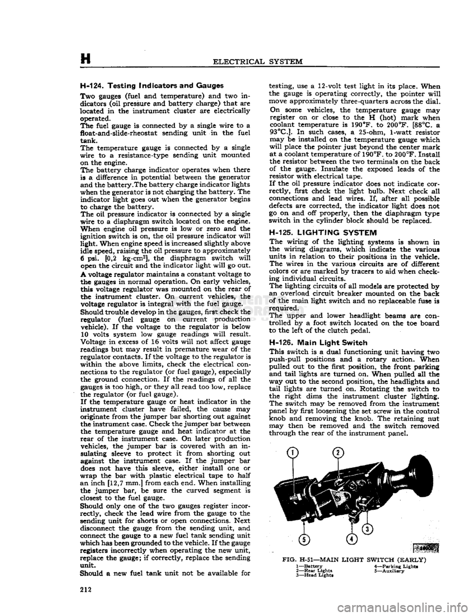
This
switch is a dual functioning unit having two
push-pull
positions and a rotary action. When
pulled out to the first position, the front parking
and
tail
lights are turned on. When pulled all the
way out to the second position, the headlights and
tail
lights are turned on. Rotating the switch to
the right dims the instrument cluster lighting.
The
switch may be removed from the instrument
panel by first loosening the set screw in the control
knob and removing the knob. The retaining nut may then be removed and the switch removed
through the
rear
of the instrument panel.
FIG.
H-51—MAIN
LIGHT
SWITCH
(EARLY)
1—
Battery
4—Parking Lights
2—
Rear
Lights 5—Auxiliary
3—
Head
Lights
212
Page 217 of 376
'Jeep'
UNIVERSAL
SERIES
SERVICE
MANUAL
H
cuit
lights,
the
signal switch
is
inoperative
and
must
be
replaced.
H-139.
Hazard
Warning Lights
All
current production vehicles
are
equipped with
a
four-way flasher warning system.
The
control switch
is
located
on the
instrument panel left
of
the steering column.
With
the
switch pulled
out,
the
two
front and
two
rear
turn
signal lights flash
on and
off
simultaneously,
as do
both
turn
signal
indicator
lights
on the
instrument clusters.
H-140.
Marker
Lights and Reflector Assembly
The
marker
lights
and
reflector assemblies
on
current
production vehicles
are
mounted
on the
side
of
the front fender and
on the
side
of
the
rear
quarter
panel.
The
spare wheel also mounts
a
marker
light. Some earlier production vehicles have
reflex reflectors mounted on the side of the hood and
on
the
side
of
the
rear
quarter panel. determine
if
dash wiper switch or wiring
is at
fault,
disconnect wiring harness from wiper motor
and
try
operating wiper independently
of
dash switch.
If
still
inoperative
see
procedure under
Par.
H-145.
b. Wiper
will
not
shut
off
— Determine
if
wiper
has both
low
and high speeds, slow speed only,
or
high speed only.
It is
important that
the
wiper
operates
at low
speed during parking cycle.
Dis
connect wiring harness from wiper motor
and try
operating wiper independently
of
dash switch.
If
wiper
shuts
off
correctly with
crank
arm
in
park
position and wiper has both speeds, check
the
lead
between
terminal
and
dash switch ground
and
check
for
defective dash switch.
If
wiper shuts
off
correctly,
but has
high speed only, check lead
be
tween wiper terminal and dash switch
for an
open
circuit
and check
for
defective dash switch.
If
still
inoperative,
see
Par. H-145.
c. Wiper
has
only fast speed.
Check
for
defective dash switch
or
open lead
between
terminal
and
dash switch.
H-141.
Windshield Wiper System
Early
production vehicles equipped with
the
Dauntless V-6
engine
have
two
single speed wind
shield wiper motors mounted above
the
windshield inside
the
vehicle. The wiper motors
are
operated
and
controlled
by a
switch located
on the
instru
ment panel.
Current
production vehicles with stationary wind
shield have
a
two-speed
electric windshield wiper motor mounted below
the
windshield outside
the
vehicle on the driver's side. The wiper motor switch is located
on the
instrument panel
to the
left
of
the steering column.
H-142.
Two-Speed Wiper Motor
The
two-speed
electric wiper motor
is
operated and
controlled
by a
turn
type, three poled, dash switch,
containing
a 6
amp. circuit breaker.
Current
flow
is directed from
the
battery through
the
ignition
switch
to the
wiper dash switch assembly
to the
two-speed
wiper motor, which passes current from the designated motor brush (high,
low or
park)
to
the armature circuit
to
ground.
H-143.
Troubleshooting Procedure
Troubleshooting procedures
are
divided into
two
categories: wiper troubleshooting
in
vehicle; wiper
troubleshooting
on
bench.
Fig. H-65 and H-66
illustrates connecting leads
of the
two-speed
wiper for either bench operation
or to run
wiper inde
pendently
of
dash switch and vehicle wiring when
installed
in the
vehicle.
H-144. Wiper Troubleshooting
in
Vehicle
Typical
wiper troubles and remedies are
as
follows
:
a.
Wiper
is
inoperative
—
Check
wiper switch
cir
cuit
breaker; wiring harness connection
at
wiper
motor
and
wiper switch; wiper motor
feed
wire
from
ignition starter switch
to
wiper switch;
and
check wiper
on
switch
to be
securely mounted.
With
ignition switch
on,
check
for 12
volts
at
har
ness
terminal that connects
to
wiper terminal.
To
BLACK
PARK
GREEN *-
RED m~
LOW
PARKING
<^^>
SWITCH
V^-O*'
HIGH
FIG.
H-64—WIRING
DIAGRAM
FIG.
H-65—WINDSHIELD
WIPER
SWITCH
ASSEMBLY
(EARLY)
1.
Park
(black)
2. Low (green)
3.
High (red)
d.
Wiper
has
only slow speed
and
shuts
off
with
dash switch in high speed position. Reverse harness
leads that connect
to
wiper terminals.
e. If
blades
do not
return
to
park
position when
wiper
is
turned
off,
check wiper ground connection
to vehicle body. Remove wiper from vehicle
and
check
for
dirty, bent,
or
broken
park
switch con
tacts.
f.
If
wiper speed
is
normal
in
slow,
but too ex
cessive
in
fast speed, check for an open terminal. 217
Page 314 of 376
STEERING
SYSTEM
O-L
GENERAL
The
steering system on all Jeep Universal vehicles
consists of the steering gear, steering wheel, steering column and shaft, and steering linkage.
This
section covers wheel alignment, steering linkage,
steering gear, steering column and steering wheel.
0-2. Steering
Gear
Function
The
steering gear is a reducing gear. It exchanges a
relatively
large amount of movement with a small force (applied by the driver at the steering wheel), for a much smaller amount of movement with a
greatly increased force through a cam and lever
action type steering gear. The steering gear ratio is 17.9 to 1 on vehicles equipped with the F4
engine
and
19 to 1 with the V6 engine.
0-3. Steering
Linkage
Refer
to Fig. O-l.
The
steering linkage consists of a steering arm at
tached to the steering gear, a steering connecting
rod,
(drag
link),
connecting the steering arm to the
beilcrank,
and a steering tie rod connecting the
beilcrank
to the axle tie rod. The beilcrank pivots
on a pin mounted just to the left of the frame front crossmember. The steering tie rod is connected to
the beilcrank and
extends
to the right
ball
joint as sembly of tie rod. The tie rod
extends
to the wheels,
being connected to their respective steering knuckle
arms
at the wheels.
With
this linkage arrangement,
as the steering arm
moves
rearward,
the front
wheels
turn
to the left. As the steering arm
moves
forward,
the wheels
turn
to the right.
Ball
joints are used to secure the drag
link,
steering
connecting rod and tie rod ends. The
ball
joints
assist in maintaining
good
steering control and con
stant toe-in of the front wheels under all driving conditions. If the
ball
joints
become
worn enough
to allow free motion in the linkage, they should be,
replaced.
Note:
Ball
joint replacement of the tie rod requires
resetting of the wheel toe-in adjustment.
0-4.
Steering
Column
and Gear
Alignment
When
adjusting a steering gear remove all loads
from
the unit by disconnecting the steering con
necting rod (drag
link)
from the steering arm and
also
loosen
the instrument panel bracket and the
steering gear to frame
bolts
to allow the steering
post
to correctly align itself. When retightening the
steering gear to frame
bolts
use a torque wrench
pull
of 45 to 55 lb-ft. [6,2 a 7,6 kg-m.] on the
Vk*
bolts
and 30 to 40 lb-ft. [4,15 a 5,5 kg-m.] on the
Vs"
bolts. 10811
FIG.
0-2—STEERING
GEAR
1—Nut
2
—Lockwasher
3—
Steering
Gear
Arm 4—
Lever
Shaft Oil Seal
5—
Outer
Housing Bushing
6—
Inner
Housing Bushing 7—
Filler
Plug
8—
Cover
and Tube
9—
Ball
Retaining
Ring
10—Cup
11—
Ball
(Steel)
12—
Tube
and Cam
13—
Shims
14—
Upper
Cover
15—
Lockwasher
16—
Bolt
17—
Steering
Wheel 18—
Horn
Button Retainer
19—
Horn
Button
20—
Horn
Button Cap 21— Nut
22—
Spring
23—
Spring
Seat
24—
Bearing
25—
Horn
Cable
26—
Horn
Button Spring
27—
Spring
Cup
28—
Steering Column
29—
Oil
Hole
Cover
30—
Clamp
31—
Adjusting
Screw
32— Nut
33—
Bolt
34—
Side
Cover
35—
Gasket
36—
Shaft
and
Lever
37—
Housing
314