run flat JEEP CJ 1953 Service Manual
[x] Cancel search | Manufacturer: JEEP, Model Year: 1953, Model line: CJ, Model: JEEP CJ 1953Pages: 376, PDF Size: 19.96 MB
Page 51 of 376
![JEEP CJ 1953 Service Manual
-Jeep*
UNIVERSAL
SERIES SERVICE
MANUAL
E>
[5,928 a
5,926
cm.] for all main bearings. Allowable
taper or out-of-round of the journals is .001"
[0,0254
mm.].
D-42.
Checking Connecting Ro JEEP CJ 1953 Service Manual
-Jeep*
UNIVERSAL
SERIES SERVICE
MANUAL
E>
[5,928 a
5,926
cm.] for all main bearings. Allowable
taper or out-of-round of the journals is .001"
[0,0254
mm.].
D-42.
Checking Connecting Ro](/img/16/57040/w960_57040-50.png)
-Jeep*
UNIVERSAL
SERIES SERVICE
MANUAL
E>
[5,928 a
5,926
cm.] for all main bearings. Allowable
taper or out-of-round of the journals is .001"
[0,0254
mm.].
D-42.
Checking Connecting Rod
Crankpins
Check
the crankpin diameters with a micrometer
to ensure that they are not out-of-round or tapered more than .001"
[0,0254
mm.] The standard
crank-
pin
diameter is
1.9383*
to
1.9375"
[4,9233
a
4,9213
cm.].
D-43.
Crankshaft
Main
Bearings
The
crankshaft rotates on three main bearings
with
a running clearance of .0003" to .0029"
[0,0076
a
0,0736
mm.].
These
bearings are positioned and prevented from
rotating in their supports in the cylinder block by
dowel pins. Dowel pins are used in both the center
and
the
rear
bearing caps. No dowel pins are used
in
the front bearing cap because the bearing has
a
flange. The front main bearing takes the end
thrust
of the crankshaft. The main bearings are of premium type which provides long bearing life.
They
are replaceable and when correctly installed, provide proper clearance without filing, boring,
scraping,
or shimming. Crankshaft bearings can
be removed from this
engine
only with the
engine
out of the vehicle. Crankshaft bearings must be replaced as a complete set of three bearings, each
bearing consisting of two halves.
Main
bearings
are
available in the standard size and the following
undersizes:
.001" [0,025mm.] .012" [0,305 mm.] .002" [0,051mm.] .020" [0,508 mm.] .010" [0,254mm.] .030" [0,762 mm.]
The
.001" and .002" undersize main bearings are
for use with standard size crankshafts having
slightly worn
journals.
The .010", .020", and .030" undersize bearings are for use with undersize
crankshafts
in
those
sizes. The .012" undersize
bearings are for use with .010" undersize
crank
shafts having slightly worn journals. Bearing sizes
are
rubber stamped on the reverse side of each
bearing half.
D-44. Crankshaft
Main
Bearing Inspection
The
crankshaft
journals
must be carefully inspected
as detailed previously in Par. D-41. Worn journals
will
require undersize bearings. Scored, flaked, or
worn
bearings must be replaced. Measure the main
bearing bores in the cylinder block using a
telescope
gauge
and micrometer. Measure the bores at right
angles to the split line and at 45° to the split line.
The
bores should not be over .001"
[0,0254
mm.]
out-of-round or .001" in taper from end to end.
Also,
the bores should not be more then .001"
oversize, considering the average diameter of the
bore.
D-45.
Fitting Crankshaft
Main
Bearings
Using
Plastigage
After
wiping and carefully inspecting the bearing bore, install the proper bearing. See that the oil
hole
in the bearing upper half registers properly
with
the oil
hole
in the block, and that the bearing
lock fits properly in the notch in the block.
Install
the crankshaft if replacing bearings with the
engine
out of the vehicle. The desired running fit (dif
ference
between
the diameter of the crankshaft
journal
and the inside diameter of the fitted bear ing) for a main bearing is .0003" to .0029"
[0,0076
a
0,0736
mm.]. With a dimension in
excess
of this
standard
running fit, a satisfactory bearing replacement cannot be made and it
will
be necessary to
regrind
the crankshaft.
Install
the bearing lower
half
and the bearing cap and draw the nuts down
equally and only slightly tight. Rotate the
crank
shaft by hand to be sure it turns freely without
drag.
Pull
the nuts tighter, first one then the other,
a
little at a time, intermittently rotating the
crank
shaft by hand until the recommended torque of
35 to 45 lb-ft. [4,8 a 6,2 kg-m.] is reached. If the
bearings are of the correct size, and lubricated with
light oil before installation, the crankshaft should
turn
freely in the bearings. If the crankshaft cannot
be turned, a larger bearing is
required.
If there is no binding or tightness, it is still necessary to check
clearance to guard against too
loose
a fit. Never file
either the bearing cap or the bearing to compensate
for too much clearance. Do not use shims under a
bearing cap or behind a bearing shell. Do not run a
new bearing half with a worn bearing half. The use
of "Plastigage" of the proper size to measure .001" [0,025 mm.] clearance is recommended for check
ing crankshaft main bearing clearance. The method
of checking clearance is as follows:
a.
Remove the bearing cap and carefully wipe
all
oil from the bearing and the
journal.
b.
Lay a piece of "Plastigage" y%" [3 mm.]
shorter than the width of the bearing across the
journal
(lengthwise of the crankshaft).
c.
Install
the bearing and cap and tighten first
one nut, then the other, a little at a time to the specified torque. As the bearing
tightens
down
around
the
journal,
the "Plastigage" flattens to a
width that indicates the bearing clearance.
d.
Remove the cap and measure the width of
the flattened "Plastigage," using the scale printed
on the
edge
of the envelope. The proper size "Plasti
gage"
will
accurately measure clearance down to .001".
e. If the flattened "Plastigage" tapers toward the middle, or toward the end, or both ends, there
is a difference in clearance, indicating a taper, a
low
spot,
or other irregularity of the bearing or
journal.
D-46.
Fitting Crankshaft
Main
Bearings
Using
Shim Stock
Thin
feeler or shim stock may be used instead of "Plastigage" to check bearing clearances. The
method is simple, but care must be taken to protect
the bearing metal surface from
injury
by too much pressure against the feeler stock,
a.
Cut a piece of .001" [0,025 mm.] thick, by Yl [12,7 mm.] wide, feeler stock }4" [3 mm.]
shorter than the width of the bearing. Coat this 51
Page 57 of 376
'Jeep5
UNIVERSAL SERIES SERVICE
MANUAL
D
Driver
W-238 is equipped
with
an
adapter
ring
which
correctly positions the guides. See Fig. D-23. Start a new exhaust valve guide, blunt (nontapered)
end
first,
into
the valve guide bore in the top of the cylinder block. When properly positioned, the
top end of the guide is exactly
1
"
[25,4 mm.] below
the level of the top of the block as shown in Fig.
D-24.
Start
a new intake valve guide, tapered end
first, into position from the
bottom
of the cylinder
head.
When properly positioned, the end of the
guide is just flush with the end of the valve guide
bore in the cylinder head as shown in Fig. D-24.
Run
a reamer (Tool
C-3 8)
through the new
guides
after they have been correctly positioned.
D-62. Tappets
and
Cover
The
valve tappets are lubricated through oil troughs cast in the crankcase. The troughs are
filled by oil sprayed from the connecting rod ends
and
passages are drilled through the tappet
guides
to
carry
the oil to the tappets. A
groove
around the center of the tappet shank carries the oil up and down the guide.
Check
the threads and fit of the exhaust valve ad
justing
screw in the exhaust valve tappets. The fit of a screw should be such that a wrench is required to
turn
it into or out of the tappet as
these
are of
the self-locking type. Replace the worn part, either
the screw or the tappet, or both, if there is
loose
ness
between
the parts.
D-63.
Crankshaft Rear Bearing Seal
Oil
leakage through the
rear
main bearing is pre vented by a metal supported neoprene lip type
seal
which can readily be installed without remov
ing the crankshaft.
Should
trouble be experienced with oil leaking
from
the
rear
main bearing there are several points
which
should be checked.
a.
Be sure that the identifying paint daub on the
bearing
cap is the same as that appearing on the
center bearing web.
b.
The bearing to crankshaft clearance must not
exceed .0029"
[0,0736
mm.].
c.
Place sealer on the faces of the
rear
bearing cap
from
the
rear
oil
groove
to the oil seal grooves.
d-
Be sure the rubber oil seals extend about 34" [6 mm.] below the
bottom
face of the cap.
e.
Be sure the oil pan gasket is not leaking.
f.
Check
to be sure the oil leak is not at the cam
shaft
rear
bearing expansion plug or from the
crankcase.
D-64.
Floating Oil
Intake •
Refer to Fig. D-25 and D-26.
The
floating oil intake is attached to the
bottom
of the crankcase with two screws. The float and
screen causes it to ride, raise and lower with the
amount of oil in the pan.
This
prevents water or
dirt,
which
may have accumulated in the
bottom
of the oil pan, from circulating through the
engine
because the oil is drawn horizontally from the top
surface.
Whenever removed, the float, screen, and
tube should be cleaned thoroughly to remove any
accumulation
of
dirt.
Also clean the oil pan.
Fluctuating
oil pressure can usually be traced to
an
air leak
between
the oil float support and the
crankcase.
Be
sure the float support flange is flat.
Clean
both
the flange and the crankcase surfaces thoroughly
before installing a new gasket. Be sure the retaining
screws are tight.
D-65. Oil
Pump
The
oil pump is located externally on the left side
of the engine. In operation oil is drawn from the
crankcase
through the floating oil intake then passes through a drilled passage in the crankcase
to the pump from which it is forced through
drilled
passages to the crankshaft and camshaft
bearings. When it is necessary to remove an oil
pump,
first remove the distributor cover and
note
the position of the distributor rotor so that the pump may be reinstalled without disturbing the
ignition timing. To install the pump without dis
turbing
the timing, the pump gear must be cor
rectly
meshed with the camshaft driving gear to
allow
engagement
of the key on the distributor shaft with the pump shaft slot, without changing the position of the distributor rotor. Distributor
can
be installed only in one position as the slot and
driving
key are machined off-center.
The
oil pump consists of an inner and outer rotor
within
the pump body. An oil relief valve is mounted in the pump body which controls the oil
pressure.
To disassemble the pump, Fig. D-27, first remove the gear which is retained by straight
pin.
It
will
be necessary to file off one end of the
pin
before driving it out with a small drift. By re
moving the cover the outer rotor and the inner
rotor
and shaft may be removed through the cover opening.
Failure
of the pump to operate at
full
efficiency may usually be traced to excessive
end float of the rotors or excessive clearance be tween the rotors. The clearance
between
the outer
rotor
and the pump body should also be checked.
Match
the rotors
together
with one
lobe
of the inner
rotor
pushed as far as possible into the notch of the outer rotor. Measure the clearance
between
the
lobes
of the rotors as shown in
Fig.
D-28.
This
clear ance should be .010"
[0,254
mm.] or less.
If
more, replace both rotors. Measure the clearance
between
the outer rotor and the pump body as
shown in Fig. D-29. Should this clearance exceed .012" [0,305 mm.] the fault is probably in the
pump body and it should be replaced. End float
of the rotors is controlled by the thickness of the cover gasket which is made of special material that
can
be only slightly compressed. Never use other
than
a standard factory gasket.
Check
the cover
to be sure the inner surface is not rough or scored
and
that it is flat within .001" [0,025 mm.]
tested
with
feeler
gauges,
Fig. D-30. Measure thickness of
the rotors which must be within .001" [0,025 mm.]
of each other. Assemble the rotors in the pump body and install the cover without the gasket.
When
the cover screws are tightened to normal
tension, there should be interference
between
the
rotors and the cover making it impossible to
turn
the pump shaft by hand. Remove the cover and re- 57
Page 116 of 376
E
FUEL
SYSTEM
pressing downward on metering rod) or
seats
be
fore the metering rod arm makes flat contact with the pump lifter link, make adjustment by bending
the lip on the metering rod arm.
E-17.
Choke System
The
choke system consists of a manually-operated
choke valve, a fast-idle connecting rod, and a fast-
idle arm. The choke valve is offset-spring loaded to prevent over-choking during the starting warm-
up period. When the choke valve is moved to a closed position for starting, the fast idle connector
rod
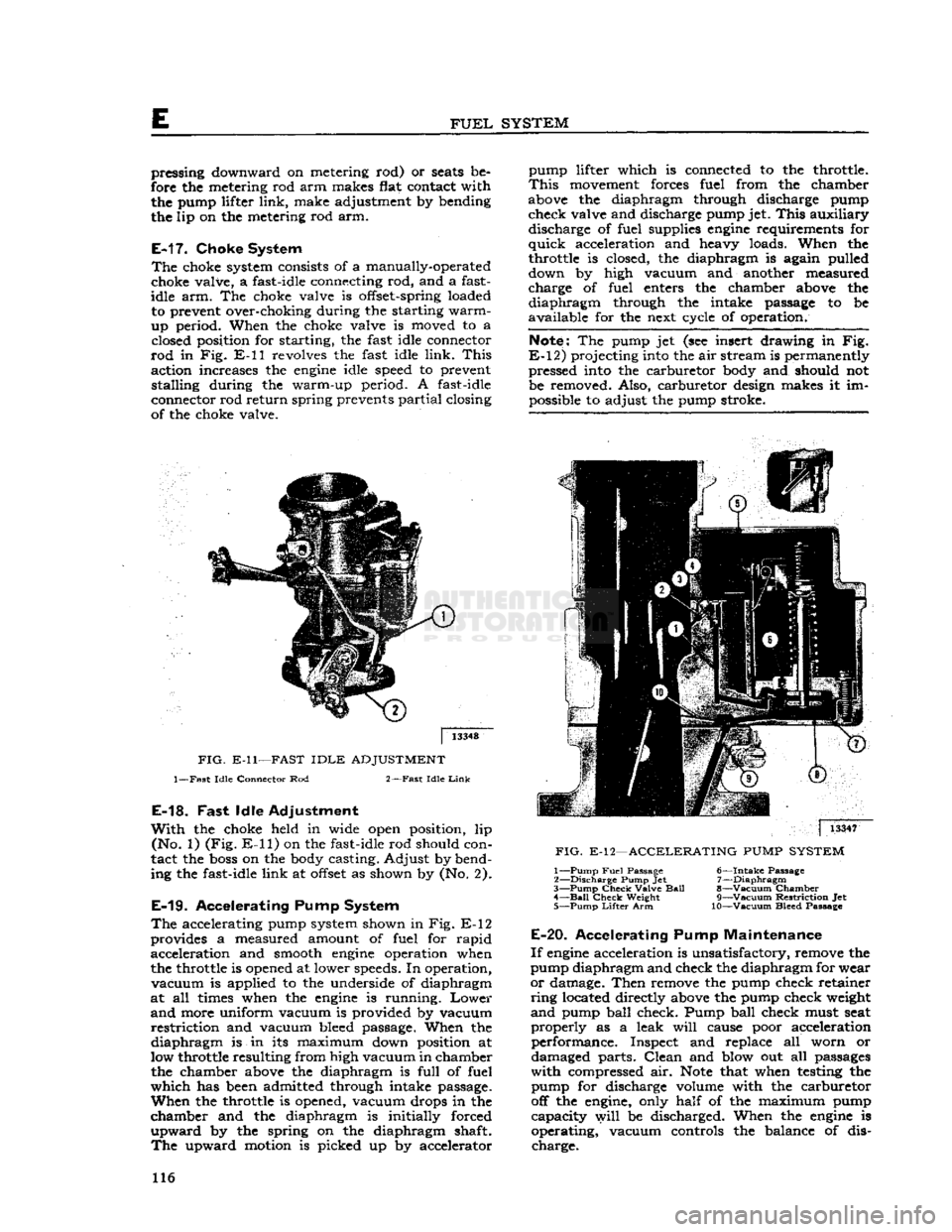
in Fig. E-ll revolves the fast idle link.
This
action increases the
engine
idle speed to prevent stalling during the warm-up period. A fast-idle
connector rod return spring prevents partial closing
of the choke valve. pump lifter which is connected to the throttle.
This
movement forces fuel from the chamber
above the diaphragm through discharge pump check valve and discharge pump jet.
This
auxiliary discharge of fuel supplies
engine
requirements for
quick
acceleration and heavy loads. When the
throttle is closed, the diaphragm is again pulled
down by high vacuum and another measured
charge of fuel enters the chamber above the
diaphragm
through the intake passage to be
available for the next cycle of operation.
Note:
The pump jet (see insert drawing in Fig.
E-12)
projecting into the air stream is permanently pressed into the carburetor body and should not
be removed. Also, carburetor design makes it im possible to adjust the pump stroke.
FIG.
E-ll—FAST
IDLE
ADJUSTMENT
1—Fast
Idle
Connector Rod
2—Fast
Idle
Link
E-18.
Fast
Idle Adjustment
With
the choke held in wide open position, lip (No. 1) (Fig.
E-ll)
on the fast-idle rod should con
tact the
boss
on the body casting. Adjust by bend
ing the fast-idle link at
offset
as shown by (No. 2).
E-19.
Accelerating Pump System
The
accelerating pump system shown in Fig. E-12
provides a measured amount of fuel for rapid acceleration and smooth
engine
operation when
the throttle is opened at lower speeds. In operation,
vacuum
is applied to the underside of diaphragm
at all times when the
engine
is running.
Lower
and
more uniform vacuum is provided by vacuum
restriction
and vacuum bleed passage. When the
diaphragm
is in its maximum down position at
low throttle resulting from high vacuum in chamber the chamber above the diaphragm is full of fuel
which
has been admitted through intake passage.
When
the throttle is opened, vacuum drops in the
chamber and the diaphragm is initially forced
upward
by the spring on the diaphragm shaft.
The
upward motion is picked up by accelerator
|
13347
FIG.
E-12—ACCELERATING
PUMP
SYSTEM
1—
Pump
Fuel
Passage
6—Intake
Passage
2—
Discharge
Pump Jet 7—Diaphragm
3—
Pump
Check
Valve
Ball
8—Vacuum Chamber 4—
Bail
Check
Weight
9—Vacuum
Restriction
Jet
5—
Pump
Lifter
Arm 10—Vacuum Bleed Passage
E-20.
Accelerating Pump Maintenance
If
engine
acceleration is unsatisfactory, remove the
pump diaphragm and check the diaphragm for wear
or
damage. Then remove the pump check retainer
ring
located directly above the pump check weight
and
pump ball check. Pump ball check must seat
properly
as a leak
will
cause poor acceleration performance. Inspect and replace all worn or
damaged parts.
Clean
and blow out all passages
with
compressed air.
Note
that when testing the pump for discharge volume with the carburetor
off the engine, only half of the maximum pump capacity
will
be discharged. When the
engine
is
operating, vacuum controls the balance of dis charge. 116
Page 118 of 376
E
FUEL
SYSTEM
Note:
Do not remove pressed-in parts such as
nozzle, pump jet, or antipercolator air bleed.
j.
Remove body flange attaching screws, body flange assembly, and gasket.
k.
Remove idle-adjustment screw, spring, idle
port
rivet, throttle lever assembly, washer, fast
idle arm, throttle plate screws, throttle plate, and throttle shaft.
1. Remove throttle shaft seal by prying out seal
retainer.
Note:
Do not remove pressed-in vacuum passage
orifice.
m.
Remove choke valve screws and choke valve.
Unhook
choke spring and slide shaft from housing,
n.
Wash all parts in carburetor cleaning solution
and
blow out passages with compressed air. Do not immerse diaphragm or seals in cleaning solution.
Inspect
all parts for wear or damage. Always use
new gaskets when reassembling.
E-22.
Carburetor
Reassembly
•
Refer to Fig. E-13.
To
expedite
reassembly, it is advisable to group all
related
parts by the circuit to which they belong.
a.
Install
throttle shaft seal and retainer in flange casting.
b.
Install
fast-idle
arm,
washer, and lever assembly
on throttle shaft. Slide shaft into place and install throttle valve.
c.
Install
idle port rivet plug and idle adjusting
screw
and spring.
d.
Attach flange assembly to body casting. Use new gasket.
e.
Install
low-speed jet assembly.
f.
Early
production models install pump intake
strainer
in pump diaphragm housing and carefully
press into recess.
Note:
If strainer is even slightly damaged, a new
one must be installed.
g.
Install
pump diaphragm assembly in diaphragm housing.
Then,
install pump diaphragm spring
(lower)
and retainer.
h.
Install
pump lifter
link,
metering rod
arm,
upper
pump spring, and retainer.
I.
Install
metering rod jet.
Note:
No gasket is used with this jet.
j.
Install
diaphragm housing attaching screws in
the diaphragm housing, making sure that the
edges
of the diaphragm are not wrinkled.
Lower
into place and tighten screws evenly and securely,
k.
Install
throttle shaft seal, dust seal washer, and
shaft seal spring.
I.
Install
pump connector
link
in the throttle arm
assembly.
Install
throttle shaft arm assembly on
throttle shaft guiding connector
link
in pump lifter
link
hole.
CAUTION:
Linkage
must not bind in any throttle
position. If binding occurs,
loosen
clamp screw in
throttle arm, adjust slightly, then retighten screw.
m.
Install
pump check disc, disc retainer, and lock
ring.
n.
Install
metering rod and pin spring. Connect
metering rod spring.
o.
Check
and if necessary correct meter ing rod adjustment. Follow procedure of
Par.
E-16.
p.
Install
needle
seat and gasket assembly, needle,
float
and
float pin. The
stop
shoulder on the float
pin
must be on the side away from the bore of
the carburetor.
q.
Set float level to specifications. Follow pro cedure of
Par.
E-12.
r.
Install
air horn gasket and air horn assembly.
Install
attaching screws, lock washers, and choke
tube clamp assembly. Tighten center screws first,
s. Slide choke shaft and lever assembly into place
and
connect choke lever
spring.
Install
choke valve.
Center
the valve by tapping lightly, then hold in
place with fingers when tightening screws,
t.
Install
fast-idle connector rod with
offset
portion
of rod on top and pin spring on outside.
Install
fast-idle connecting rod spring.
E-23.
Correcting Acceleration
Flat
Spot
Early
production
Carburetor
Models 938-S, 938-
SA,
938-SC
Inasmuch
as a flat
spot
on acceleration or low speed
stumble can
come
from causes other than
car
buretor
malfunction, it is recommended that
engine
tuning be thoroughly checked before attempting
any
actual carburetor work. Make sure that
ignition, compression, and timing are correct and
that fuel pump is supplying enough gas. Also, the F-head
engine
employs a water-heated intake
manifold.
Proper vaporization of the fuel depends
on correct intake manifold temperature. Since this
temperature is controlled by the cooling system
thermostat, include an operational check of the
thermostat when diagnosing the stumble. Operating
temperatures consistently below
155°F.
can cause stumble.
If
the stumble persists, a
YF-938-S,
YF-938-SA,
or
YF-938-SC
carburetor can be converted to a
YF-938-SD
carburetor by installing Special Kit
924161, consisting of a pump discharge check
needle, a metering rod, and a metering rod jet. If this kit is installed, the pump discharge check
needle
replaces the original
ball,
weight, and re
tainer
and the small wire-type retainer used with
the
ball
check assembly must not be reinstalled.
When
installing the kit, check the size of the pump discharge jet, No. 2, Fig. E-14.
Early
production
YF-938S
and
YF-938SA
carburetors have a .025" [0,635 mm.] jet installed. If the carburetor being
converted has a .025" jet it must be opened up to .031" [0,787 mm.] by running a No. 68
drill
through
the jet as shown in
Fig.
E-14.
The jet must be drilled
as it is a pressed in part and cannot be replaced.
Upon
completing the installation of the conversion
kit,
mark
or tag the carburetor to indicate that it
is a
YF-938SD.
118
Page 126 of 376
FUEL
SYSTEM
|
11893
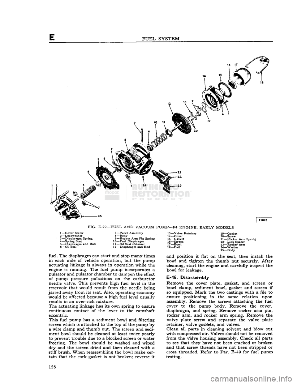
FIG.
E-29—FUEL
AND
VACUUM
PUMP—F4
ENGINE,
EARLY
MODELS
1—
Cover
Screw
2—
Lockwasher
3—
Diaphragm
Spring
4—
Spring
Seat 5—
Diaphragm
and Rod
6—
Oil
Seal 7—
Valve
Assembly
8— Body
9—
Rocker
Arm Pin Spring
10—
Fuel
Diaphragm
11—
Oil
Seal Retainer
12—
Diaphragm
and Rod 13—
Valve
Retainer
14—
Cover
15—
Gasket
16—
Screen
17—
Bow!
18—
Bail
19—
Gasket
20—
Screw
21—
Rocker
Arm Spring
22—
Link
Spacer
23—
Rocker
Arm
24—
Washer
25—
Body
fuel. The diaphragm can start and
stop
many
times
in
each mile of vehicle operation, but the pump
actuating lihkage is always in operation while the
engine
is running. The fuel pump incorporates a
pulsator and pulsator chamber to dampen the
effect
of pump pressure pulsations on the carburetor
needle
valve.
This
prevents high fuel level in the
reservoir
that would result from the
needle
being
jarred
away from its seat. Also, operating
economy
would be affected because a high fuel level usually results in an over-rich mixture.
The
actuating linkage has its own spring to ensure
continuous contact of the lever to the camshaft
eccentric.
This
fuel pump has a sediment bowl and filtering
screen which is attached to the top of the pump by
a
wire clamp and thumb nut. The screen and sedi
ment bowl should be cleaned at least twice yearly
to prevent trouble due to a blocked screen or water
freezing. The bowl should be washed and wiped
dry
and the screen dried and then cleaned with a
stiff
brush.
When reassembling the bowl make cer
tain
that the cork gasket is not broken; reverse it
and
position it flat on the seat, then install the
bowl and tighten the thumb nut securely. After
cleaning, start the
engine
and carefully inspect the
bowl for leakage.
E-46.
Disassembly
Remove the cover plate, gasket, and screen or
bowl clamp, sediment bowl, gasket and screen if so equipped.
Mark
the two castings with a file to
ensure positioning in the same relation upon
assembly. Remove the screws attaching the fuel cover to the pump body. Remove the cover,
diaphragm,
and spring. Remove rocker arm pin,
rocker
arm, and rocker arm spring. Remove the
valve plate screw and separate the valve plate
retainer,
valve gaskets, and valves.
Clean
all parts in cleaning solvent and blow out
with
compressed air. Valves should not be removed
from
the valve housing assembly.
Check
all parts
to see that
they
have not
been
cracked or broken
and
that screw threads have not
been
stripped or
cross threaded. Refer to Par. E-49 for fuel pump
testing. 126
Page 165 of 376
'Jeep*
UNIVERSAL SERIES SERVICE
MANUAL
G
FIG.
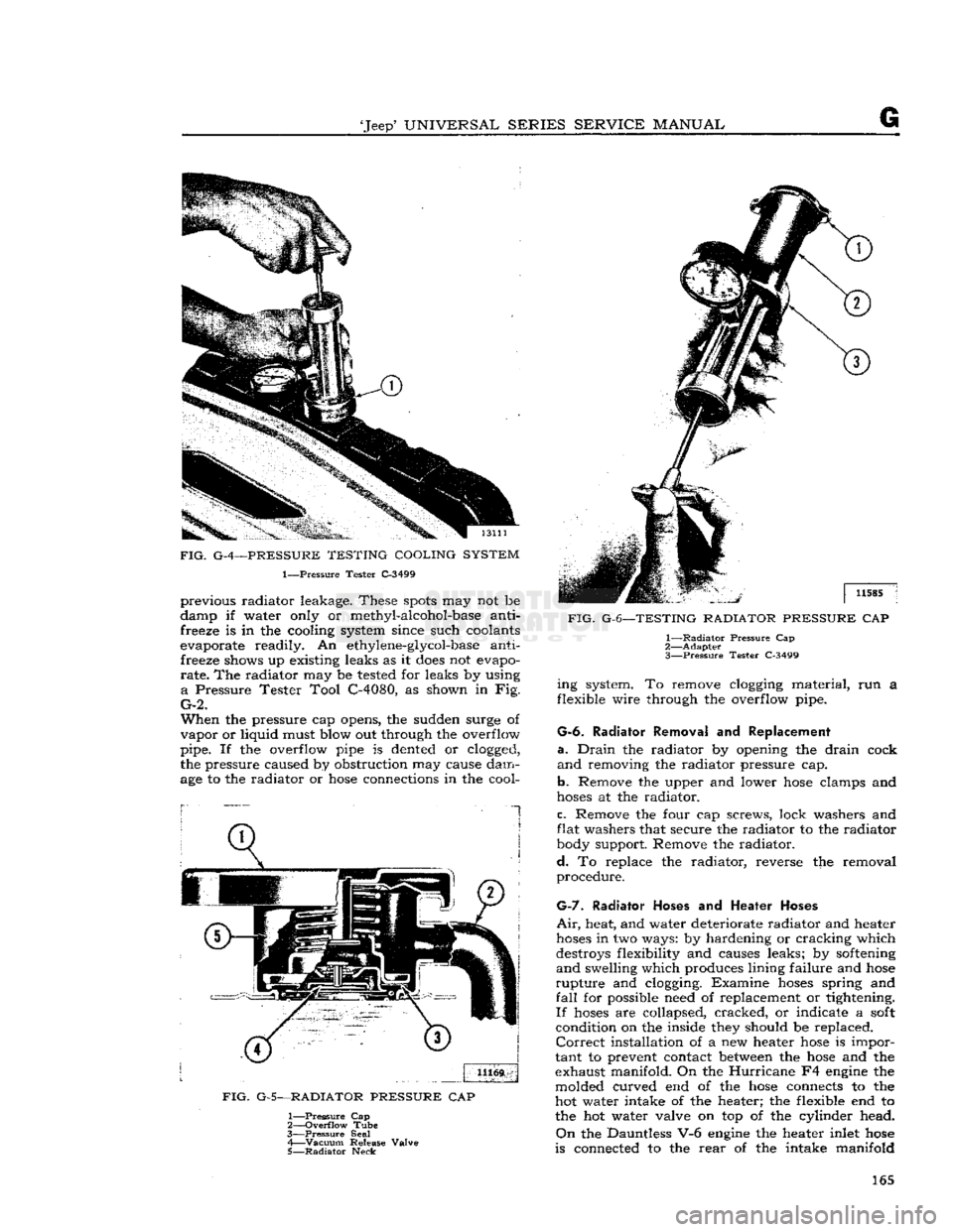
G-4—PRESSURE TESTING COOLING SYSTEM
1—Pressure Tester C-3499 previous radiator leakage. These
spots
may not be
damp if water only or methyl-alcohol-base anti freeze is in the cooling system since such coolants
evaporate readily. An ethylene-glycol-base anti freeze shows up existing leaks as it
does
not evapo
rate.
The radiator may be tested for leaks by using
a
Pressure Tester Tool C-4080, as shown in Fig.
G-2.
When
the pressure cap opens, the sudden surge of
vapor
or liquid must blow out through the overflow
pipe. If the overflow pipe is dented or clogged,
the pressure caused by obstruction may cause dam
age to the radiator or
hose
connections in the cool-
1
FIG.
G-5—RADIATOR PRESSURE
CAP
1—
Pressure
Cap
2—
Overflow
Tube
3—
Pressure
Seal 4—
Vacuum
Release Valve
5—
Radiator
Neck
FIG.
G-6—TESTING RADIATOR PRESSURE
CAP
1—
Radiator
Pressure Cap
2—
Adapter
3—
Pressure
Tester C-3499 ing system. To remove clogging material, run a
flexible wire through the overflow pipe.
G-6.
Radiator Removal
and
Replacement
a.
Drain
the radiator by opening the
drain
cock
and
removing the radiator pressure cap.
b.
Remove the upper and lower
hose
clamps and
hoses
at the radiator.
c.
Remove the four cap screws, lock washers and
flat washers that secure the radiator to the radiator
body support. Remove the radiator.
d.
To replace the radiator, reverse the removal
procedure.
G-7.
Radiator
Hoses
and
Heater Hoses
Air,
heat, and water deteriorate radiator and heater
hoses
in two ways: by hardening or cracking which
destroys flexibility and causes leaks; by softening
and
swelling which produces lining failure and
hose
rupture
and clogging. Examine
hoses
spring and
fall
for possible need of replacement or tightening.
If
hoses
are collapsed, cracked, or indicate a
soft
condition on the inside they should be replaced.
Correct
installation of a new heater
hose
is impor
tant to prevent contact between the
hose
and the
exhaust manifold. On the
Hurricane
F4 engine the
molded curved end of the
hose
connects to the
hot water intake of the heater; the flexible end to the hot water valve on top of the cylinder head.
On
the Dauntless V-6 engine the heater inlet
hose
is connected to the
rear
of the intake manifold 165
Page 192 of 376
H
ELECTRICAL
SYSTEM
Regulator
ground screw to battery ground post
—.03-volt maximum.
Generator
frame to battery ground post—.03-volt
maximum.
H-47.
Test Procedure
a.
Circuit
Breaker—Connect
an ammeter in series between the regulator B-terminal and the lead
wire
removed from that terminal. Connect a
voltmeter between the regulator
A-terminal
and the regulator mounting base. Disconnect the field lead
from
the regulator
F-terminal
and insert a variable resistance (3 amp., 50 ohm capacity) between the
lead
and the regulator terminal. Run the generator
at about 1000 generator rpm. Insert all the re
sistance in the field
circuit,
then slowly reduce the
resistance noting the voltage reading just before the change caused by the closing of the circuit
breaker.
Increase the charging rate to the figure
specified for the regulator being tested then reduce
the charging rate by inserting resistance in the
field
circuit.
Note
the voltmeter and ammeter
reading
just before the circuit breaker
opens
and
the ammeter reading drops to zero. The closing voltage and the opening voltage or current should
be within the limits specified. An accurate method
for noting the exact instant of the opening or closing
of the circuit breaker is to connect a headphone (2000 ohms or higher) to the battery and armature
terminals
of the regulator. When the contacts
open or close a
click
will
be
heard
in the headphones.
To
adjust the closing voltage change the armature
spring
tension by bending the hanger at the lower end of the spring. Increase the spring tension to
raise
the closing voltage or decrease the tension
to lower the closing voltage. To adjust the opening voltage raise or lower the stationary contact
keeping the contacts perfectly aligned. Increasing
the contact gap lowers the opening
'
voltage.
Change
the contact gap by expanding or contract
ing the stationary contact bracket, keeping the
contacts aligned. Do not adjust the gap between
the contacts to less than the specified minimum.
b.
Voltage Regulator—Connect the ammeter as in
step
a. Connect the voltmeter between the regulator
B-terminal
and the regulator base. Remove the
variable
resistance from the field
circuit.
Run the
generator at
half
output for 15 minutes to bring
the regulator to normal operating temperature.
Keep
the cover on the regulator during the
warm-
up period and also when taking readings.
Stop the engine then bring it up to approximately 2500 generator rpm. Adjust the amperage to
half
maximum
output by turning on lights or accessor
ies and then
note
the voltmeter reading.
This
read
ing should be within the limits specified for the voltage regulator operation. To adjust the oper
ating voltage change the
armature
spring tension by
bending the hanger at the lower end of the
arma
ture
spring. After each adjustment
stop
the engine then restart it.
Bring
it up to speed and adjust the
current
before taking a reading. In order to obtain
an
accurate indication of the operation of the volt
age regulator unit connect a headphone (2000 ohm
or
higher) between the
F-terminal
and ground to
pick
up the sound of the opening and closing of the
contacts. The clicks should be regular and clear without irregularities or missing. If the
tone
is not
clear
and regular remove the regulator cover and
inspect the contacts. The contacts should be flat
and
not burned excessively and should be aligned
to make
full
face contact. If the contacts need
cleaning refer to paragraph d for the method.
c.
Current
Regulator—Connect the regulator and the
test
equipment as in
step
b. Running the generator at approximately 3000 generator rpm.,
turn
on lights and accessories so that the generator must charge at maximum rate. The ammeter should give a reading within the limits specified.
To
adjust opening amperage, change the armature
spring
tension by bending the hanger at the lower
end of the armature spring. After each adjustment,
stop
the engine, then restart it.
Bring
the engine up to speed and take an ammeter reading. Keep
the cover on the regulator when taking
these
readings.
Connect
a headphone (2000 ohms or higher) be
tween the regulator
F-terminal
and ground to pick
up the sound of opening and closing of the contacts.
Clear,
regular clicks should be heard over the
headphones; they should not be
irregular
or missing.
If
the
tone
is not clear and regular remove the
regulator cover and inspect the contacts. The
contacts should be flat and not burned excessively
and
should be aligned to make
full
face contact. If
the contacts need cleaning refer to paragraph d.
below for the method.
d.
Contacts—Inspect the contacts on all three
units.
In normal use the contacts
will
become
grayed.
If the contacts are burned or dirty or if they are not smooth, file the contacts with a #6
American,
Swiss cut, equalling file. Move the file
parallel
and lengthwise to the armature.
File
just
enough so that the contacts present a smooth
sur
face toward each other. It is not necessary to remove every trace of pitting. After filing, dampen
a
piece of linen or lintless bond tape in refined
carbon
tetrachloride and draw the tape between
the contacts. Repeat with a dry piece of tape. Use
clean
tape for each set of contacts.
e. Recheck—Operate the unit at
half
maximum
output for five minutes with the cover on the regu
lator.
Repeat the testing procedure for all units as described in a, b, c above. Be sure cover is on regu
lator
when taking readings.
H-48.
Quick
Checks
H-49.
Low Charging Rate with a
Fully
Charged
Battery
A
fully charged battery and a low charging rate
indicates normal regulator operation.
A
further check of the regulator operation can be
made by using the starting motor for 5 to 10
seconds with the ignition switch in the "off" posi tion.
Then
start the engine and operate at a genera
tor speed of 2500 to 3000 rpm. The charging rate should rise to its maximum value then taper off to
a
minimum charge as the battery becomes charged.
H-50.
High Charging Rate with a
Fully
Charged
Battery
This
is usually an indication that the voltage regu
lator
is not operating correctly. The high voltage 192
Page 230 of 376
CLUTCH
is deeply scored or grooved, the part should be
replaced.
b. Inspect driven plate for wear or damage to fac
ings,
loose
rivets, broken or
loose
torsion springs,
and
flattened cushion springs. If facings are worn
near
rivets or are oily, replace the plate assembly.
A
slight amount of oil on clutch facings
will
cause
clutch
grab and chatter; excessive oil on facings
will
cause slippage. It is not practical to remove
oil
with solvents or by buffing since oil
will
con
tinue to bleed from facing material when hot. If
oil
is found on driven plate facings, examine trans
mission drainback hole, pilot bushing,
engine
rear
main
bearing and other points of possible oil leakage. Test the fit of driven plate hub on trans
mission main drive gear for an easy sliding fit.
c. Inspect clutch release bearing for scoring or ex cessive wear on front contact face. Test for rough
ness
of balls and races by pressing and turning
front race slowly. Inspect main drive gear pilot
bushing in crankshaft. Replace bushing if it is rough or worn. Regardless of whether the old plate
or
a new plate is to be installed, check the plate
for runout. Slide the driven plate, front side first,
over the transmission main drive gear shaft so that
it
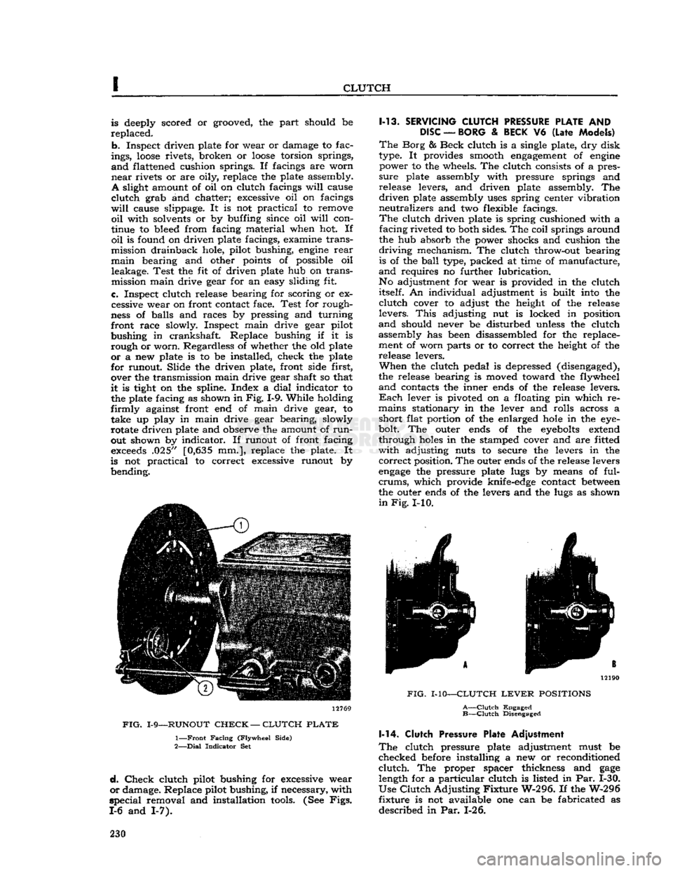
is tight on the spline. Index a
dial
indicator to the plate facing as shown in
Fig.
1-9. While holding
firmly
against front end of main drive gear, to take up play in main drive gear bearing, slowly
rotate driven plate and observe the amount of
run
out shown by indicator. If runout of front facing
exceeds
.025" [0,635 mm.], replace the plate. It
is not practical to correct excessive runout by bending. 12769
FIG.
1-9—RUNOUT
CHECK
—
CLUTCH
PLATE
1—
Front
Facing
(Flywheel
Side)
2—
Dial
Indicator
Set
d.
Check
clutch pilot bushing for excessive wear
or
damage. Replace pilot bushing, if necessary, with
special
removal and installation
tools.
(See
Figs.
1-6 and 1-7). 1-13.
SERVICING
CLUTCH
PRESSURE
PLATE
AND
DISC
—
BORG
&
BECK
V6
(Late
Models)
The
Borg & Beck clutch is a single plate, dry disk
type. It provides smooth
engagement
of
engine
power to the wheels. The clutch consists of a pres
sure
plate assembly with pressure springs and
release levers, and driven plate assembly. The
driven
plate assembly
uses
spring center vibration
neutralizes and two flexible facings.
The
clutch driven plate is spring cushioned with a facing riveted to both sides. The coil springs around
the hub absorb the power shocks and cushion the
driving
mechanism. The clutch throw-out bearing is of the
ball
type, packed at time of manufacture,
and
requires no further lubrication.
No adjustment for wear is provided in the clutch itself. An individual adjustment is built into the
clutch
cover to adjust the height of the release
levers.
This
adjusting nut is locked in position
and
should never be disturbed unless the clutch assembly has been disassembled for the replace
ment of worn parts or to correct the height of the release levers.
When
the clutch pedal is depressed (disengaged),
the release bearing is moved toward the flywheel
and
contacts the inner ends of the release levers.
Each
lever is pivoted on a floating pin which re
mains stationary in the lever and rolls across a short flat portion of the enlarged
hole
in the eye-
bolt. The outer ends of the
eyebolts
extend
through
holes
in the stamped cover and are fitted
with
adjusting nuts to secure the levers in the
correct
position. The outer ends of the release levers
engage
the pressure plate lugs by means of ful-
crums,
which provide knife-edge contact
between
the outer ends of the levers and the lugs as shown
in
Fig.
I-10. 12190
FIG.
MO—CLUTCH
LEVER
POSITIONS
A—Clutch
Engaged
B—Clutch
Disengaged 1-14.
Clutch
Pressure Plate Adjustment
The
clutch pressure plate adjustment must be
checked before installing a new or reconditioned
clutch.
The proper spacer thickness and
gage
length for a particular clutch is listed in Par. 1-30.
Use
Clutch
Adjusting
Fixture
W-296. If the W-296
fixture is not available one can be fabricated as
described in Par. 1-26. 230
Page 235 of 376
![JEEP CJ 1953 Service Manual
Jeep
UNIVERSAL
SERIES
SERVICE
MANUAL
I thickness: .285"
[0,724
cm.], .305"
[0,775
cm.].
Each
spacer should be hardened and ground to size, and then have the dimensional thickness
sta JEEP CJ 1953 Service Manual
Jeep
UNIVERSAL
SERIES
SERVICE
MANUAL
I thickness: .285"
[0,724
cm.], .305"
[0,775
cm.].
Each
spacer should be hardened and ground to size, and then have the dimensional thickness
sta](/img/16/57040/w960_57040-234.png)
'Jeep'
UNIVERSAL
SERIES
SERVICE
MANUAL
I thickness: .285"
[0,724
cm.], .305"
[0,775
cm.].
Each
spacer should be hardened and ground to size, and then have the dimensional thickness
stamped thereon.
c.
From
flat bar stock at least Vfe" [3 mm.] thick,
make a
gauge
as shown in Fig. 1-22. Harden, grind
to size, and stamp sizes on the
gauge.
1-27.
Clutch Installation
a.
Very
sparingly, apply wheel bearing lubricant
to inner surface of pilot bushing in crankshaft.
Caution:
If
excessive
lubricant is applied to pilot bushing, it
will
run out on face of flywheel when
hot and
ruin
the driven plate facings.
b. Make sure that splines in the driven plate hub
are
clean; apply a light coat of lubricant to splines
of hub and transmission drive gear shaft. Slide plate over gear shaft several times; remove plate
from shaft and wipe off
excess
lubricant.
Caution:
Driven plate facings must be kept clean
and
dry.
c.
Fill
groove
in throwout bearing collar with wheel bearing lubricant. See Fig. 1-23. Make sure
that front bearing retainer of transmission is clean;
apply a light coat of wheel bearing lubricant. Slide
throwout bearing over bearing retainer several times. Remove bearing from retainer and wipe off
excess
lubricant.
12736
FIG.
1-23—LUBRICATION
POINTS
—
CLUTCH
THROWOUT
BEARING
COLLAR
1—Coat
This
Groove 2—Pack
This
Recess
d.
Clean
and apply wheel bearing lubricant to ball
stud in flywheel housing and to the
seat
in clutch
fork.
e.
If disassembled, install pressure plate in the cover assembly, lining up the
groove
on its
edge
with the
groove
on the
edge
of the cover.
Install
pressure plate retracting springs, and the three
drive
strap-to-pressure plate
bolts
and lock washers.
Torque
bolts
11 lb-ft. [1,51 kg-m.].
Note:
The diaphragm
type
clutch assembly is fac
tory calibrated and requires no adjustment
before
installation. Refer to Par. 1-14 to adjust Borg and
Beck
coil spring
type
clutch assembly.
f.
Install
the pressure plate and driven plate on
flywheel. Support both assemblies with a spare
main
drive gear.
Note:
Be certain that
mark
on clutch cover is
aligned with the
mark
made on the flywheel during
clutch removal.
g.
Install
clutch attaching
bolts
and tighten alter nately so that clutch is drawn squarely
into
position
on flywheel.
Each
bolt
must be
tightened
one turn at a time to avoid bending the clutch cover flange.
Torque
bolts
30 to 40 lb-ft. [4,1 a 5,5 kg-m.].
h.
Lubricate
the ball stud and clutch fork with
wheel bearing lubricant and install clutch fork.
Note:
Be certain that fork retaining spring is
tight
on pivot ball stud.
i.
Install
flywheel housing on
engine
cylinder
block.
Caution:
Be certain that dowel pins are installed
in
cylinder block.
j.
Lubricate
the recess on the inside of the throw-
out bearing collar. Be careful not to use too much
lubricant.
See Fig. 1-23.
Caution:
Make certain that the lips of the spring
retainer (attached to the clutch fork) are in
groove
of the bearing. See Fig. 1-24.
k.
Install
throwout bearing assembly and connect
clutch linkage.
I.
Install
transmission as described in Section J. m. Adjust clutch for %"
[19,05
mm.] free travel,
see
Par.
1-3. 235
Page 276 of 376
L
PROPELLER
SHAFTS
AND
UNIVERSAL JOINTS
move
the snap rings, pinch the ends
together
with
a
pair
of pliers. If the rings do not readily snap
out of the groove, tap the end of the bearing lightly
which
will
relieve pressure against the rings.
After
removing the snap rings, press on the end of
one bearing until the
opposite
bearing is pushed
from
the yoke arm.
Turn
the joint over and press
the first bearing back out of that arm by pressing
on the
exposed
end of the
journal
shaft. Use a
soft
ground drift with a flat face about [0,8 mm.]
smaller
in diameter than the
hole
in the yoke arm
and
drive it out, otherwise there is danger of damaging the bearing.
Repeat
this operation for the other two bearings,
then lift out
journal
assembly by sliding it to one
side.
L-4.
Snap
Ring
Type Assembly
Wash
all parts in cleaning solvent and inspect the
parte
after cleaning. Replace any parts that indicate
extensive
wear.
It is advisable to install new gaskets
on the
journal
assembly regardless of the condition of the old gaskets. Make certain that the grease
channel
in each
journal
trunnion is open.
Pack
the bearing
cones
one-third
full
of lubricant
and
install the rollers.
Draw
the bearings into the end yoke arm and seat
them firmly against the bearing shoulders. Hold
the bearings in a vertical position to prevent the
needles
from dropping out until the joint is as sembled. If the joint binds when assembled, tap
the arms lightly to relieve any pressure on the bear
ings at the end of the
journal.
L-5.
U-Bolt
Type Disassembly
Removal
of the attaching "U"-bolt releases one set
of bearing races. Slide the propeller shaft into the
yoke flange to remove them using care not to
lose
the rollers.
After
the removal of the one set of bearing races,
release the other set by removing the snap rings
in
the
sleeve
yoke by pinching the ends
together
with
a
pair
of pliers. Should the rings
fail
to snap
readily
from the groove, tap the end of the bearing
lightly,
which
will
relieve the pressure against them.
Press
on the end of one bearing, until the
opposite
bearing
is pushed out of the yoke arm.
Turn
the
universal
joint over and press the first bearing out
by pressing on the
exposed
end of the
journal
as
sembly. Use a
soft
ground drift with a flat face about
\{i
[0,8 mm.] smaller in diameter than the
hole
in the yoke
arm
and drive out the bearing.
Lift
the
journal
out by sliding to one side.
Clean
all
parts
and check for wear.
L-6.
U-Bolt Type Assembly
Wash
all parts in cleaning solvent and inspect the
parts
after cleaning. Replace any parts that indicate
extensive
wear.
It is advisable to install new gaskets
on the
journal
assembly regardless of the condition
of the old gaskets. Make certain that the grease
channel
in each
journal
trunnion is open.
Pack
the bearing
cones
one-third
full
of lubricant
and
install the rollers.
Draw
the bearings into the end yoke arm and seat
them firmly against the bearing shoulders. Hold the
bearings in a vertical position to prevent the
needles
from dropping out until the joint is as
sembled. If the joint binds when assembled, tap the arms lightly to relieve any pressure on the
bearings at the end of the
journal.
Tighten the
U-bolts equally. U-bolt torque wrench reading is 15 to 20 lb-ft. [2,07 a 2,76 kg-m.].
When
installing the assembly in the vehicle be sure
that the arrows on the propeller shaft and yoke
sleeve
are in alignment as shown in Fig. L-2, or
that the unmarked joints are aligned with the yokes in the same parallel plane.
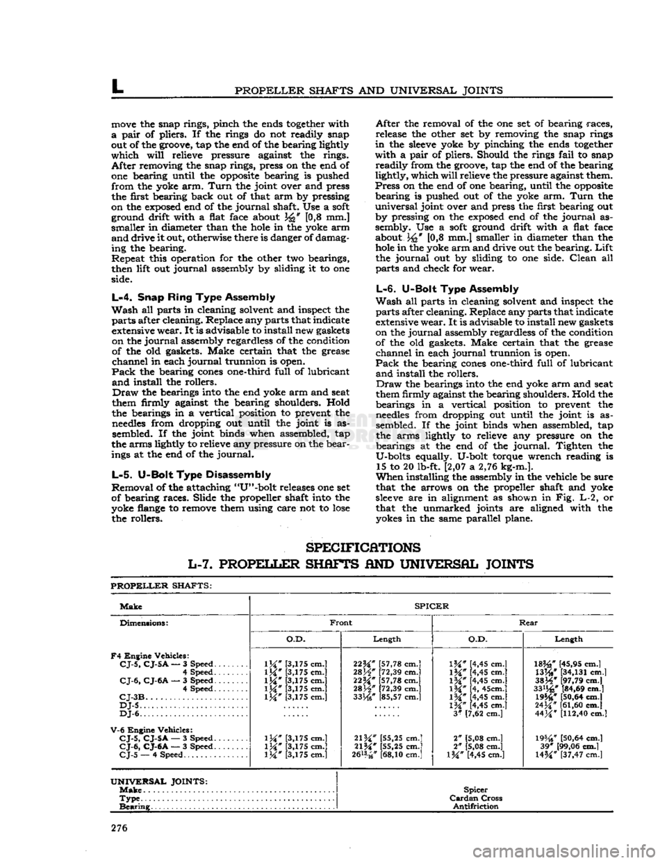
SPECIFICATIONS
L-7.
PROPELLER
SHAFTS
AND
UNIVERSAL JOINTS
PROPELLER
SHAFTS:
Make
SPICER
Dimensions:
F4
Engine Vehicles:
CJ-5,
CJ-5
A
— 3 Speed.
......
4 Speed
CJ-6,
CJ-6A
— 3 Speed 4 Speed
CJ-3B
DJ-5
DJ-6.
V-6
Engine Vehicles:
CJ-5,
CJ-5A
— 3 Speed.
CJ-6,
CJ-6A
— 3 Speed.
CJ-5
— 4 Speed
Front
Rear
Dimensions:
F4
Engine Vehicles:
CJ-5,
CJ-5
A
— 3 Speed.
......
4 Speed
CJ-6,
CJ-6A
— 3 Speed 4 Speed
CJ-3B
DJ-5
DJ-6.
V-6
Engine Vehicles:
CJ-5,
CJ-5A
— 3 Speed.
CJ-6,
CJ-6A
— 3 Speed.
CJ-5
— 4 Speed
O.D.
Length
O.D.
Length
Dimensions:
F4
Engine Vehicles:
CJ-5,
CJ-5
A
— 3 Speed.
......
4 Speed
CJ-6,
CJ-6A
— 3 Speed 4 Speed
CJ-3B
DJ-5
DJ-6.
V-6
Engine Vehicles:
CJ-5,
CJ-5A
— 3 Speed.
CJ-6,
CJ-6A
— 3 Speed.
CJ-5
— 4 Speed
1M"
[3,175 cm.]
1M*
[3,175 cm.]
\W
[3,175 cm.]
1M*
[3,175 cm.] [3,175 cm.]
\W
[3,175 cm.]
\W
[3,175 cm.] [3,175 cm.] 22^" [57,78 cm.]
28H"
[72,39 cm.]
22M*
[57,78 cm.]
mW
[72,39 cm.]
33He"
[85,57 cm.]
21W
[55,25 cm.]
21%"
[55,25 cm.]
2&*
cm.]
IK"
[4,45 cm.]
1M#
[4,45 cm.]
\%"
[4,45 cm.]
\%"
[4, 45cm.]
IW
[4,45 cm.]
1M*
[4,45 cm.]
3*
[7,62 cm.]
2" [5,08 cm.]
2" [5,08 cm.]
l%" [4,45 cm.]
182£"
[45,95 cm.]
WW
[34,131
cm.]
3SJ4*
[97,79 cm.]
33%"
[84,69 cm.] 19546*
[50,64
cm.]
24^"
[61,60
cm.]
44M*
[112,40
cm.]
19%?
[50,64
cm.] 39* [99,06 cm.]
U%"
[37,47 cm.l
UNIVERSAL
JOINTS:
Make
Spicer
Cardan
Cross
Antifriction
Type
Spicer
Cardan
Cross
Antifriction
Bearing
Spicer
Cardan
Cross
Antifriction
276