ECO mode JEEP CJ 1953 Service Manual
[x] Cancel search | Manufacturer: JEEP, Model Year: 1953, Model line: CJ, Model: JEEP CJ 1953Pages: 376, PDF Size: 19.96 MB
Page 10 of 376
B
LUBRICATION
B-2.
Special Lubricants
Special
lubricants are required for certain
lubri
cation points on the 'Jeep' Universal vehicles. The
special
lubricants are necessary for proper function ing and maintenance of the vehicle. The
Lubrica
tion
Chart
(Fig. B-l and B-2)
designates
the spe
cial
lubricating points and identifies them by type
or
part number.
B-3.
Applying
Fresh
Lubricant
When
servicing or lubricating the vehicle, it is important that all old lubricant and
dirt
be re moved from the fitting and/or plugs before servic
ing and that the recommended type of lubricant be used for the particular item being serviced.
Force
lubricant through the lube fittings until the lubricant being forced out of the joint is fresh
lubricant,
indicating that all old lubricant has
been removed.
B-4.
Engine
Lubrication
System —
Hurricane
F4 Engine
•
Refer to Fig. B-3.
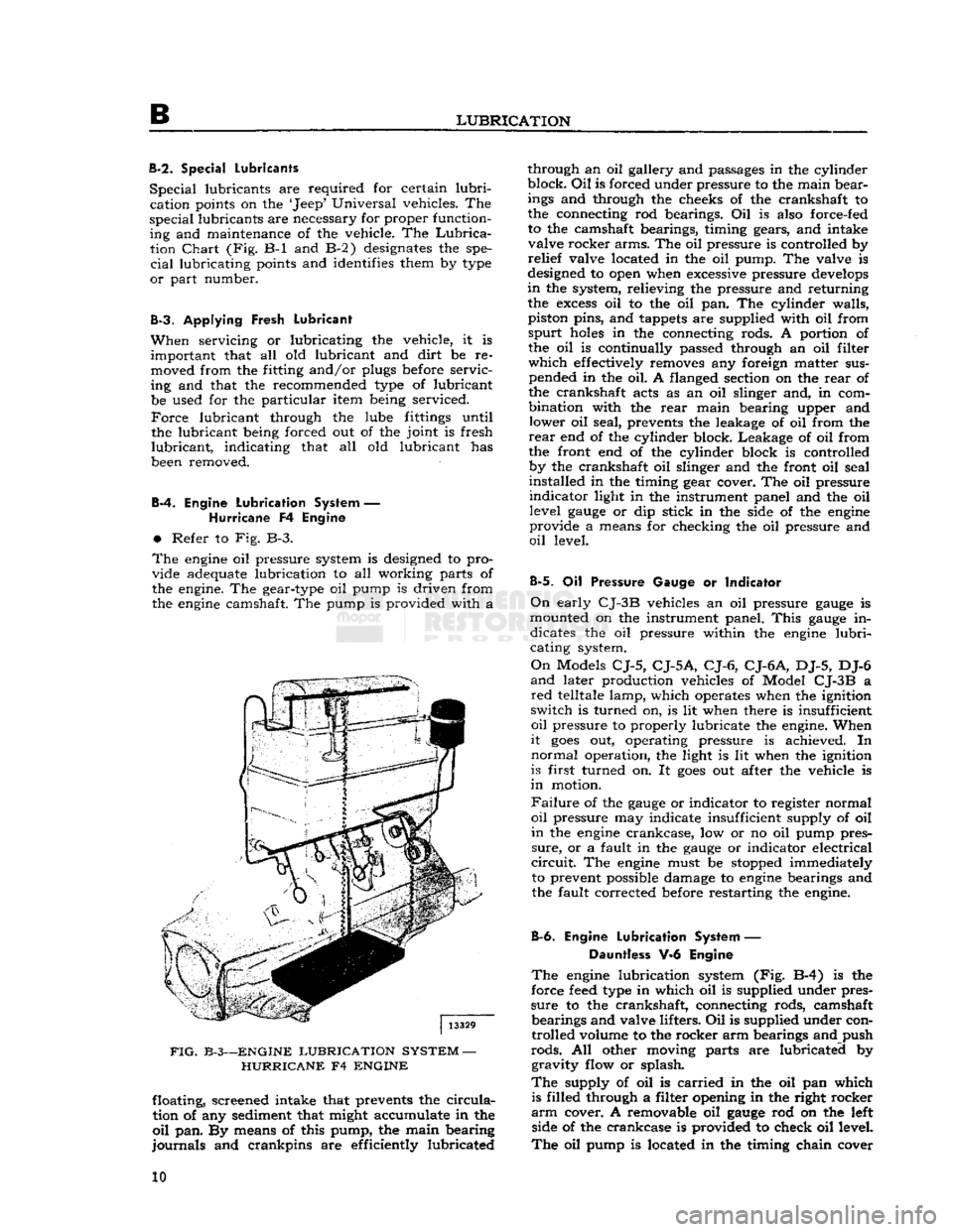
The
engine
oil pressure system is designed to pro
vide adequate lubrication to all working parts of
the engine. The gear-type oil pump is driven from
the
engine
camshaft. The pump is provided with a
FIG.
B-3—ENGINE
LUBRICATION
SYSTEM
—
HURRICANE
F4
ENGINE
floating, screened intake that prevents the
circula
tion of any sediment that might accumulate in the
oil
pan. By means of this pump, the main bearing
journals
and crankpins are efficiently lubricated through an oil gallery and passages in the cylinder
block.
Oil
is forced under pressure to the main bear
ings and through the cheeks of the crankshaft to
the connecting rod bearings. Oil is also force-fed
to the camshaft bearings, timing gears, and intake valve rocker arms. The oil pressure is controlled by
relief
valve located in the oil pump. The valve is
designed to open when excessive pressure
develops
in
the system, relieving the pressure and returning the
excess
oil to the oil pan. The cylinder walls,
piston pins, and tappets are supplied with oil from
spurt
holes
in the connecting rods. A portion of the oil is continually passed through an oil filter
which
effectively removes any foreign matter sus pended in the oil. A flanged section on the
rear
of
the crankshaft acts as an oil slinger and, in com
bination with the
rear
main bearing upper and lower oil seal, prevents the leakage of oil from the
rear
end of the cylinder block. Leakage of oil from
the front end of the cylinder block is controlled by the crankshaft oil slinger and the front oil seal
installed in the timing gear cover. The oil pressure
indicator
light in the instrument panel and the oil level
gauge
or dip stick in the side of the
engine
provide a means for checking the oil pressure and
oil
level.
B-5.
Oil Pressure Gauge or Indicator
On
early
CJ-3B
vehicles an oil pressure
gauge
is
mounted on the instrument panel.
This
gauge
in dicates the oil pressure within the
engine
lubri
cating system.
On
Models
CJ-5,
CJ-5A,
CJ-6,
CJ-6A,
DJ-5, DJ-6
and
later production vehicles of Model
CJ-3B
a
red
telltale lamp, which operates when the ignition
switch is turned on, is lit when there is insufficient
oil
pressure to properly lubricate the engine. When
it
goes
out, operating pressure is achieved. In
normal
operation, the light is lit when the ignition
is first turned on. It
goes
out after the vehicle is
in
motion.
Failure
of the
gauge
or indicator to register normal
oil
pressure may indicate insufficient supply of oil
in
the
engine
crankcase, low or no oil pump pres
sure,
or a fault in the
gauge
or indicator electrical
circuit.
The
engine
must be stopped immediately to prevent possible damage to
engine
bearings and
the fault corrected before restarting the engine.
B-6.
Engine
Lubrication
System — Dauntless V-6 Engine
The
engine
lubrication system (Fig. B-4) is the
force
feed
type in which oil is supplied under pres
sure
to the crankshaft, connecting rods, camshaft bearings and valve lifters. Oil is supplied under controlled volume to the rocker arm bearings and push
rods.
All other moving parts are lubricated by gravity flow or splash.
The
supply of oil is
carried
in the oil pan which is filled through a filter opening in the right rocker
arm
cover. A removable oil
gauge
rod on the left side of the crankcase is provided to check oil level.
The
oil pump is located in the timing chain cover 10
Page 12 of 376
B
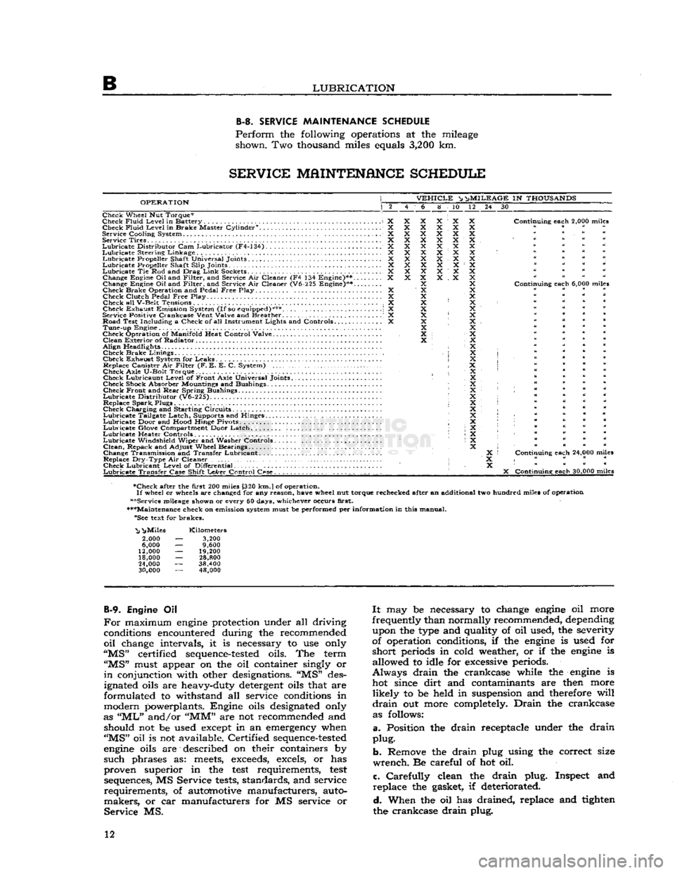
LUBRICATION B-3.
SERVICE
MAINTENANCE
SCHEDULE
Perform
the following operations at the mileage shown. Two thousand miles equals
3,200
km.
SERVICE
MAINTENANCE
SCHEDULE
OPERATION
VEHICLE
^ n>
MILEAGE
IN
THOUSANDS
6 8 10 12 24 30
Check Wheel Nut Torque*
Check
Fluid
Level
in Battery X Check
Fluid
Level
in Brake Master Cylinder0. X
Service
Cooling
System X Service Tires X
Lubricate
Distributor
Cam Lubricator (F4-134) X
Lubricate
Steering Linkage X
Lubricate
Propeller Shaft Universal Joints X
Lubricate
Propeller Shaft
Slip
Joints ; X
Lubricate
Tie Rod and Drag
Link
Sockets................................... X Change Engine
Oil
and
Filter,
and Service Air Cleaner (F4 134 Engine)** X
Change Engine Oil and
Filter,
and Service Air Cleaner (V6-225 Engine)**....
Check Brake Operation and Pedal
Free
Play X Check
Clutch
Pedal
Free
Play. .... X
Check all
V-Belt
Tensions X
Check Exhaust Emission System
(If
so equipped)*** \ X
Service Positive
Crankcase
Vent
Valve
and Breather . .' X
Road Test
Including
a Check of all Instrument
Lights
and Controls X Tune-up Engine
Check Operation of
Manifold
Heat
Control
Valve
Clean
Exterior of Radiator
Align
Headlights • Check Brake
Linings
,
Check Exhaust System for Leaks Replace Canister Air
Filter
(F. E. E. C. System)
Check
Axle
U-Bolt
Torque. Check Lubricaunt
Level
of Front
Axle
Universal Joints
Check Shock Absorber Mountings and Bushings Check Front and
Rear
Spring Bushings
Lubricate
Distributor
(V6-225).
Replace Spark, Plugs
Check Charging and Starting Circuits
Lubricate
Tailgate Latch, Supports and Hinges.
Lubricate
Door and
Hood
Hinge Pivots ;
Lubricate
Glove Compartment Door Latch
Lubricate
Heater Controls •
Lubricate
Windshield
Wiper and Washer Controls
Clean,
Repack and
Adjust
Wheel Bearings
Change Transmission and Transfer Lubricant. .
Replace
Dry-Type
Air Cleaner • Check Lubricant
Level
of
Differential
Lubricate
Transfer
Case
Shift
LeArer
Control
C«se.
. , . . . . . . . .
Continuing
each
2,000 miles
Continuing
each
6,000 miles
Continuing
each
24,000 miles
X
Continuing
each
30,000 miles
•Check after the
first
200 miles [320
km.
J
of operation.
If
wheel or wheels are changed for any
reason,
have
wheel nut torque rechecked after an additional two hundred miles of operation
••Service mileage shown or every 60 days, whichever occurs
first.
•••Maintenance check on emission system must be performed per
information
in this manual. "See text for brakes.
"Nj
^Miles
2,000
6,000
12,000
18,000
24,000
30,000
Kilometers
3,200
9,600
19,200
28,800
38,400 48,000
B-9.
Engine Oil
For
maximum
engine
protection under all driving conditions encountered during the recommended
oil
change intervals, it is necessary to use only
"MS"
certified
sequence-tested
oils. The term
"MS"
must appear on the oil container singly or
in
conjunction with other designations. "MS" des
ignated oils are heavy-duty detergent oils that are
formulated to withstand all service conditions in
modern powerplants. Engine oils designated only
as
"ML"
and/or
"MM"
are not recommended and should not be used except in an emergency when
"MS"
oil is not available. Certified
sequence-tested
engine
oils are described on their containers by
such
phrases as:
meets,
exceeds,
excels, or has
proven superior in the
test
requirements,
test
sequences, MS Service
tests,
standards, and service
requirements,
of automotive manufacturers, auto
makers,
or car manufacturers for MS service or
Service
MS.
It
may be necessary to change
engine
oil more
frequently than normally recommended, depending upon the type and quality of oil used, the severity
of operation conditions, if the
engine
is used for
short
periods in cold weather, or if the
engine
is allowed to idle for excessive periods.
Always
drain
the crankcase while the
engine
is hot since
dirt
and contaminants are then more
likely
to be held in suspension and therefore
will
drain
out more completely.
Drain
the crankcase as follows:
a.
Position the
drain
receptacle under the
drain
plug.
b.
Remove the
drain
plug using the correct size
wrench.
Be careful of hot oil.
c.
Carefully
clean the
drain
plug. Inspect and
replace
the gasket, if deteriorated.
d.
When the oil has drained, replace and tighten
the crankcase
drain
plug. 12
Page 15 of 376
'Jeep*
UNIVERSAL SERIES SERVICE
MANUAL
B
solvent.
Wrap
the polyurethane element in a clean
dry
cloth and
squeeze
to remove all possible sol
vent. Do not wring the element or it may
become
torn.
After cleaning, oil the polyurethane element
liberally
with
engine
oil
(SAE
10W30) and
squeeze
to evenly distribute the oil through the element and to remove
excess
oil. The element should be damp
with
oil, not dripping.
Install
the polyurethane element on the paper element, taking care to have
edges
of the polyurethane element over the plastic end plates of the paper element.
Replace
the complete air cleaner element assembly every
24,000
miles
[38.400
km.]. Replace more
frequently if there is any apparent damage or evidence of plugging.
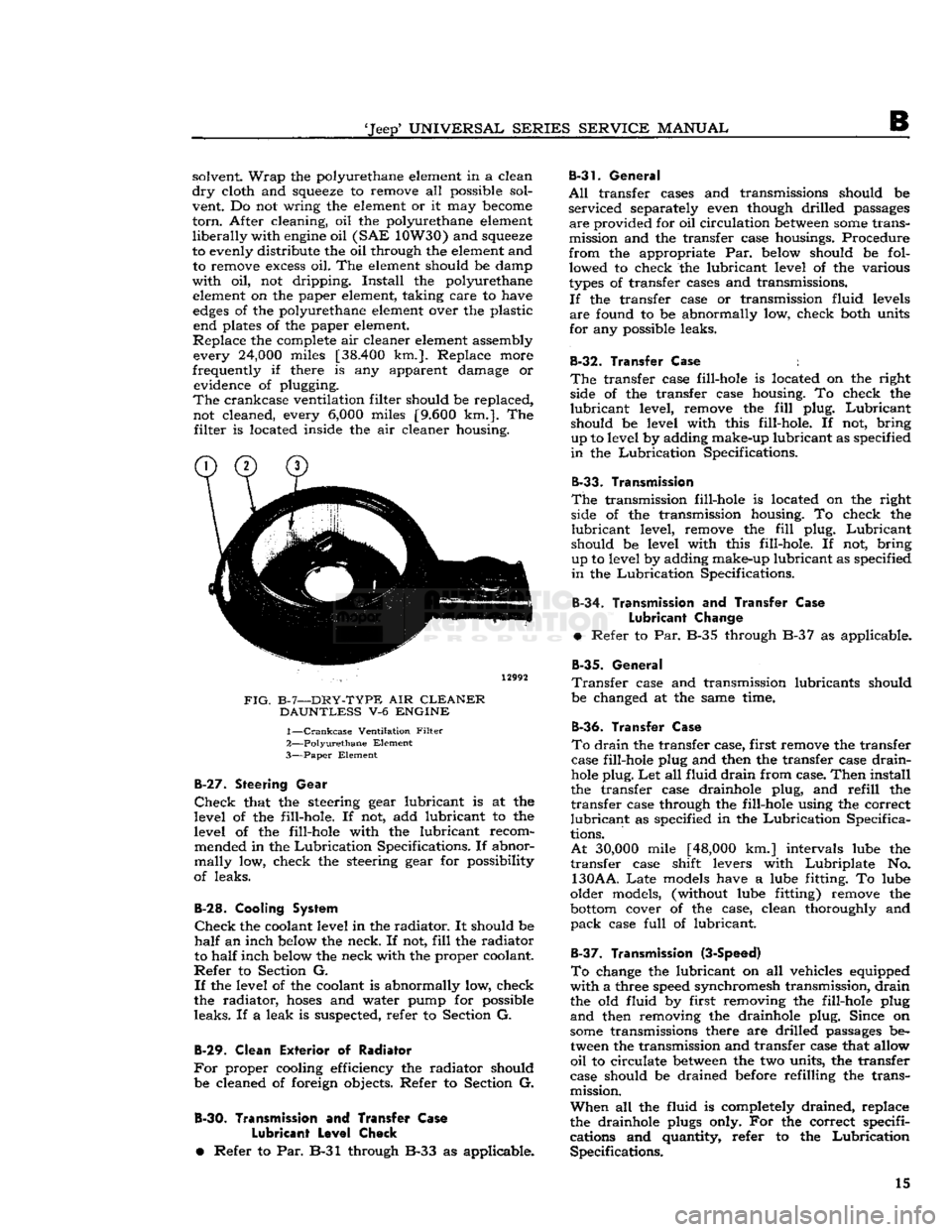
The
crankcase ventilation filter should be replaced, not cleaned, every
6,000
miles
[9.600
km.]. The
filter
is located inside the air cleaner housing.
12992
FIG.
B-7—DRY-TYPE
AIR
CLEANER DAUNTLESS
V-6
ENGINE
1—
Crankcase
Ventilation
Filter
2—
Polyurethane
Element
3—
Paper
Element
B-27.
Steering
Gear
Check
that the steering gear lubricant is at the
level of the fill-hole. If not, add lubricant to the
level of the fill-hole with the lubricant recom mended in the
Lubrication
Specifications. If abnor
mally
low, check the steering gear for possibility
of leaks.
B-28.
Cooling System
Check
the coolant level in the
radiator.
It should be
half
an inch below the neck. If not,
fill
the radiator
to
half
inch below the neck with the proper coolant.
Refer
to Section G.
If
the level of the coolant is abnormally low, check
the radiator,
hoses
and water pump for possible
leaks.
If a leak is suspected, refer to Section G.
B-29.
Clean
Exterior
of Radiator
For
proper cooling efficiency the radiator should be cleaned of foreign objects. Refer to Section G.
B-30.
Transmission
and
Transfer Case
Lubricant
Level
Cheek
•
Refer to Par. B-31 through B-33 as applicable.
B-31.
General
All
transfer cases and transmissions should be
serviced
separately even though drilled passages
are
provided for oil circulation
between
some
trans
mission and the transfer case housings. Procedure
from
the appropriate Par. below should be fol lowed to check the lubricant level of the various
types
of transfer cases and transmissions.
If
the transfer case or transmission fluid levels
are
found to be abnormally low, check both units
for any possible leaks.
B-32.
Transfer
Case
:
The
transfer case fill-hole is located on the right side of the transfer case housing. To check the
lubricant
level, remove the
fill
plug.
Lubricant
should be level with this fill-hole. If not, bring up to level by adding make-up lubricant as specified
in
the
Lubrication
Specifications.
B-33.
Transmission
The
transmission fill-hole is located on the right side of the transmission housing. To check the
lubricant
level, remove the
fill
plug.
Lubricant
should be level with this fill-hole. If not, bring
up to level by adding make-up
lubricant
as specified
in
the
Lubrication
Specifications.
B-34.
Transmission and Transfer
Case
Lubricant
Change
•
Refer to Par. B-35 through B-37 as applicable.
B-35.
General
Transfer
case and transmission lubricants should
be changed at the same time.
B-36.
Transfer
Case
To
drain
the transfer case, first remove the transfer
case fill-hole plug and then the transfer case
drain-
hole
plug. Let all fluid
drain
from case.
Then
install
the transfer case drainhole plug, and
refill
the
transfer
case through the fill-hole using the correct
lubricant
as specified in the
Lubrication
Specifica
tions.
At
30,000
mile
[48,000
km.] intervals lube the
transfer
case shift levers with
Lubriplate
No.
130AA.
Late
models have a lube fitting. To lube
older models, (without lube fitting) remove the
bottom
cover of the case, clean thoroughly and
pack
case
full
of lubricant.
B-37.
Transmission (3-Speed)
To
change the lubricant on all vehicles equipped
with
a three speed synchromesh transmission,
drain
the old fluid by first removing the fill-hole plug
and
then removing the drainhole plug. Since on
some
transmissions there are drilled passages be tween the transmission and transfer case that allow
oil
to circulate
between
the two units, the transfer
case should be drained before refilling the trans
mission.
When
all the fluid is completely drained, replace
the drainhole plugs only. For the correct specifi
cations and quantity, refer to the
Lubrication
Specifications. 15
Page 31 of 376
'Jeep'
UNIVERSAL
SERIES
SERVICE
MANUAL
C
FIG.
C-22—-CHECKING
FUEL
PUMP
PRESSURE
—
DAUNTLESS
V-6
ENGINE a
couple of strokes to be sure the pump is primed.
Using
a half-pint
bottle
or similar measure, pump
Vi
pint [0,24 It] of fuel by cranking the
engine
with
the starter motor. Count the strokes neces
sary
to
fill
the measure. If more than 20 strokes
are
required, the fuel pump is inefficient, the tank
line is leaking air, or the fuel supply is restricted.
Check
fuel filter in the fuel tank if line is restricted.
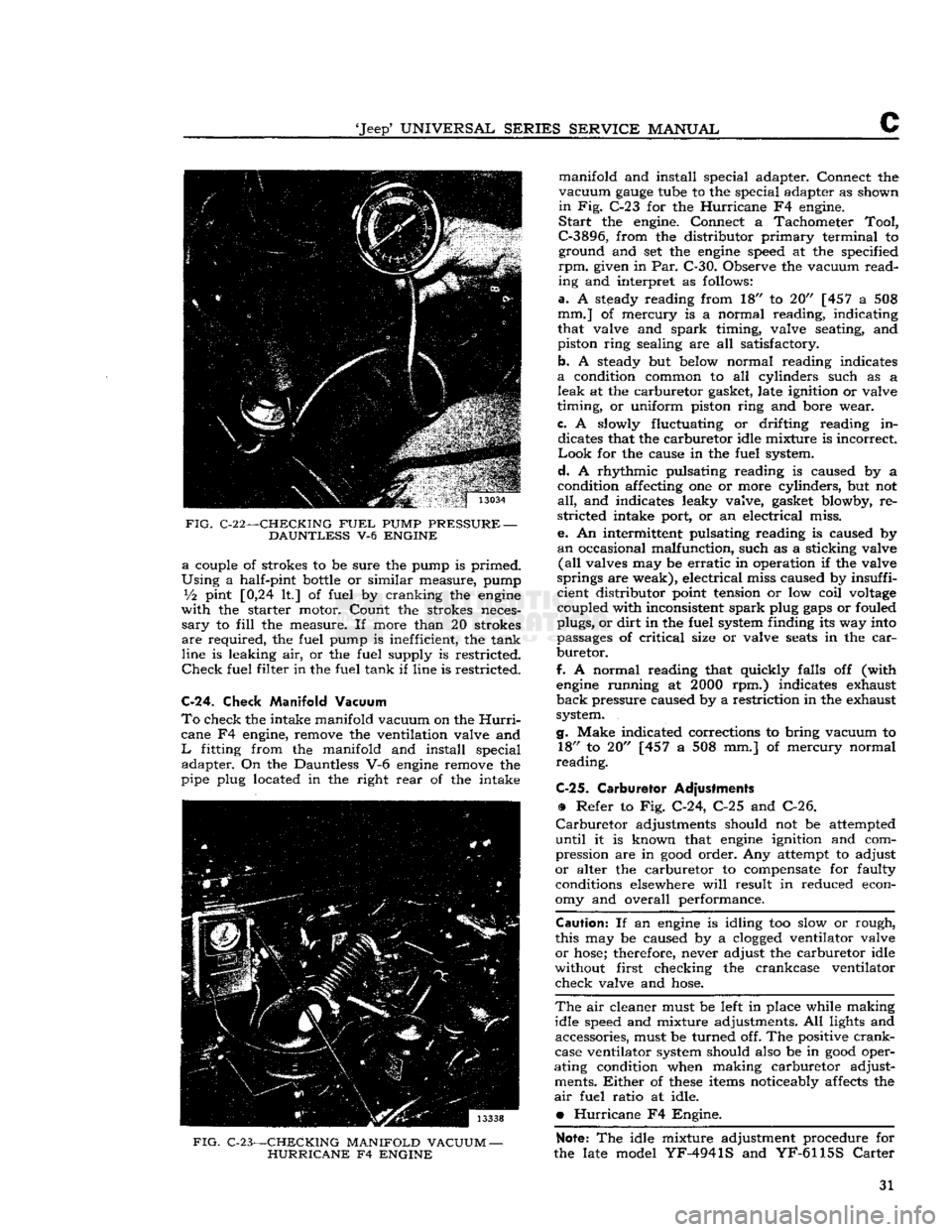
C-24.
Check Manifold Vacuum
To
check the intake manifold vacuum on the
Hurri
cane F4 engine, remove the ventilation valve and
L
fitting from the manifold and install special adapter. On the Dauntless V-6
engine
remove the
pipe plug located in the right
rear
of the intake
FIG.
C-23—CHECKING MANIFOLD VACUUM
—
HURRICANE
F4
ENGINE
manifold and install special adapter. Connect the
vacuum
gauge
tube to the special adapter as shown
in
Fig. C-23 for the
Hurricane
F4 engine.
Start
the engine. Connect a Tachometer
Tool,
C-3896,
from the distributor
primary
terminal to ground and set the
engine
speed at the specified
rpm.
given in Par. C-30. Observe the vacuum
read
ing and interpret as follows:
a.
A steady reading from 18" to 20" [457 a 508
mm.] of mercury is a normal reading, indicating
that valve and
spark
timing, valve seating, and
piston ring sealing are all satisfactory.
b. A steady but below normal reading indicates
a
condition common to all cylinders such as a
leak
at the carburetor gasket, late ignition or valve
timing, or uniform piston ring and bore wear.
c.
A slowly fluctuating or drifting reading in dicates that the carburetor idle mixture is incorrect
Look
for the cause in the fuel system.
d.
A rhythmic pulsating reading is caused by a
condition affecting one or more cylinders, but not
all,
and indicates leaky valve, gasket blowby, re
stricted intake port, or an electrical miss.
e. An intermittent pulsating reading is caused by
an
occasional malfunction, such as a sticking valve
(all
valves may be
erratic
in operation if the valve
springs are weak), electrical miss caused by insuffi
cient distributor point tension or low coil
voltage
coupled with inconsistent
spark
plug
gaps
or fouled
plugs, or
dirt
in the fuel system finding its way into
passages of
critical
size or valve
seats
in the
car
buretor.
f.
A normal reading that quickly falls off (with
engine
running at
2000
rpm.) indicates exhaust
back
pressure caused by a restriction in the exhaust
system.
g.
Make indicated corrections to bring vacuum to 18" to 20" [457 a 508 mm.] of mercury normal
reading.
C-25.
Carburetor Adjustments
•
Refer to Fig. C-24, C-25 and C-26.
Carburetor
adjustments should not be attempted
until
it is known that
engine
ignition and com
pression are in
good
order. Any attempt to adjust
or
alter the carburetor to compensate for faulty conditions elsewhere
will
result in reduced econ
omy and overall performance.
Caution:
If an
engine
is idling too slow or rough,
this may be caused by a
clogged
ventilator valve
or
hose;
therefore, never adjust the carburetor idle
without first checking the crankcase ventilator
check valve and
hose.
The
air cleaner must be left in place while making
idle speed and mixture adjustments. All lights and accessories, must be turned off. The positive
crank
case ventilator system should also be in
good
oper
ating condition when making carburetor adjust ments.
Either
of
these
items noticeably affects the
air
fuel ratio at idle.
•
Hurricane
F4 Engine.
Note:
The idle mixture adjustment procedure for
the late model
YF-4941S
and
YF-6115S
Carter
31
Page 85 of 376
'Jeep*
UNIVERSAL
SERIES SERVICE
MANUAL
Dl
12713
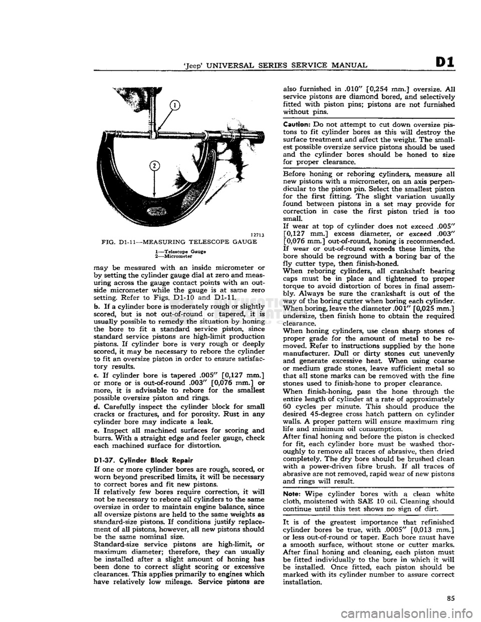
FIG.
Dl-11—MEASURING
TELESCOPE GAUGE
1—
Telescope
Gauge
2—
Micrometer
may
be measured with an inside micrometer or
by setting the cylinder
gauge
dial
at zero and meas
uring
across the
gauge
contact points with an outside micrometer while the
gauge
is at same zero
setting. Refer to
Figs.
Dl-10 and Dl-11.
b.
If a cylinder bore is moderately rough or slightly
scored,
but is not out-of-round or tapered, it is
usually
possible to remedy the situation by honing
the bore to fit a standard service piston, since
standard
service pistons are high-limit production
pistons. If cylinder bore is very rough or deeply
scored,
it may be necessary to rebore the cylinder
to fit an oversize piston in order to ensure satisfac
tory
results.
c.
If cylinder bore is tapered .005" [0,127 mm.]
or
more or is out-of-round .003" [0,076 mm.] or
more,
it is advisable to rebore for the smallest possible oversize piston and rings.
d.
Carefully
inspect the cylinder block for small
cracks
or fractures, and for porosity.
Rust
in any
cylinder
bore may indicate a leak.
e.
Inspect all machined surfaces for scoring and
burrs.
With
a straight
edge
and feeler
gauge,
check
each
machined surface for distortion.
D1-37.
Cylinder Block Repair
If
one or more cylinder bores are rough, scored, or
worn
beyond prescribed limits, it
will
be necessary
to correct bores and fit new pistons.
If
relatively few bores require correction, it
will
not be necessary to rebore all cylinders to the same
oversize in order to maintain
engine
balance, since
all
oversize pistons are held to the same weights as
standard-size
pistons. If conditions justify replace
ment of all pistons, however, all new pistons should
be the same nominal size.
Standard-size
service pistons are high-limit, or
maximum
diameter; therefore, they can usually be installed after a slight amount of honing has
been
done
to correct slight scoring or excessive
clearances.
This
applies
primarily
to
engines
which
have relatively low mileage. Service pistons are also furnished in .010"
[0,254
mm.] oversize. All
service
pistons are diamond bored, and selectively
fitted with piston pins; pistons are not furnished
without pins.
Caution:
Do not attempt to cut down oversize pis
tons
to fit cylinder bores as this
will
destroy the
surface
treatment and affect the weight. The small
est possible oversize service pistons should be used
and
the cylinder bores should be honed to size
for
proper clearance.
Before
honing or reboring cylinders, measure all new pistons with a micrometer, on an axis perpen
dicular
to the piston pin. Select the smallest piston
for
the first fitting. The slight variation usually
found between pistons in a set may provide for
correction
in case the first piston tried is too
small.
If
wear at top of cylinder
does
not exceed .005" [0,127 mm.]
excess
diameter, or exceed .003"
[0,076 mm.] out-of-round, honing is recommended.
If
wear or out-of-round
exceeds
these
limits, the
bore should be reground with a boring bar of the
fly
cutter type, then finish-honed.
When
reboring cylinders, all crankshaft bearing caps must be in place and tightened to proper
torque to avoid distortion of bores in
final
assem
bly.
Always be sure the crankshaft is out of the
way
of the boring cutter when boring each cylinder.
When
boring, leave the diameter .001" [0,025 mm.]
undersize,
then finish hone to obtain the required
clearance.
When
honing cylinders, use clean sharp
stones
of
proper
grade for the amount of metal to be re
moved. Refer to instructions supplied by the hone
manufacturer.
Dull
or dirty
stones
cut unevenly
and
generate excessive heat. When using coarse
or
medium grade
stones,
leave sufficient metal so
that all
stone
marks can be removed with the fine
stones
used to finish-hone to proper clearance.
When
finish-honing, pass the hone through the entire length of cylinder at a rate of approximately 60 cycles per minute.
This
should produce the
desired
45-degree
cross hatch pattern on cylinder
walls.
A proper pattern
will
ensure maximum
ring
life and minimum oil consumption.
After
final
honing and before the piston is checked
for
fit, each cylinder bore must be washed thor oughly to remove all traces of abrasive, then dried completely. The dry bore should be brushed clean
with
a power-driven fibre
brush.
If all traces of
abrasive
are not removed,
rapid
wear of new pistons
and
rings
will
result.
Note:
Wipe cylinder bores with a clean white
cloth,
moistened with SAE 10 oil. Cleaning should
continue until this
test
shows no sign of
dirt.
It
is of the greatest importance that refinished
cylinder
bores be true, with .0005" [0,013 mm.]
or
less out-of-round or taper.
Each
bore must have
a
smooth surface, without
stone
or cutter
marks.
After
final
honing and cleaning, each piston must be fitted individually to the bore in which it
will
be installed. Once fitted, each piston should be
marked
with its cylinder number to assure correct
installation.
85
Page 113 of 376
'Jeep*
UNIVERSAL
SERIES
SERVICE
MANUAL
E
there is a relief valve that
opens
to reduce high
(dangerous) pressures in the fuel tank. In con
junction
with the pressure relief valve there is a
vacuum
relief valve to
stop
collapse of the fuel
tank
in case of a plugged system or failure of the demand valve. When replacing the gas cap, the
same type must be used as originally installed.
E-8.
System Inspection Test
The
fuel emission vent system should be checked
carefully
to ensure the absence of any leaks to the
atmosphere of either liquid or vapor which might
affect the accuracy, safety, or performance of the control system.
To
assure that the sealed system has been properly
installed,
the following
test
procedure has been
developed.
Disconnect the vent line from the fuel tank system
to the activated charcoal canister, induce l/i p.s.i.
air
pressure. If this pressure can be maintained for
a
few seconds the vent system is assured to be sealed. DO NOT add air pressure to the canister
because damage can occur to the demand valve if
care
is not taken.
E-9.
Servicing the System
Periodic
Maintenance — Replace carbon canister filter at
12,000
miles
[19,200
km.] or 12 month intervals (more
often
for operation in dusty areas).
This
is the only regular maintenance service
required.
Canister
Filter
Replacement — Disconnect
hoses
from
top of canister, remove canister from mount
-
t
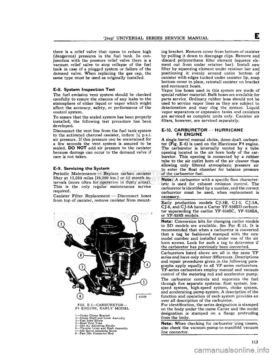
FIG.
E-5—CARBURETOR—
F4 ENGINE,
EARLY
MODEL
1—
Choke
Clamp
Bracket
2—
Choke
Shaft and
Lever
Assembly
3—
Fuel
Inlet
Elbow
4—
Bowl
Vent Tube 5—
Idle
Air Adjusting
Needle
6—
Throttle
Lever
and Shaft Assembly
7—
Idle
Speed Adjusting Screw
8—
Fast
Idle Connector Rod ing bracket. Remove cover from
bottom
of canister
by pulling it down to
disengage
clips. Remove and
discard
polyurethane filter element
(squeeze
ele
ment out from under retainer bar).
Install
new
filter by squeezing element under retainer bar and positioning it evenly around entire
bottom
of
canister with
edges
tucked under canister lip, snap
bottom
cover in place, reinstall canister on bracket
and
reconnect
hoses.
Vapor
line
hoses
used in this system are made of
special
rubber material.
Bulk
hoses
are available for
parts
service.
Ordinary
rubber
hose
should not be
used to service vapor lines as they are subject to deterioration and may clog the system.
Liquid
vapor separators or expansion tanks and canisters
are
serviced as complete units only.
Canister
air filters, however, are serviced separately.
E-10.
CARBURETOR
—
HURRICANE
F4
ENGINE
A
single-barrel manual choke, down-draft carbure
tor (Fig. E-6) is used on the
Hurricane
F4 engine.
The
carburetor is internally vented by a tube
opening located in the air horn body of the
car
buretor.
This
opening is connected by a rubber
tube to the air
outlet
horn of the air cleaner thus
allowing only filtered atmospheric pressure air
to enter the float chamber for balance pressure
of the carburetor fuel.
Note:
A carburetor with a specific flow character
istic
is used for exhaust emission control. The
carburetor
is identified by a number, and the correct
carburetor
must be used, when replacement is
necessary.
Early
production models
CJ-3B,
CJ-5,
CJ-5A,
CJ-6,
and
CJ-6A
have a
Carter
YF-938SD
carbure
tor superseding the earlier
YF-938SC,
YF-938SA,
or
YF-938S
models.
Note."
Conversion kits for changing earlier models
to SD models are available. See Par E-23. It is recommended that when a carburetor is converted
that a tag be fashioned stamped with the new model number and installed under one of the air
horn
screws.
Look
for such a tag to determine if
the carburetor has previously been converted.
Carburetors
listed above are all in the same YF
series and have only minor differences. Descriptions
and
repair procedures given in the following
para
graphs apply equally to all
YF-series
carburetors.
YF-series
carburetors employ manual and vacuum
control of the metering rod and accelerator pump.
The
carburetor controls and vaporizes the fuel
through five separate systems: float system, low-
speed system, high-speed system, choke system,
and
accelerating-pump system. A description of the function and operation of each system provides an over all description of the carburetor.
For
identification, the series designation is stamped
on the body under the name
Carter
and the model
designation is stamped on a flange protruding
from
the body.
Note:
When checking for carburetor icing causes,
also check the vacuum-pump-to-manifold vacuum
line connector. 113
Page 114 of 376
FUEL
SYSTEM
14261
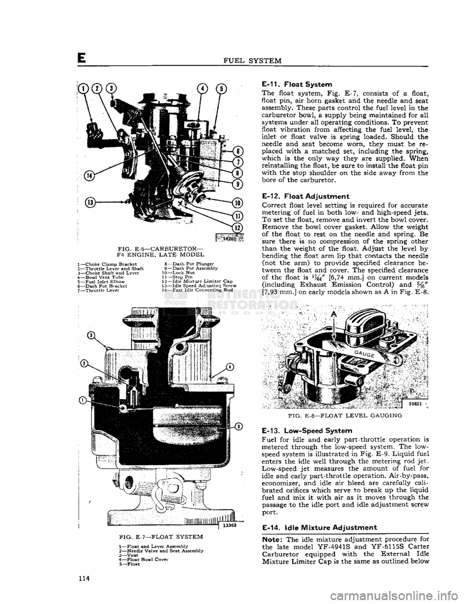
FIG.
E-6—CARBURETOR—
F4 ENGINE,
LATE
MODEL 1—
Choke
Clamp Bracket
2—
Throttle
Lever
and Shaft
3—
Choke
Shaft and
Lever
4—
Bowl
Vent Tube
5—
Fuel
Inlet Elbow
6—
Dash
Pot Bracket 7—
Throttle
Lever
8—
Dash
Pot Plunger
9—
Dash
Pot Assembly
10—
Lock
Nut
11— Stop Pin
1
2—Idle Mixture
Limiter
Cap
13—
Idle
Speed Adjusting Screw 14—
Fast
Idle Connecting Rod
E-11.
Float System
The
float system, Fig. E-7, consists of a float,
float
pin,
air horn gasket and the
needle
and seat assembly. These parts control the fuel level in the
carburetor
bowl, a supply being maintained for all
systems under all operating conditions. To prevent
float
vibration
from affecting the fuel level, the
inlet or float valve is spring loaded. Should the
needle
and seat
become
worn, they must be re
placed
with a matched set, including the spring,
which
is the only way they are supplied. When
reinstalling
the float, be sure to install the float pin
with
the
stop
shoulder on the side away from the bore of the carburetor.
E-12.
Float Adjustment
Correct
float level setting is required for accurate
metering of fuel in both low- and high-speed jets.
To
set the float, remove and invert the bowl cover. Remove the bowl cover gasket. Allow the weight
of the float to rest on the
needle
and spring. Be
sure
there is no compression of the spring other
than
the weight of the float. Adjust the level by
bending the float arm lip that contacts the
needle
(not the arm) to provide specified clearance be
tween the float and cover. The specified clearance of the float is
L74\F
[6,74 mm.] on current models
(including
Exhaust
Emission Control) and [7,93 mm.] on early models shown as A in
Fig.
E-8.
FIG.
E-7—FLOAT SYSTEM
1—
Float
and
Lever
Assembly
2—
Needle
Valve and Seat Assembly
3—
Vent
4—
Float
Bowl Cover 5—
Float
7 '.. j
io8Si
i
FIG.
E-8—FLOAT
LEVEL
GAUGING
E-13.
Low-Speed System
Fuel
for idle and early part-throttle operation is
metered through the low-speed system. The low-
speed system is illustrated in Fig.
E-9.
Liquid
fuel enters the idle well through the metering rod jet.
Low-speed
jet measures the amount of fuel for
idle and early part-throttle operation. Air-by-pass,
economizer, and idle air bleed are carefully
cali
brated
orifices which serve to break up the liquid
fuel
and mix it with air as it
moves
through the passage to the idle port and idle adjustment screw
port.
E-14.
Idle Mixture Adjustment
Note:
The idle mixture adjustment procedure for
the late model
YF-4941S
and
YF-6115S
Carter
Carburetor
equipped with the
External
Idle
Mixture
Limiter
Cap is the same as outlined below 114
Page 118 of 376
E
FUEL
SYSTEM
Note:
Do not remove pressed-in parts such as
nozzle, pump jet, or antipercolator air bleed.
j.
Remove body flange attaching screws, body flange assembly, and gasket.
k.
Remove idle-adjustment screw, spring, idle
port
rivet, throttle lever assembly, washer, fast
idle arm, throttle plate screws, throttle plate, and throttle shaft.
1. Remove throttle shaft seal by prying out seal
retainer.
Note:
Do not remove pressed-in vacuum passage
orifice.
m.
Remove choke valve screws and choke valve.
Unhook
choke spring and slide shaft from housing,
n.
Wash all parts in carburetor cleaning solution
and
blow out passages with compressed air. Do not immerse diaphragm or seals in cleaning solution.
Inspect
all parts for wear or damage. Always use
new gaskets when reassembling.
E-22.
Carburetor
Reassembly
•
Refer to Fig. E-13.
To
expedite
reassembly, it is advisable to group all
related
parts by the circuit to which they belong.
a.
Install
throttle shaft seal and retainer in flange casting.
b.
Install
fast-idle
arm,
washer, and lever assembly
on throttle shaft. Slide shaft into place and install throttle valve.
c.
Install
idle port rivet plug and idle adjusting
screw
and spring.
d.
Attach flange assembly to body casting. Use new gasket.
e.
Install
low-speed jet assembly.
f.
Early
production models install pump intake
strainer
in pump diaphragm housing and carefully
press into recess.
Note:
If strainer is even slightly damaged, a new
one must be installed.
g.
Install
pump diaphragm assembly in diaphragm housing.
Then,
install pump diaphragm spring
(lower)
and retainer.
h.
Install
pump lifter
link,
metering rod
arm,
upper
pump spring, and retainer.
I.
Install
metering rod jet.
Note:
No gasket is used with this jet.
j.
Install
diaphragm housing attaching screws in
the diaphragm housing, making sure that the
edges
of the diaphragm are not wrinkled.
Lower
into place and tighten screws evenly and securely,
k.
Install
throttle shaft seal, dust seal washer, and
shaft seal spring.
I.
Install
pump connector
link
in the throttle arm
assembly.
Install
throttle shaft arm assembly on
throttle shaft guiding connector
link
in pump lifter
link
hole.
CAUTION:
Linkage
must not bind in any throttle
position. If binding occurs,
loosen
clamp screw in
throttle arm, adjust slightly, then retighten screw.
m.
Install
pump check disc, disc retainer, and lock
ring.
n.
Install
metering rod and pin spring. Connect
metering rod spring.
o.
Check
and if necessary correct meter ing rod adjustment. Follow procedure of
Par.
E-16.
p.
Install
needle
seat and gasket assembly, needle,
float
and
float pin. The
stop
shoulder on the float
pin
must be on the side away from the bore of
the carburetor.
q.
Set float level to specifications. Follow pro cedure of
Par.
E-12.
r.
Install
air horn gasket and air horn assembly.
Install
attaching screws, lock washers, and choke
tube clamp assembly. Tighten center screws first,
s. Slide choke shaft and lever assembly into place
and
connect choke lever
spring.
Install
choke valve.
Center
the valve by tapping lightly, then hold in
place with fingers when tightening screws,
t.
Install
fast-idle connector rod with
offset
portion
of rod on top and pin spring on outside.
Install
fast-idle connecting rod spring.
E-23.
Correcting Acceleration
Flat
Spot
Early
production
Carburetor
Models 938-S, 938-
SA,
938-SC
Inasmuch
as a flat
spot
on acceleration or low speed
stumble can
come
from causes other than
car
buretor
malfunction, it is recommended that
engine
tuning be thoroughly checked before attempting
any
actual carburetor work. Make sure that
ignition, compression, and timing are correct and
that fuel pump is supplying enough gas. Also, the F-head
engine
employs a water-heated intake
manifold.
Proper vaporization of the fuel depends
on correct intake manifold temperature. Since this
temperature is controlled by the cooling system
thermostat, include an operational check of the
thermostat when diagnosing the stumble. Operating
temperatures consistently below
155°F.
can cause stumble.
If
the stumble persists, a
YF-938-S,
YF-938-SA,
or
YF-938-SC
carburetor can be converted to a
YF-938-SD
carburetor by installing Special Kit
924161, consisting of a pump discharge check
needle, a metering rod, and a metering rod jet. If this kit is installed, the pump discharge check
needle
replaces the original
ball,
weight, and re
tainer
and the small wire-type retainer used with
the
ball
check assembly must not be reinstalled.
When
installing the kit, check the size of the pump discharge jet, No. 2, Fig. E-14.
Early
production
YF-938S
and
YF-938SA
carburetors have a .025" [0,635 mm.] jet installed. If the carburetor being
converted has a .025" jet it must be opened up to .031" [0,787 mm.] by running a No. 68
drill
through
the jet as shown in
Fig.
E-14.
The jet must be drilled
as it is a pressed in part and cannot be replaced.
Upon
completing the installation of the conversion
kit,
mark
or tag the carburetor to indicate that it
is a
YF-938SD.
118
Page 125 of 376
'Jeep'
UNIVERSAL
SERIES
SERVICE
MANUAL
E
is generally caused by excessive
engine
idle speed
in
combination with retarded ignition timing,
engine
heat soak or the use cf low octane fuel.
Should
engine
dieseling
(engine
running after ignition key is turned off) be experienced on V-6
engine
equipped vehicles, installation of Idle Stop
Valve
Kit
Part
No.
991722
will
correct the
difficulty.
E-43.
Fast
Idle Adjustment
No fast idle speed adjustment is required.
Fast
idle is controlled by the curb idle speed adjustment
screw.
If curb idle speed is correctly set and the choke rod is properly adjusted, fast idle speed
will
be correct;
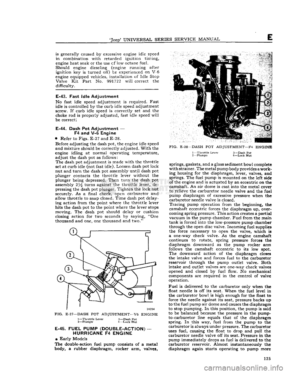
E-44.
Dash Pot Adjustment —
F4
and V-6 Engine
•
Refer to
Figs.
E-27 and E-28. Before adjusting the dash pot, the
engine
idle speed
and
mixture should be correctly adjusted.
With
the
engine
idling at normal operating temperature,
adjust
the dash pot as follows:
The
dash pot adjustment is made with the throttle
set at curb idle (not fast idle). Loosen dash pot lock
nut and
turn
the dash pot assembly until dash pot
plunger contacts the throttle lever without the plunger being depressed.
Then
turn
the dash pot
assembly 2turns against the throttle lever, de pressing the dash pot plunger. Tighten the lock nut
securely. As a final check, open carburetor and
allow throttle to snap closed. Time dash pot delay ing action from the point where the throttle lever
hits the dash pot to the point where the lever
stops
moving. The dash pot should delay or cushion
closing action for two seconds by saying, "One
thousand and one, one thousand and two."
14204
FIG.
E-27—DASH
POT
ADJUSTMENT—V6
ENGINE
1—
Throttle
Lever
3—Dash Pot
2—
Plunger
4—Lock
Nut
E-45.
FUEL
PUMP
(DOUBLE-ACTION)
—
HURRICANE
F4
ENGINE
•
Early
Models
The
double-action fuel pump consists of a metal
body, a rubber diaphragm, rocker arm, valves,
FIG.
E-28—DASH
POT
ADJUSTMENT—F4
ENGINE
1—
Throttle
Lever
3—Dash Pot
2—
Plunger
4—Lock
Nut springs, gaskets, and a glass sediment bowl complete
with
strainer.
The
metal pump body provides
a
work
ing housing for the diaphragm, lever, valves, and springs. The fuel pump is mounted on the left side
of the
engine
and is actuated by an eccentric on the
camshaft. An air
dome
is cast into the metal cover
to relieve the carburetor
needle
valve and the fuel
pump diaphragm of excessive pressure when the
carburetor
needle
valve is closed.
Tracing
pump operation from the beginning, the
camshaft eccentric forces the diaphragm up, over
coming spring pressure.
This
action creates a
partial
vacuum
in the pump chamber.
Fuel
from the main
tank
is forced into the low-pressure pump chamber
through the open disc valve. Incoming fuel supplies
the force necessary to open the valve, which is
a
one-way check valve. As the
engine
camshaft continues to rotate, spring pressure forces the
diaphragm
downward as the pump rocker arm
follows the camshaft eccentric to its low
spot.
The
downward action of the diaphragm
closes
the intake valve and forces fuel to the carburetor
reservoir
through the pump
outlet
valve. Both intake and
outlet
valves are one-way check valves
opened and closed by fuel flow. No mechanical components are required in the control of valve
operation.
Fuel
is delivered to the carburetor only when the float
needle
is off its seat. When the fuel level in the carburetor bowl is high enough for the float to
force the
needle
against its seat, pressure backs up
to the fuel pump air
dome
and causes the diaphragm
to
stop
pumping. In this position, the pump is said
to be balanced because the pressure in the pump- to-carburetor line equals that of the diaphragm
spring.
In this way, fuel from the pump to the
carburetor
is always under pressure. The carburetor
uses
fuel, causing the float to drop and
pull
the
carburetor
needle
valve off its seat. Pressure in the pump immediately drops as fuel is delivered to the
carburetor
reservoir. Almost instantaneously the
diaphragm
again starts operating to pump more 125
Page 126 of 376
FUEL
SYSTEM
|
11893
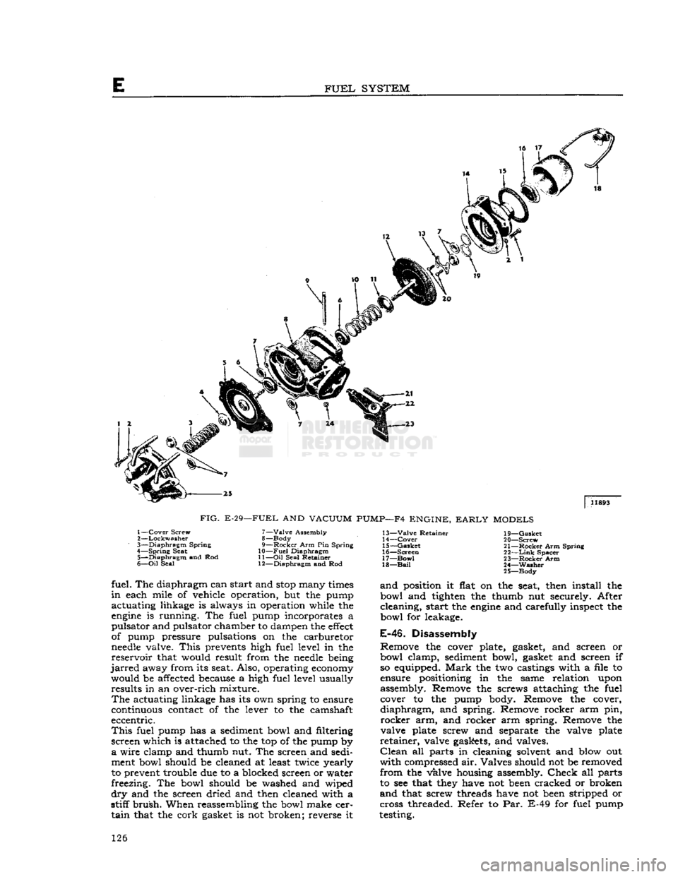
FIG.
E-29—FUEL
AND
VACUUM
PUMP—F4
ENGINE,
EARLY
MODELS
1—
Cover
Screw
2—
Lockwasher
3—
Diaphragm
Spring
4—
Spring
Seat 5—
Diaphragm
and Rod
6—
Oil
Seal 7—
Valve
Assembly
8— Body
9—
Rocker
Arm Pin Spring
10—
Fuel
Diaphragm
11—
Oil
Seal Retainer
12—
Diaphragm
and Rod 13—
Valve
Retainer
14—
Cover
15—
Gasket
16—
Screen
17—
Bow!
18—
Bail
19—
Gasket
20—
Screw
21—
Rocker
Arm Spring
22—
Link
Spacer
23—
Rocker
Arm
24—
Washer
25—
Body
fuel. The diaphragm can start and
stop
many
times
in
each mile of vehicle operation, but the pump
actuating lihkage is always in operation while the
engine
is running. The fuel pump incorporates a
pulsator and pulsator chamber to dampen the
effect
of pump pressure pulsations on the carburetor
needle
valve.
This
prevents high fuel level in the
reservoir
that would result from the
needle
being
jarred
away from its seat. Also, operating
economy
would be affected because a high fuel level usually results in an over-rich mixture.
The
actuating linkage has its own spring to ensure
continuous contact of the lever to the camshaft
eccentric.
This
fuel pump has a sediment bowl and filtering
screen which is attached to the top of the pump by
a
wire clamp and thumb nut. The screen and sedi
ment bowl should be cleaned at least twice yearly
to prevent trouble due to a blocked screen or water
freezing. The bowl should be washed and wiped
dry
and the screen dried and then cleaned with a
stiff
brush.
When reassembling the bowl make cer
tain
that the cork gasket is not broken; reverse it
and
position it flat on the seat, then install the
bowl and tighten the thumb nut securely. After
cleaning, start the
engine
and carefully inspect the
bowl for leakage.
E-46.
Disassembly
Remove the cover plate, gasket, and screen or
bowl clamp, sediment bowl, gasket and screen if so equipped.
Mark
the two castings with a file to
ensure positioning in the same relation upon
assembly. Remove the screws attaching the fuel cover to the pump body. Remove the cover,
diaphragm,
and spring. Remove rocker arm pin,
rocker
arm, and rocker arm spring. Remove the
valve plate screw and separate the valve plate
retainer,
valve gaskets, and valves.
Clean
all parts in cleaning solvent and blow out
with
compressed air. Valves should not be removed
from
the valve housing assembly.
Check
all parts
to see that
they
have not
been
cracked or broken
and
that screw threads have not
been
stripped or
cross threaded. Refer to Par. E-49 for fuel pump
testing. 126