compression ratio JEEP CJ 1953 Service Manual
[x] Cancel search | Manufacturer: JEEP, Model Year: 1953, Model line: CJ, Model: JEEP CJ 1953Pages: 376, PDF Size: 19.96 MB
Page 6 of 376
GENERAL
DATA
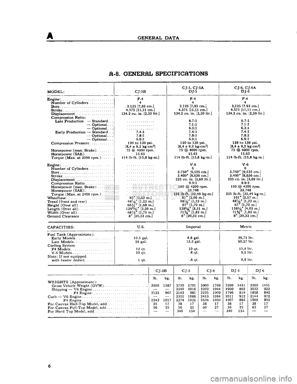
A-8. GENERAL SPECIFICATIONS
MODEL:
CJ-3B
CJ-5,
CJ-5A
DJ-5
CJ-6,
CJ-6A
DJ-6
Engine:.
Number
of
Cylinders
Bore.
.
Stroke.
Displacement
Compression
Ratio:
Late
Production —
Standard
—
Optional.
—
Optional.
Early
Production —
Standard
—
Optional.
—
Optional.
Compression
Pressure
Horsepower
(max.
Brake)
Horsepower
(SAE)
Torque
(Max. at 2000
rpm.).
. . .
Engine:
Number
of
Cylinders
Bore
Stroke
Displacement
Compression
Ratio
Horsepower
(max.
Brake).
Horsepower
(SAE)
Torque
(Max. at 2400
rpm.).
. . .
Wheelbase
Tread
(front and
rear)
,
Height
(Over
all)
Length
(Over
all).
Width
(Over
all)
Ground
Clearance
F-4
4
3.125 [7,93 cm.]
4.375 [11,11 cm.]
134.2 cu. in. [2,20 ltr.]
7.4:1 7.8:1
6.9:1
120 to 130 psi.
[8,4 a 9,2 kg-cm2] 75 <§ 4000 rpm.
15.63
114 lb-ft. [15,8 kg-m.]
80"
[2,03 m.]
487-'f6/' [1,23 m.|
6634" [1,68 m.j
129%"
[3,30 m.]
68%"
[1,75 m.] 8" [20,32 cm.]
F-4
4
3.125 [7,93 cm.]
4.375 [11,11 cm.]
134.2 cu. in. [2,20 ltr.]
6.7:1 7.1:1
6.3:1 7.4:1
7.8:1
6.9:1
120 to 130 psi.
[8,4 a 9,2 kg-cm2] 75 @ 4000 rpm. 15.63
114 lb-ft. [15,8 kg-m.]
V-6
6
3.750" [9,525 cm.]
3.400" [8,636 cm.]
225 cu.
in.
[3,69 ltr.] 9.0:1
160 @ 4200 rpm. 33.748
235 lb-ft. [32,49 kg-m.]
81"
[2,06 m.]
48K6"
[1,23 m.]
67"
[1,70 m.]
138%"
[3,51 m.]
71%"
[1,82 m.] 8" [20,32 cm.]
F-4
4
3,125 [7.93 cm.]
4.375 [11,11 cm.]
134.2 cu. in. [2,20 ltr.]
6.7:1 7.1:1
6.3:1 7.4:1
7.8:1
6.9:1
120 to 130 psi.
[8,4 a 9,2 kg-cm2] 75 @ 4000 rpm.
15.63
114 lb-ft. [15,8 kg-m.]
V-6
6
3.750" [9,525 cm.]
3.400" [8,636 cm.]
225 cu. in. [3,69 ltr.] 9.0:1
160 @, 4200 rpm. 33 748
235 lb-ft. [32,49 kg-m.]
101"
[2,57 m.]
48^6* ]1,23 m.]
67"
[1,70 m.]
1583/4" [4,02 m.]
71%"
[1,82 m.] 8" [20,32 cm.]
CAPACITIES:
U.S.
Imperial
Metric
Fuel
Tank
(Approximate):
Early
Models
Late
Models
Cooling
System
F4
Models
V-6
Models
Note: If not equipped
with
heater deduct 10.5 gal.
16 gal.
12 qt.
10 qt.
1 qt. 8.8 gal.
13.3 gal.
10 qt. 8 qt.
.8 qt. 39,75 ltr.
60,57 ltr.
11,4 ltr. 9,5 ltr.
0,9 ltr.
CJ-
3B
CJ-5
CJ-6
DJ-5
DJ
-6
lb. kg. lb.
kg. lb.
kg. lb.
kg. lb.
kg.
WEIGHTS
(Approximate):
Gross
Vehicle
Weight
(GVW).
3500
1587 3750 1701 3900 1769 3200 1451 3200 1451
Shipping
— V6
Engine
—
'—
2240 1016 2302 1044 1900 862 2033 922
F4
Engine
2132
967 2163
981 2225
1009 1796 814 1858 842
Curb
— V6
Engine
— —
2351 1066 2413 1094 2011 912 2144 972
F4
Engine
2243
1017 2274 1031
2336 1060 1907 865 1969 893
For
Canvas
Half-Top
Model, add 35
17 38
17 38
17 38
17 38 17
For
Canvas
Full-Top
Model, add 56
25 56 25 60 27 56 25 60 27
For
Hard
Top Model, add
~~
340
154 340 154 6
Page 19 of 376
Jeep*
UNIVERSAL SERIES SERVICE
MANUAL
c
TUNE-UP
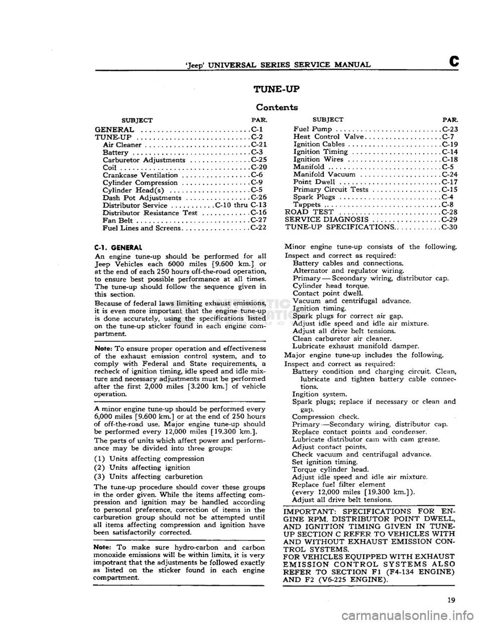
Contents
SUBJECT
PAR.
GENERAL
C-l
TUNE-UP
.C-2
Air
Cleaner
C-21
Battery
. C-3
Carburetor
Adjustments
C-2 5
Coil
C-20
Crankcase
Ventilation C-6
Cylinder
Compression C-9
Cylinder
Head(s) .C-5
Dash
Pot Adjustments .C-26
Distributor
Service C-10
thru
C-13
Distributor
Resistance Test C-l6
Fan
Belt
C-2 7
Fuel
Lines
and Screens
C-2
2
C-l.
GENERAL
An
engine tune-up should be performed for all
Jeep Vehicles each 6000 miles [9.600 km.] or at the end of each 250 hours off-the-road operation,
to ensure best possible performance at all times.
The
tune-up should follow the sequence given in
this section.
Because of federal laws limiting exhaust emissions,
it
is even more important that the engine tune-up is
done
accurately, using the specifications listed
on the tune-up sticker found in each engine com
partment.
Note;
To ensure proper operation and effectiveness
of the exhaust emission control system, and to
comply with
Federal
and State requirements, a
recheck
of ignition timing, idle speed and idle mix
ture
and necessary adjustments must be performed
after the first
2,000
miles [3.200 km.] of vehicle
operation.
A
minor engine tune-up should be performed every
6,000
miles [9.600 km.] or at the end of 250 hours
of off-the-road use.
Major
engine tune-up should
be performed every 12,000 miles [19.300 km.].
The
parts of units which affect power and perform
ance may be divided into three groups:
(1) Units affecting compression
(2) Units affecting ignition
(3) Units affecting carburetion
The
tune-up procedure should cover
these
groups
in
the order given. While the items affecting com
pression and ignition may be handled according
to personal preference, correction of items in the
carburetion
group should not be attempted until
all
items affecting compression and ignition have
been satisfactorily corrected.
Note:
To make sure hydro-carbon and carbon
monoxide emissions
will
be within limits, it is very
impotrant
that the adjustments be followed exactly
as listed on the sticker found in each engine compartment.
SUBJECT
PAR.
Fuel
Pump . . C-23
Heat
Control
Valve C-7
Ignition
Cables C-19
Ignition
Timing
. C-14
Ignition
Wires C-l8
Manifold
C-5
Manifold
Vacuum C-24
Point
Dwell C-17
Primary
Circuit
Tests
.................
C-15
Spark
Plugs C-4
Tappets
C-8
ROAD TEST C-2
8
SERVICE
DIAGNOSIS
. : C-29
TUNE-UP SPECIFICATIONS..
C-30
Minor
engine tune-up consists of the following.
Inspect
and correct as required:
Battery
cables and connections.
Alternator
and regulator wiring.
Primary
— Secondary wiring, distributor cap.
Cylinder
head torque.
Contact
point dwell.
Vacuum
and centrifugal advance.
Ignition
timing.
Spark
plugs for correct air gap.
Adjust
idle speed and idle air mixture.
Adjust
all drive belt tensions.
Clean
carburetor air cleaner.
Lubricate
exhaust manifold damper.
Major
engine tune-up includes the following.
Inspect
and correct as required:
Battery
condition and charging
circuit.
Clean,
lubricate
and tighten battery cable connec
tions.
Ingition
system.
Spark
plugs; replace if necessary or clean and gap.
Compression
check.
Primary—Secondary
wiring, distributor cap.
Replace
contact points and condenser.
Lubricate
distributor cam with cam grease.
Adjust
contact points.
Check
vacuum and centrifugal advance. Set ignition timing.
Torque
cylinder head.
Adjust
idle speed and idle air mixture.
Replace
fuel filter element (every 12,000 miles [19.300
km.]).
Adjust
all drive belt tensions.
IMPORTANT: SPECIFICATIONS
FOR EN-
GINE
RPM.
DISTRIBUTOR POINT DWELL,
AND IGNITION TIMING GIVEN
IN
TUNE- UP SECTION
C
REFER
TO
VEHICLES
WITH
AND WITHOUT EXHAUST EMISSION CON
TROL
SYSTEMS.
FOR
VEHICLES
EQUIPPED WITH EXHAUST
EMISSION CONTROL SYSTEMS ALSO
REFER
TO
SECTION
Fl (F4-134
ENGINE)
AND
F2 (V6-225
ENGINE).
19
Page 24 of 376
c
TUNE-UP
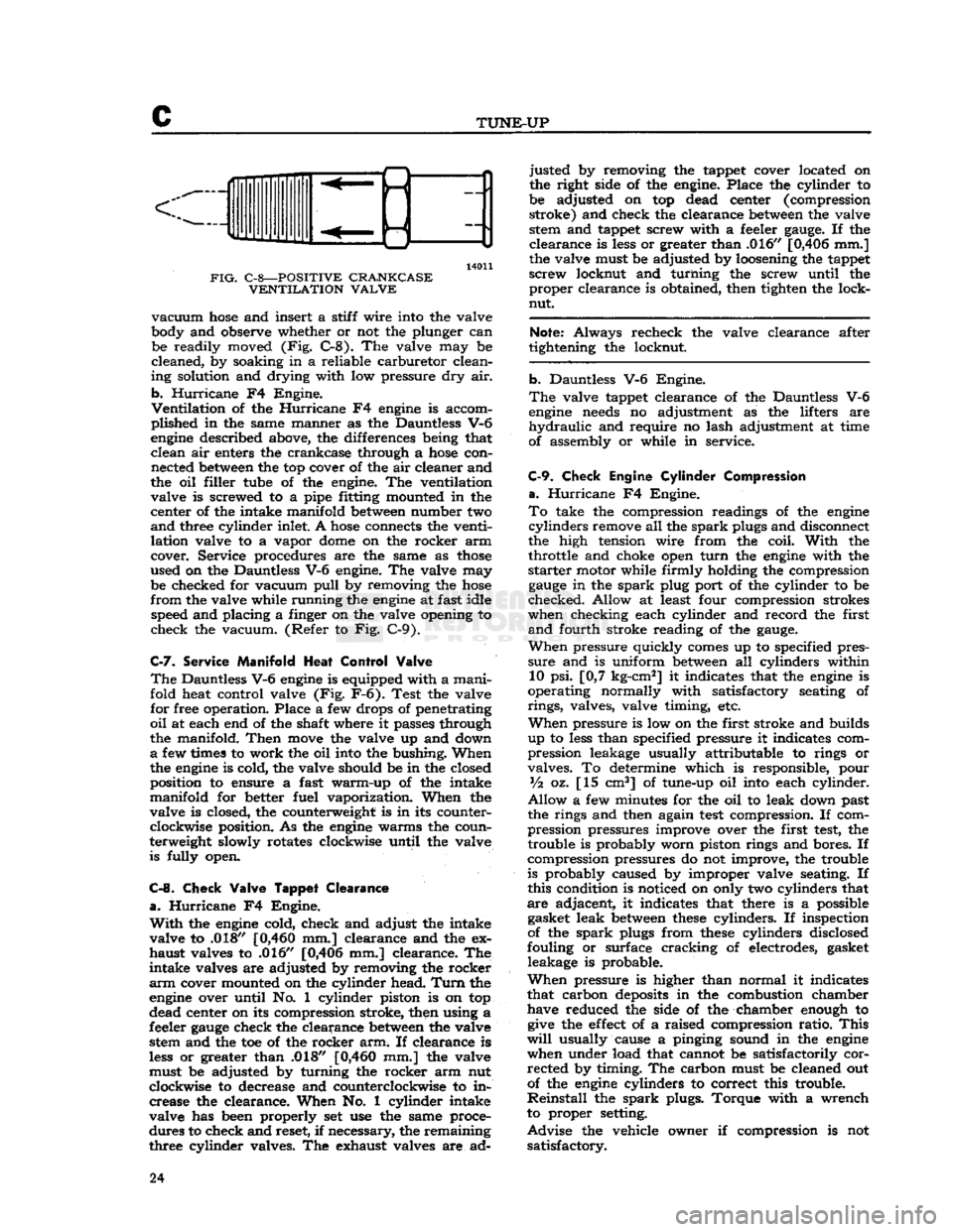
14011
FIG.
C-8—POSITIVE CRANKCASE VENTILATION VALVE
vacuum
hose
and insert a stiff wire into the valve
body and observe whether or not the plunger can be readily moved (Fig. C-8). The valve may be
cleaned, by soaking in a reliable carburetor clean
ing solution and drying with low pressure dry air.
b.
Hurricane
F4 Engine.
Ventilation
of the
Hurricane
F4
engine
is accom
plished in the same manner as the Dauntless V-6
engine
described above, the differences being that clean air enters the crankcase through a
hose
con nected
between
the top cover of the air cleaner and
the oil filler tube of the engine. The ventilation valve is screwed to a pipe fitting mounted in the
center of the intake manifold
between
number two
and
three cylinder inlet. A
hose
connects the venti
lation valve to a vapor
dome
on the rocker arm
cover. Service procedures are the same as
those
used on the Dauntless V-6 engine. The valve may be checked for vacuum
pull
by removing the
hose
from
the valve while running the
engine
at fast idle speed and placing a finger on the valve opening to
check the vacuum. (Refer to Fig. C-9).
C-7.
Service
Manifold
Heat
Control
Valve
The
Dauntless V-6
engine
is equipped with a manifold heat control valve (Fig. F-6). Test the valve
for free operation. Place a few drops of penetrating
oil
at each end of the shaft where it passes through
the manifold.
Then
move
the valve up and down
a
few times to work the oil into the bushing. When
the
engine
is cold, the valve should be in the closed
position to ensure a fast warm-up of the intake
manifold for better fuel vaporization. When the
valve is closed, the counterweight is in its counter clockwise position. As the
engine
warms the coun
terweight slowly rotates clockwise until the valve is fully open.
C-8.
Check
Valve
Tappet
Clearance
a.
Hurricane
F4 Engine.
With
the
engine
cold, check and adjust the intake
valve to .018"
[0,460
mm.] clearance and the ex
haust valves to .016" [0,406 mm.] clearance. The
intake valves are adjusted by removing the rocker
arm
cover mounted on the cylinder head.
Turn
the
engine
over until No. 1 cylinder piston is on top
dead center on its compression stroke, then using a
feeler
gauge
check the clearance
between
the valve stem and the toe of the rocker arm. If clearance is
less
or greater than .018"
[0,460
mm.] the valve
must be adjusted by turning the rocker arm nut
clockwise to decrease and counterclockwise to in crease the clearance. When No. 1 cylinder intake
valve has been properly set use the same proce
dures to check and reset, if necessary, the remaining
three cylinder valves. The exhaust valves are ad justed by removing the tappet cover located on
the right side of the engine. Place the cylinder to
be adjusted on top dead center (compression stroke) and check the clearance
between
the valve stem and tappet screw with a feeler
gauge.
If the
clearance is
less
or greater than .016" [0,406 mm.]
the valve must be adjusted by loosening the tappet
screw locknut and turning the screw until the proper clearance is obtained, then tighten the lock-
nut.
Note:
Always recheck the valve clearance after
tightening the locknut.
b. Dauntless V-6 Engine.
The
valve tappet clearance of the Dauntless V-6
engine
needs
no adjustment as the lifters are
hydraulic
and require no lash adjustment at time
of assembly or while in service.
C-9.
Check
Engine
Cylinder
Compression
a.
Hurricane
F4 Engine.
To
take the compression readings of the
engine
cylinders
remove all the
spark
plugs and disconnect
the high tension wire from the coil.
With
the throttle and choke open
turn
the
engine
with the
starter
motor while firmly holding the compression
gauge
in the
spark
plug port of the cylinder to be
checked. Allow at least four compression strokes
when checking each cylinder and record the first
and
fourth stroke reading of the
gauge.
When
pressure quickly
comes
up to specified pres
sure
and is uniform
between
all cylinders within 10 psi. [0,7 kg-cm2] it indicates that the
engine
is
operating normally with satisfactory seating of
rings,
valves, valve timing, etc.
When
pressure is low on the first stroke and builds
up to
less
than specified pressure it indicates com
pression leakage usually attributable to rings or
valves. To determine which is responsible, pour
Vz
oz. [15 cm3] of tune-up oil into each cylinder.
Allow
a few minutes for the oil to leak down past
the rings and then again
test
compression. If com
pression pressures improve over the first
test,
the trouble is probably worn piston rings and bores. If
compression pressures do not improve, the trouble
is probably caused by improper valve seating. If
this condition is noticed on only two cylinders that
are adjacent, it indicates that there is a possible gasket leak
between
these
cylinders. If inspection
of the
spark
plugs from
these
cylinders disclosed
fouling or surface cracking of electrodes, gasket leakage is probable.
When
pressure is higher than normal it indicates
that carbon
deposits
in the combustion chamber have reduced the side of the chamber enough to
give
the
effect
of a raised compression ratio.
This
will
usually cause a pinging sound in the
engine
when under load that cannot be satisfactorily corrected by timing. The carbon must be cleaned out
of the
engine
cylinders to correct this trouble.
Reinstall
the
spark
plugs. Torque with a wrench
to proper setting.
Advise
the vehicle owner if compression is not satisfactory. 24
Page 28 of 376
c
TUNE-UP
C-13. Replacement and Adjustment of
Delco
Distributor Point Set
When
inspection of the contact points show re placement to be advisable, the following procedure
should be used. See Fig. C-13.
Note:
The service replacement contact point set
has the breaker spring tension and point alignment
adjusted at the factory.
Removal
of
Contact Point
Set
a.
Remove distributor cap by inserting a screw
driver
in upper slotted end of cap retainers,
press
down and turn 90° counterclockwise. Push distri
butor cap aside and remove rotor. Disconnect the condenser and primary leads from their terminal
by loosening the retaining screw. If there is no
retaining
screw, simply slip leads out.
b. Loosen two screws and lock
washers
which hold
the contact point set in place. Then remove point
set.
Installation
of
Contact Point
Set.
a.
Slide contact point set over
boss
on breaker
plate and under the two screw heads. Tighten two
screws and lock washers.
b.
Install
condenser and primary leads.
Note:
Leads must be properly positioned so they
will
not
come
in contact with
bottom
of weight
base or rotor.
c.
If
engine
does
not start readily, position contact
arm
rubbing block on peak of cam lobe, insert
V%"
[3,86 mm.] Allen wrench in adjusting screw and
turn
screw in (clockwise) until contact points
just
close. Then back screw out (counterclockwise)
V2
turn
(180°)
to obtain a point gap of approxi
mately .016" [0,406 mm.] for a preliminary setting.
Adjustment
of
Contact Points
—
Engine Running
Note:
When adjusting contact point dwell angle,
always follow the instructions which
come
with the
dwell
meter.
a.
Connect dwell tester leads: red to distributor
side of coil, black to ground.
b. Turn
selector switch to position for
6-lobe
cam.
Turn
ignition switch on.
c.
Start engine.
Lift
adjustment window and insert
Vs"
[3,86 mm.] Allen wrench in adjusting screw.
Set dwell angle at 30 degrees. See Fig. C-14.
d.
After adjusting dwell angle, always check
ignition timing.
C-14.
Check
Ignition
Timing
a.
Hurricane F4 Engine.
If
a neon timing light is available, use it to check
igntion timing following the instructions of the
timing light manufacturer.
In
the absence of a timing light, remove No. 1
spark
plug and turn the
engine
over until No. 1
piston is on compression stroke as indicated by
air
being forced from No. 1 spark plug opening.
Turn
the
engine
slowly until the specified
degree
mark
on the timing gear cover is in alignment with
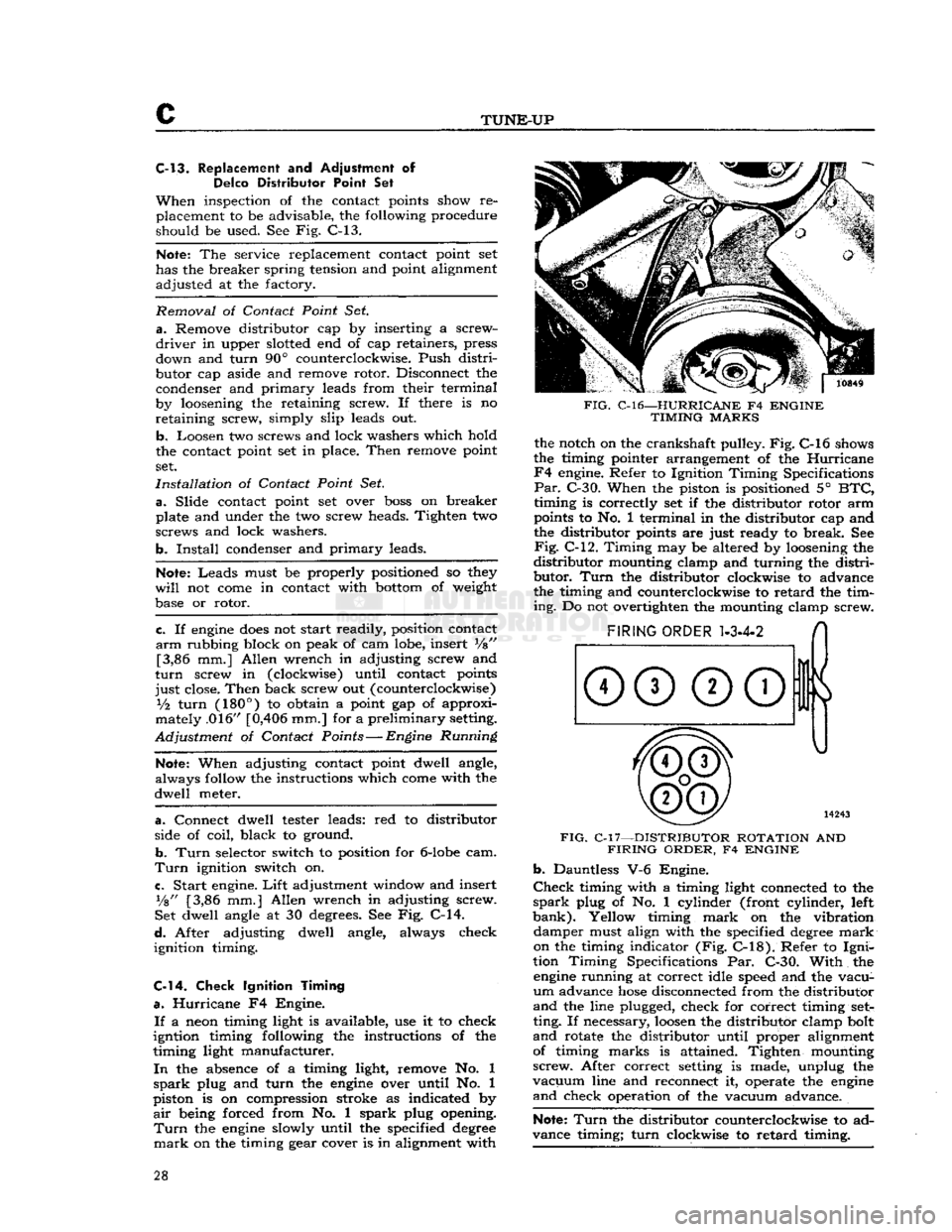
FIG.
C-l6—HURRICANE
F4
ENGINE
TIMING
MARKS
the notch on the crankshaft pulley. Fig. C-l6 shows
the timing pointer arrangement of the Hurricane
F4
engine. Refer to Ignition Timing Specifications
Par.
C-30. When the piston is positioned 5°
BTC,
timing is correctly set if the distributor rotor arm
points to No. 1 terminal in the distributor cap and
the distributor points are just ready to break. See
Fig.
C-12. Timing may be altered by loosening the
distributor
mounting clamp and turning the distri
butor.
Turn
the distributor clockwise to advance
the timing and counterclockwise to retard the tim
ing.
Do not overtighten the mounting clamp screw.
FIG.
C-l7—DISTRIBUTOR ROTATION
AND
FIRING
ORDER,
F4
ENGINE b.
Dauntless V-6 Engine.
Check
timing with a timing light connected to the
spark
plug of No. 1 cylinder (front cylinder, left
bank).
Yellow timing
mark
on the vibration damper must align with the specified
degree
mark
on the timing indicator (Fig.
C-18).
Refer to
Igni
tion Timing Specifications Par. C-30. With the
engine
running at correct idle speed and the vacu
um
advance
hose
disconnected from the distributor
and
the line plugged, check for correct timing
set
ting. If necessary,
loosen
the distributor clamp bolt
and
rotate the distributor until proper alignment of timing marks is attained. Tighten mounting
screw.
After correct setting is made, unplug the
vacuum
line and reconnect it, operate the
engine
and
check operation of the vacuum advance.
Note:
Turn
the distributor counterclockwise to ad
vance timing; turn clockwise to retard timing. 28
Page 35 of 376
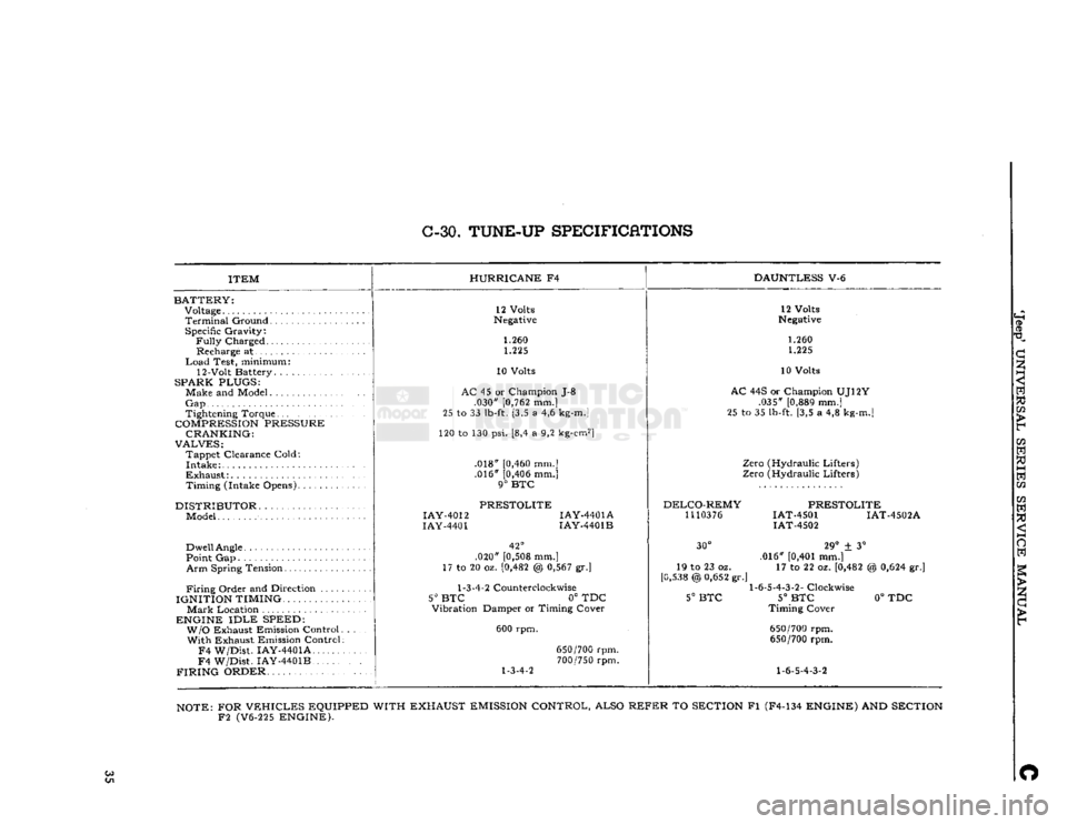
C-30.
TUNE-UP
SPECIFICATIONS
ITEM
BATTERY:
Voltage
Terminal
Ground Specific Gravity:
Fully
Charged Recharge at
Load
Test, minimum:
12-Volt Battery. .
SPARK PLUGS:
Make and Model
Gap
Tightening Torque
COMPRESSION
PRESSURE CRANKING:
VALVES:
Tappet Clearance Cold:
Intake
Exhaust:
Timing (Intake Opens)
DISTRIBUTOR
Model
Dwell
Angle
Point Gap
Arm
Spring Tension
Firing
Order and Direction ....
IGNITION TIMING.
Mark
Location
ENGINE
IDLE
SPEED: W/O
Exhaust Emission Control With Exhaust Emission Control
F4
W/Dist. IAY-4401A
F4
W/Dist. IAY-4401B
FIRING
ORDER HURRICANE
F4
DAUNTLESS
V-6
12 Volts
Negative
1.260 1.225
10 Volts
AC
45 or Champion J-8 .030"
[0,762
mm.]
25 to 33
lb-ft.
[3,5 a 4,6
kg-m.]
120 to 130 psi. [8,4 a 9,2
kg-cm2]
.018"
[0,460
mm.] .016"
[0,406
mm.]
9°
BTC
PRESTOLITE
IAY-4012
IAY-4401A
IAY-4401
IAY-4401B
42°
.020"
[0,508
mm.]
17 to 20 oz.
[0,482
@
0,567
gr.]
1-3-4-2
Counterclockwise
5° BTC
0° TDC
Vibration Damper or Timing Cover
600 rpm.
1-3-4-2
650/700
rpm.
700/750
rpm. 12 Volts
Negative
1.260 1.225
10 Volts
AC
44S or Champion UJ12Y .035"
[0,889
mm.]
25 to 35
lb-ft.
[3,5 a 4,8
kg-m.]
Zero (Hydraulic Lifters)
Zero (Hydraulic Lifters)
DELCO-REMY
1110376
PRESTOLITE
IAT-4501 IAT-4502A
IAT-4502
30°
19 to 23 oz.
[0,538
@
0,652
gr.'
5°
BTC
29°
± 3°
.016"
[0,401
mm.] 17 to 22 oz.
[0,482
1-6-5-4-3-2-
Clockwise
5°
BTC
Timing Cover
650/700
rpm.
650/700
rpm.
1-6-5-4-3-2
%
0,624
gr.]
0°
TDC
NOTE:
FOR
VEHICLES
EQUIPPED WITH EXHAUST
EMISSION
CONTROL, ALSO
REFER
TO
SECTION
Fl (F4-134
ENGINE)
AND
SECTION
F2
(V6-225
ENGINE).
Co O
Page 38 of 376
HURRICANE
F4
ENGINE
D-1.
GENERAL
This
section describes service and repair of the
F4
engine. The
engine
code
number shown in Fig.
A-3
is provided to identify the four cylinder engine.
The
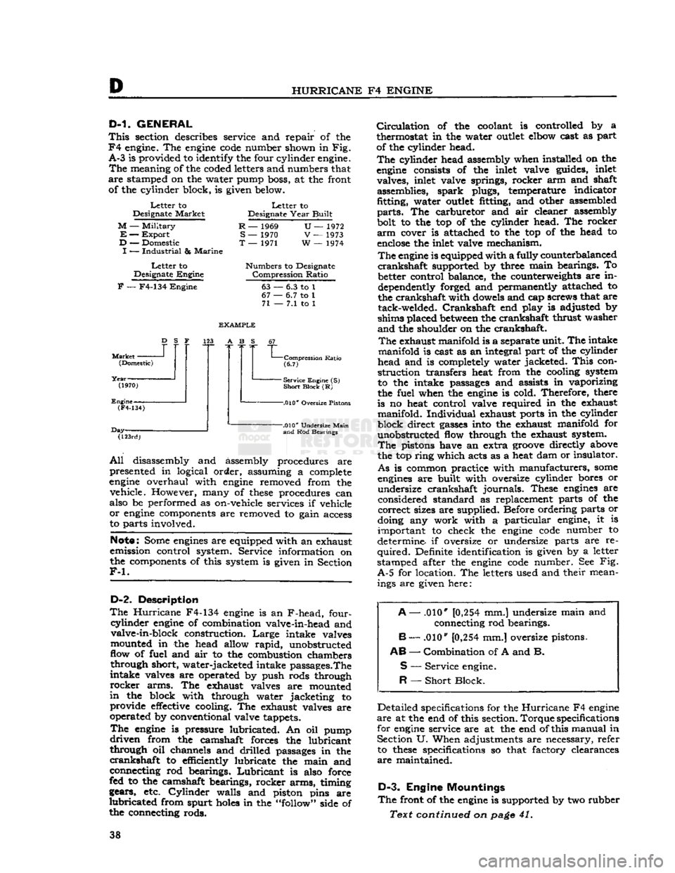
meaning of the coded letters and numbers that
are
stamped on the water pump boss, at the front of the cylinder block, is given below.
Letter
to
Designate
Market
M
—
Military
E
—
Export
D
— Domestic
I
—
Industrial
&
Marine
Letter
to
Designate
Engine
Letter
to
Designate
Year
Built
R
— 1969
S
— 1970
T
— 1971
U—
1972
V
— 1973
W
— 1974
Numbers
to Designate
Compression
Ratio
F
— F4-134
Engine
63
67
•
71
-
6.3 to 1
•
6.7 to 1
-
7.1 to 1
Market
-
D
S F
(Domestic)
(1970)
Engine-
EXAMPLE
123 A B S
(F4-134)
Day- "L
Compression
Ratio
(6.7)
-
Service Engine (S)
Short
Block
(R)
-.010*
Oversize Pistons
(123rd)
-.010*
Undersize
Main
and
Rod Bearings
All
disassembly and assembly procedures are
presented in logical order, assuming a complete
engine
overhaul with
engine
removed from the vehicle. However, many of
these
procedures can
also be performed as on-vehicle services if vehicle
or
engine
components are removed to gain access
to parts involved.
Note:
Some
engines
are equipped with an exhaust
emission control system. Service information on
the components of this system is given in Section
F-l.
D-2.
Description
The
Hurricane
F4-134
engine
is an F-head, four-
cyiinder
engine
of combination valve-in-head and valve-in-block construction.
Large
intake valves
mounted in the head allow
rapid,
unobstructed
flow of fuel and air to the combustion chambers through short, water-jacketed intake passages.The
intake valves are operated by push rods through
rocker
arms. The exhaust valves are mounted
in
the block with through water jacketing to provide
effective
cooling. The exhaust valves are
operated by conventional valve tappets.
The
engine
is pressure lubricated. An oil pump
driven
from the camshaft forces the lubricant
through oil channels and drilled passages in the
crankshaft
to efficiently lubricate the main and
connecting rod bearings.
Lubricant
is also force
fed to the camshaft bearings, rocker arms, timing
gears, etc.
Cylinder
walls and piston pins are
lubricated
from spurt
holes
in the "follow" side of
the connecting rods.
Circulation
of the coolant is controlled by a
thermostat in the water
outlet
elbow cast as part
of the cylinder head.
The
cylinder head assembly when installed on the
engine
consists of the inlet valve guides, inlet valves, inlet valve springs, rocker arm and shaft assemblies, spark plugs, temperature indicator
fitting, water
outlet
fitting, and other assembled
parts.
The carburetor and air cleaner assembly
bolt to the top of the cylinder head. The rocker
arm
cover is attached to the top of the head to
enclose
the inlet valve mechanism.
The
engine
is equipped with a fully counterbalanced
crankshaft
supported by three main bearings. To better control balance, the counterweights are in
dependently forged and permanently attached to
the crankshaft with dowels and cap screws that are tack-welded.
Crankshaft
end play is adjusted by
shims placed
between
the crankshaft thrust washer
and
the shoulder on the crankshaft.
The
exhaust manifold is a separate unit. The intake
manifold is cast as an integral part of the cylinder
head and is completely water jacketed.
This
con
struction transfers heat from the cooling system
to the intake passages and assists in vaporizing
the fuel when the
engine
is cold. Therefore, there
is no heat control valve required in the exhaust manifold. Individual exhaust ports in the cylinder
block direct
gasses
into the exhaust manifold for unobstructed flow through the exhaust system.
The
pistons have an extra
groove
directly above
the top ring which acts as a heat dam or insulator.
As
is common practice with manufacturers,
some
engines
are built with oversize cylinder bores or undersize crankshaft journals. These
engines
are
considered standard as replacement parts of the
correct
sizes are supplied. Before ordering parts or
doing any work with a particular engine, it is important to check the
engine
code
number to
determine if oversize or undersize parts are re
quired.
Definite identification is given by a letter
stamped after the
engine
code
number. See Fig.
A-5
for location. The letters used and their mean ings are given here:
A
— .010*
[0,254
mm.] undersize main and
connecting rod bearings.
B
— .010"
[0,254
mm.] oversize pistons.
AB
—
Combination
of A and B.
S
—
Service
engine.
R
—
Short
Block.
Detailed specifications for the
Hurricane
F4
engine
are
at the end of this section.
Torque
specifications
for
engine
service are at the end of this manual in Section U. When adjustments are necessary, refer to
these
specifications so that factory clearances
are
maintained.
D-3.
Engine Mountings
The
front of the
engine
is supported by two rubber
Text continued on
page
41. 38
Page 47 of 376
'Jeep*
UNIVERSAL
SERIES SERVICE
MANUAL
D
straight
in the hole, then tap the dowel lightly
with
a hammer until it
bottoms.
d.
When installing bearing eaps, be sure to tighten
the
bolts
evenly in each cap to
pull
it into place
without bending the
dowels
or distorting the
bearing
cap.
e. Other parts of the block which require inspec tion
and
possible
repair,
but which are directly
related
to other
engine
components (such as tappets, pistons, camshaft, valves, crankshaft, and
oil
pump) are covered later in this section.
D-35.
Cylinder
Bores
The
cylinder bores may be reconditioned by honing
or
reboring. Use oil-soaked rags to protect
crank
shaft
journals
and other
engine
parts from abrasive
dust during all reconditioning operations.
Both
honing and reboring of the cylinders must be
done
carefully to fit the pistons and to obtain
specified clearances. If reboring of the cylinder bores is not required but the walls are glazed, use
a
finishing
hone
to remove the glaze. Reboring the cylinders must not be attempted unless ade
quate facilities and experienced service technicians
are
available. The amount of material to be removed is determined from the original diameter
of the cylinder bores (3.125" to 3.127") [79,375 a
79,426
mm.] plus the amount of oversize in diameter
of the oversize pistons to be fitted. Pistons are
available
in the following oversizes.
.010"
[0,254
mm.] .030" [0,762 mm.] .020" [0,508 mm.] .040" [1,016 mm.}
The
largest cylinder bore
will
determine the over
size to which all cylinders must be rebored, since the size and weight of all pistons must be uniform
to maintain proper
engine
balance. The maximum rebore should not exceed .040" [1,016 mm.] from
standard.
Measure
the cylinder diameters by making mea
surements both parallel to and at right angles to
crankshaft
over entire piston travel and at
bottom
of cylinder. Proceed as follows:
a.
If bores are scored; if out-of-round
exceeds
.005
"
[0,127 mm.]; if diameters differ more than .005";
or
if taper
exceeds
.005
"
on diameter, it is generally
recommended that cylinders be reconditioned by
reboring
and honing to the next oversize using new
pistons of the proper size.
Note:
If reboring is performed, allow .0015"
[0,0381
mm.] for final honing.
All
cylinder bore diameters must be within .002
"
[0,0508
mm.] after reconditioning.
b.
If bore measurements are within the above
limits,
but indicate hollows or waviness, cylinders should be honed with 250 grit
stone
hone. Pump
hone
up and down in cylinder while it is rotating
to produce a satin-finish, diamond cross-hatched
pattern
approximately 30° with horizontal. Hone
only enough to correct waviness.
c. If cylinder bore correction is unnecessary, break the glaze on cylinder walls with a 250 grit
stone
hone
or with a suitable deglazing tool. Operate the
hone
or deglazer to obtain diamond cross-hatched
pattern
previously mentioned.
d.
Regardless of type of correction on cylinder
walls,
wash out bores thoroughly afterwards and
apply
a light coat of
engine
oil. If cylinders have
been rebored or honed heavily, measure cylinder
diameters again to assure proper selection of piston
size.
D-36.
Pistons, Rings, and Connecting Rods
Pistons are each fitted with three rings, two com pression rings and one oil control
ring.
The pistons have an extra
groove
above the top ring which acts as a heat dam or insulating
groove
to protect
against sealing of the top ring in the ring
groove
with
hard
carbon. The piston pin is secured by the lock screw.
The
pistons and connecting rods were removed from
the
engine
as assemblies. If cylinders were rebored,
new oversized pistons and rings
will
have to be in
stalled.
Disassemble the pistons and rods. Remove the
two compression rings, the oil control
ring,
and the oil control ring expander from each piston. Do not remove the
bolts
from the lower end of the
connecting rods unless the
bolts
are damaged.
Clamp
each connecting rod and piston assembly
in
a padded bench vise and remove the piston pin
lock
screw and lockwasher. Press the piston pin
out of the piston and connecting rod.
Clean
all
carbon,
gum, and lacquer
deposits
from both the
inner
and outer surfaces of each piston, connecting
rod,
and piston pin. Use a ring
groove
cleaner or a
broken
ring filed to a sharp square
edge
to clean
the carbon from the piston ring
grooves
and the
insulator
groove. Use care not to scrape metal from
the sides of the
grooves
or make
burrs
on ring
groove
surfaces. Run a length of wire through the
oil
spray
hole
near the lower end of the connecting
rod
to clear the
hole
of hardened oil
deposits
or
foreign matter.
Carefully
inspect the pistons and
replace
any that are broken or cracked. Replace
pistons if any of the ring lands are chipped, broken,
or
rounded on the
edges;
or if the piston is scored,
scratched,
or burned so seriously that the imperfec
tions cannot be removed with a hand honing
stone
or
crocus cloth.
Replace
the pistons as follows:
a.
After cylinder bores have been carefully checked for out-of-round and taper (Par. D-35), check fit
of each piston to cylinder bore with block and
pistons clean and dry and at approximately 70
°F.
[21°C]
by using Piston Fitting Gauge And Scale
Tool
No. C-690 as shown in Fig. D-7. Use a .003"
[0,0762
mm.] thickness
gauge
%" [19 mm.] wide.
The
piston is fitted upside down in the block to
facilitate the operation. The
gauge
must extend the
full
length of the piston on the thrust side
(opposite
side from slot in piston
skirt).
Scale should register
5
to 10 pounds [2,3 a 4,5 kg.]
pull
to remove the
thickness
gauge
from
between
cylinder
wall
and piston. Excessive
pull
indicates need for a slightly
smaller
piston or additional honing of cylinder. In sufficient
pull
indicates need for fitting a larger piston. 47
Page 67 of 376
'Jeep'
UNIVERSAL
SERIES SERVICE
MANUAL
D
Lubricate
the connecting rod bearing surfaces
generously with
engine
oil and install the bearing
cap with the numbered side matched to the num
bered side of the connecting rod. Torque the nuts
evenly 35 to 45 lb-ft. [4,8 a 6,2 kg-m.]. The con
necting rod cap nuts are locked with stamped nuts.
Used
stamped nuts should be discarded and re
placed with new
ones.
These locking stamped nuts
should be installed with the flat face toward the
connecting rod nut.
Turn
the locking nut finger
tight and then 34
turn
more with a wrench. Refer
to Par. D-36 for detailed information on fitting pistons and rings in the cylinder bores.
D-96.
Install
Crankshaft
Pulley
Align
the keyway in the pulley with the woodruff key installed in the crankshaft. Drive the pulley
onto
the crankshaft and secure it in place with
the crankshaft pulley nut. Insert a block of wood
between
one of the counterweights on the
crank
shaft and the side of the cylinder block to prevent the crankshaft from turning, then tighten the nut.
D-97.
Install
Oil Pan
Before installing the oil pan, make a final internal
inspection particularly making certain that the
inside of the cylinder block is clean. Apply a thin
coat of gasket paste on the oil pan. Place the new
oil
pan gasket in position. Set the oil pan in posi
tion on the cylinder block and install the oil pan.
Torque
the attaching
bolts
12 to 15 lb-ft. [1,7 a 2,1
kg-m.].
Install
the oil pan
drain
plug and gasket
and
tighten the plug securely.
D-98.
Install
Cylinder
Head
Make
certain that the entire top of the cylinder
block
assembly, the lower surface of the cylinder
head,
and the cylinder head gasket are clean. Blow
all
dirt
or carbon out of the blind tapped bolt
holes
in
the cylinder block before the cylinder head and gasket are installed. Using aerosol spray sealer
Part
No. 994757, spray a thincoat on both surfaces
of the head gasket, position the new cylinder head gasket with the crimped
edges
of the gasket metal down (See Fig. D-31).
This
gasket position allows a
positive seal along the narrow surfaces of the
cylin
der
head
between
the combustion chambers and
eliminates the possibility of burning combustion
10102
FIG.
D-41—CYLINDER
HEAD
BOLT
TIGHTENING
SEQUENCE
gases
reaching
an
asbestos
portion of the cylinder
head gasket.
Install
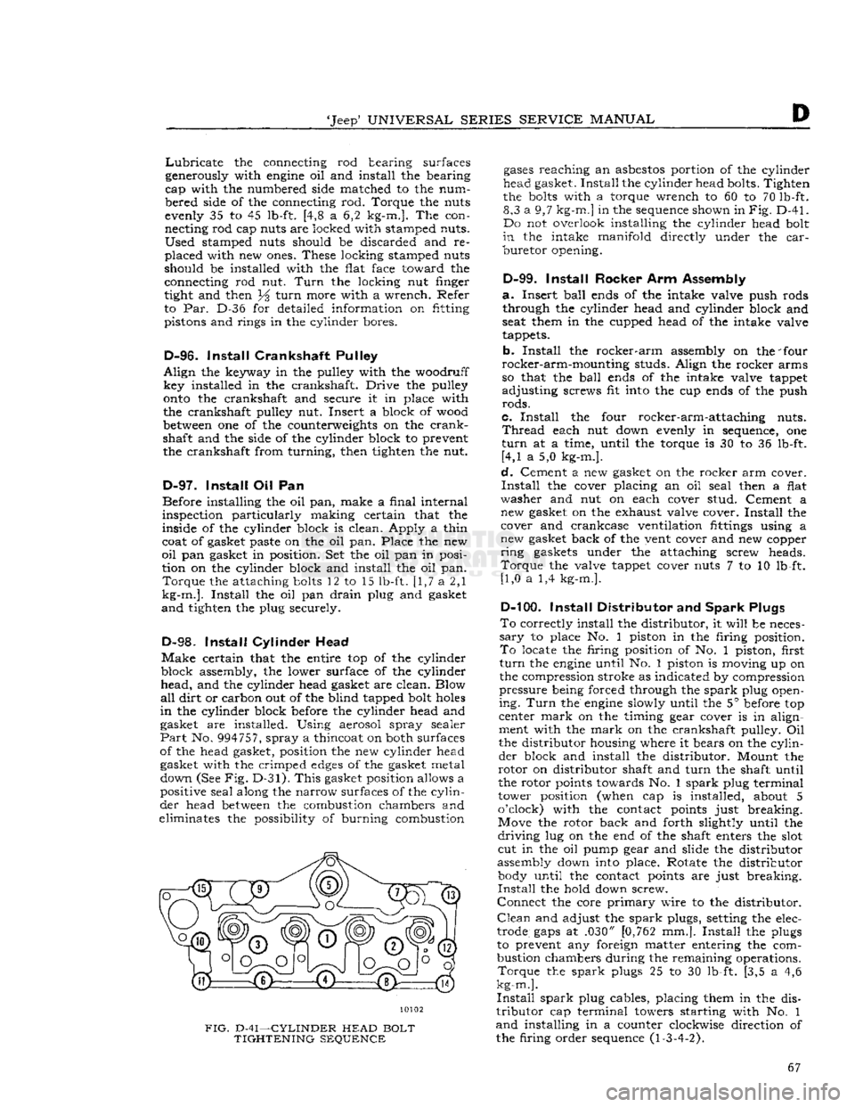
the cylinder head bolts. Tighten
the
bolts
with a torque wrench to 60 to 70 lb-ft. 8,3 a 9,7
kg-m.]
in the sequence shown in
Fig.
D-41.
Do not overlook installing the cylinder head bolt
in
the intake
manifold
directly under the
car
buretor
opening.
D-99.
Install
Rocker Arm Assembly
a.
Insert
ball
ends of the intake valve push rods through the cylinder head and cylinder block and
seat them in the cupped head of the intake valve
tappets.
b.
Install
the
rocker-arm
assembly on the 'four
rocker-arm-mounting
studs. Align the rocker arms
so that the
ball
ends of the intake valve tappet
adjusting
screws fit into the cup ends of the push
rods.
c.
Install
the four rocker-arm-attaching nuts.
Thread
each nut down evenly in sequence, one
turn
at a time, until the torque is 30 to 36 lb-ft. [4,1 a 5,0 kg-m.].
d.
Cement a new gasket on the rocker arm cover.
Install
the cover placing an oil seal then a flat
washer
and nut on each cover stud. Cement a new gasket on the exhaust valve cover.
Install
the cover and crankcase ventilation fittings using a
new gasket back of the vent cover and new copper
ring
gaskets under the attaching screw heads.
Torque
the valve tappet cover nuts 7 to 10 lb-ft. [1,0 a 1,4 kg-m.].
D-100.
Install
Distributor and
Spark
Plugs
To
correctly install the distributor, it
will
be neces
sary
to place No. 1 piston in the firing position.
To
locate the firing position of No. 1 piston, first
turn
the
engine
until No. 1 piston is moving up on
the compression stroke as indicated by compression
pressure
being forced through the
spark
plug open
ing.
Turn
the
engine
slowly until the 5° before top
center
mark
on the timing gear cover is in align
ment with the
mark
on the crankshaft pulley. Oil
the distributor housing where it bears on the
cylin
der
block and install the distributor. Mount the
rotor
on distributor shaft and
turn
the shaft until
the rotor points towards No. 1
spark
plug terminal
tower position (when cap is installed, about 5
o'clock) with the contact points just breaking.
Move the rotor back and forth slightly until the
driving
lug on the end of the shaft enters the slot cut in the oil pump gear and slide the distributor
assembly down into place. Rotate the distributor body until the contact points are just breaking.
Install
the hold down screw.
Connect
the core
primary
wire to the distributor.
Clean
and adjust the
spark
plugs, setting the elec
trode
gaps
at .030" [0,762 mm.].
Install
the plugs
to prevent any foreign matter entering the com
bustion chambers during the remaining operations.
Torque
the
spark
plugs 25 to 30 lb-ft. [3,5 a 4,6
kg-m.].
Install
spark
plug cables, placing them in the dis
tributor
cap terminal towers starting with No. 1
and
installing in a counter clockwise direction of
the firing order sequence (1-3-4-2). 67
Page 71 of 376
'Jeep*
UNIVERSAL
SERIES
SERVICE
MANUAL
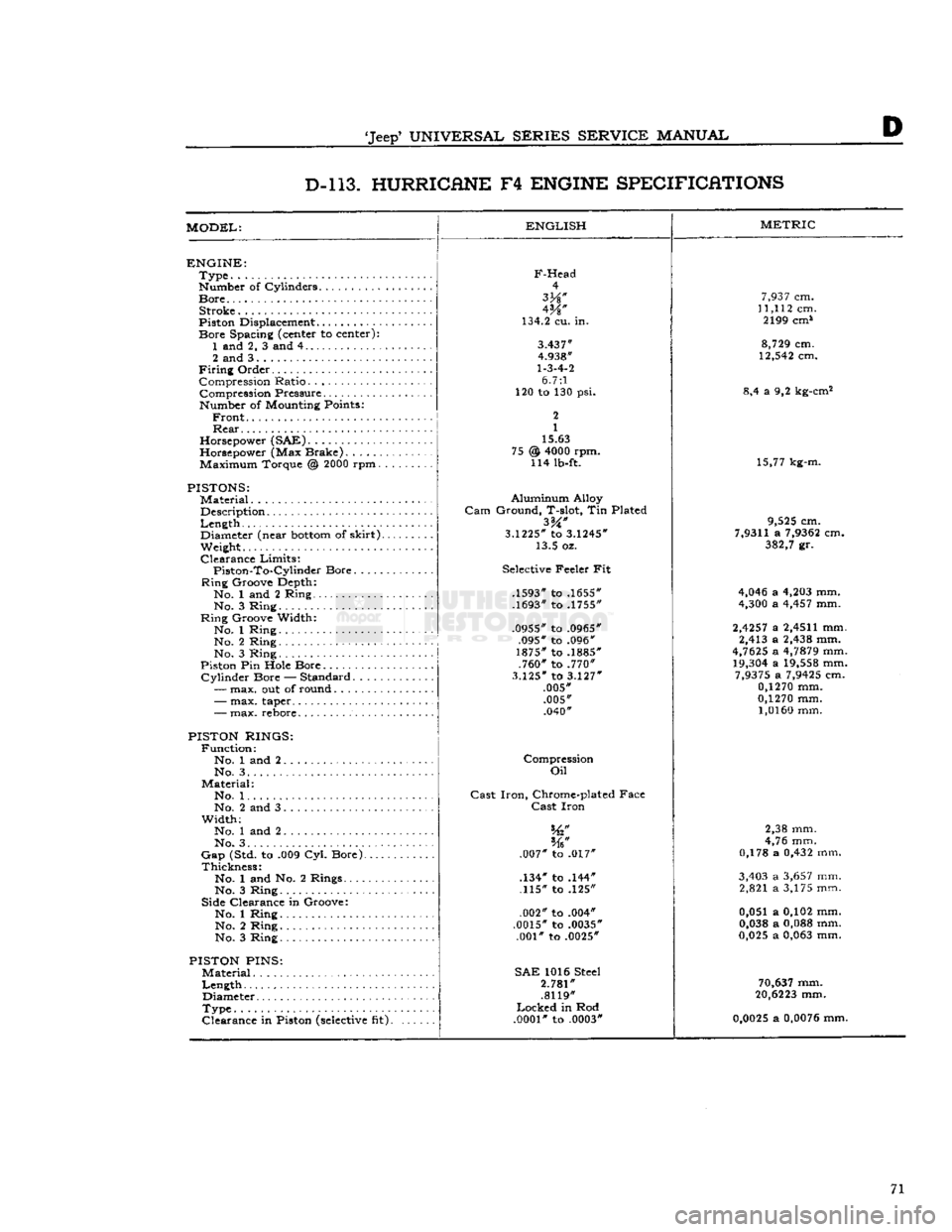
D D-l 13. HURRICANE
F4
ENGINE SPECIFICATIONS
MODEL:
ENGLISH
ENGINE:
Type
Number of Cylinders
Bore
Stroke
Piston Displacement...........
Bore
Spacing (center to center): 1 and 2, 3 and 4
2 and 3
Firing
Order Compression Ratio Compression Pressure... .
Number of Mounting Points:
Front
Rear
Horsepower (SAE)
Horsepower (Max Brake) Maximum Torque @
2000
rpm.
PISTONS:
Material
Description
Length
,.
Diameter (near
bottom
of
skirt).
Weight.
Clearance
Limits:
Piston-To-Cylindcr
Bore
Ring
Groove Depth:
No. 1 and 2 Ring No. 3 Ring
Ring
Groove Width:
No. 1 Ring No. 2 Ring
No. 3 Ring
Piston Pin Hole Bore
Cylinder
Bore — Standard.....
—
max. out of round
F-Head
4
W
134.2 cu. in.
3.437"
4.938"
1-3-4-2
6.7:1
120 to 130 psi.
2
1
15.63
@
4000
rpm. 114 lb-ft. 75
-
max. taper..
-
max. rebore.
PISTON RINGS:
Function:
No. 1 and 2 No. 3. .
Material:
No. 1. .
No. 2 and 3
Width;
No. 1 and 2
No. 3. . . .
Gap
(Std. to .009 Cyl. Bore).
Thickness:
No. 1 and No. 2 Rings....
No. 3 Ring
Side Clearance in Groove:
No. 1 Ring No. 2 Ring
No. 3 Ring
PISTON
PINS:
Material
Length
Diameter
Type
Clearance
in Piston
(selective
fit).
Aluminum
Alloy
Gam
Ground, T-slot, Tin Plated
3.1225*
to
3.1245*
13.5 oz.
Selective Feeler Fit
.1593" to .1655"
.1693" to .1755"
.0955" to .0965" .095" to .096"
1875" to .1885" .760" to .770"
3.125"
to
3.127"
.005" .005" .040"
Compression
Oil
Cast
Iron,
Chrome-plated Face
Cast
Iron
.007" to .017"
.134" to .144" .115" to .125"
.002" to .004"
.0015" to .0035" .001" to .0025"
SAE
1016 Steel
2.781"
.8119"
Locked
in Rod
.0001"
to .0003"
METRIC
7,937
cm.
11,112
cm. 2199 cm*
8,729
cm.
12,542
cm.
8,4 a 9,2 kg-cm2
15,77 kg-m.
9,525
cm.
7,9311
a
7,9362
cm.
382,7
gr.
4,046
a
4,203
mm.
4,300
a
4,457
mm.
2,4257
a
2,4511
mm. 2,413 a
2,438
mm.
4,7625
a
4,7879
mm.
19,304
a
19,558
mm.
7,9375
a
7,9425
cm.
0,1270
mm.
0,1270
mm.
1,0160
mm.
2,38 mm.
4,76 mm.
0,178 a
0,432
mm.
3,403
a
3,657
mm. 2,821 a 3,175 mm.
0,051 a 0,102 mm.
0,038
a
0,088
mm.
0,025
a
0,063
mm.
70,637
mm.
20,6223
mm.
0,0025
a
0,0076
mm. 71
Page 76 of 376
Dl
DAUNTLESS
V-6
ENGINE
DM.
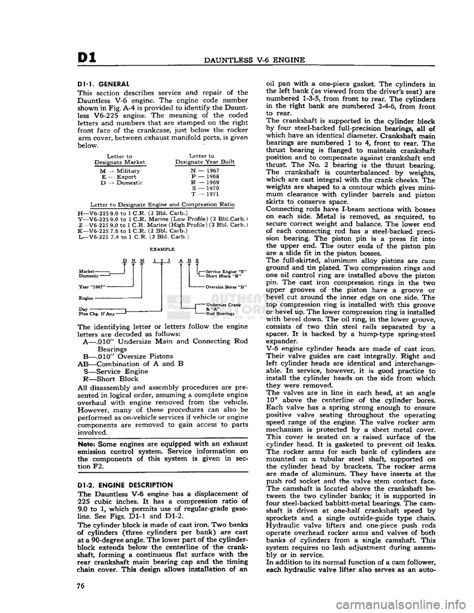
GENERAL
This
section describes service and repair of the
Dauntless V-6 engine. The
engine
code
number shown in
Fig.
A-4 is provided to identify the Daunt
less
V6-225 engine. The meaning of the coded letters and numbers that are stamped on the right front face of the crankcase, just below the rocker
arm
cover,
between
exhaust manifold ports, is given
below.
Letter
to
Designate
Market
M
—
Military
E
—
Export
D
— Domestic
Letter
to
Designate
Year
Built
N
— 1967
P
— 1968
R
— 1969
S
— 1970
T
— 1971
Letter
to Designate
Engine
and Compression
Ratio
H—V6-225
9.0 to 1
C.R.
(2 Bbl.
Carb.)
Y—V6-225
9.0 to 1
C.R.
Marine
(Low
Profile)
(2
Bbl.Carb.)
Z—V6-225
9.0 to 1
C.R.
Marine
(High
Profile)
(2 Bbl.
Carb.)
K—V6-225
7.6 to 1
C.R.
(2 Bbl.
Carb.)
L—V6-225
7.4 to 1
C.R.
(2 Bbl.
Carb.)
Market
Domestic
—
Year
"1967"
Engine
J
Day
Plus Chg. If
Any-
Service Engine "S"
Short
Block
"R" -Oversize Bores "B"
Undersize Crank
&
"A"
Rod
Bearings
The
identifying letter or letters follow the
engine
letters are decoded as follows:
A—.010"
Undersize
Main
and Connecting Rod
Bearings
B—.010"
Oversize Pistons
AB—Combination
of A and B
S—Service
Engine
R—Short
Block
All
disassembly and assembly procedures are pre sented in logical order, assuming a complete
engine
overhaul
with
engine
removed from the vehicle.
However,
many of
these
procedures can also be
performed as on-vehicle services if vehicle or
engine
components are removed to gain access to parts
involved.
Note:
Some
engines
are equipped with an exhaust
emission control system. Service information on
the components of this system is given in sec tion F2.
Dl-2.
ENGINE
DESCRIPTION
The
Dauntless V-6
engine
has a displacement of
225 cubic inches. It has a compression ratio of
9.0 to 1, which permits use of regular-grade
gaso
line.
See
Figs.
Dl-1 and Dl-2.
The
cylinder block is made of cast
iron.
Two banks
of cylinders (three cylinders per bank) are cast at a
90-degree
angle. The lower part of the cylinder-
block
extends
below the centerline of the
crank
shaft, forming a continuous flat surface with the
rear
crankshaft main bearing cap and the timing
chain
cover.
This
design allows installation of an
oil
pan with a
one-piece
gasket. The cylinders in
the left bank (as viewed from the driver's seat) are
numbered
1-3-5,
from front to
rear.
The cylinders
in
the right bank are numbered
2-4-6,
from front
to
rear.
The
crankshaft is supported in the cylinder block
by four steel-backed full-precision bearings, all of
which
have an identical diameter.
Crankshaft
main bearings are numbered 1 to 4, front to
rear.
The
thrust
bearing is flanged to maintain crankshaft position and to compensate against crankshaft end
thrust
The No. 2 bearing is the thrust bearing.
The
crankshaft is counterbalanced by weights,
which
are cast integral with the
crank
cheeks. The
weights
are shaped to a contour which
gives
mini
mum
clearance with cylinder barrels and piston
skirts
to conserve space.
Connecting
rods have I-beam sections with
bosses
on each side. Metal is removed, as required, to secure correct weight and balance. The lower end
of each connecting rod has a steel-backed preci
sion bearing. The piston pin is a press fit into the upper end. The outer ends of the piston pin
are
a slide fit in the piston
bosses.
The
full-skirted, aluminum alloy pistons are cam ground and tin plated. Two compression rings and
one oil control ring are installed above the piston
pin.
The cast iron compression rings in the two
upper
grooves
of the piston have a
groove
or bevel cut around the inner
edge
on one side. The
top compression ring is installed with this
groove
or
bevel up. The lower compression ring is installed
with
bevel down. The oil
ring,
in the lower groove,
consists of two thin steel
rails
separated by a
spacer.
It is backed by a hump-type spring-steel
expander.
V-6
engine
cylinder heads are made of cast
iron.
Their
valve
guides
are cast integrally. Right and left cylinder heads are identical and interchange
able. In service, however, it is
good
practice to
install
the cylinder heads on the side from which
they were removed.
The
valves are in line in each head, at an angle
10°
above the centerline of the cylinder bores.
Each
valve has a spring strong enough to ensure
positive valve seating throughout the operating speed range of the engine. The valve rocker arm
mechanism is protected by a
sheet
metal cover.
This
cover is seated on a raised surface of the
cylinder
head. It is gasketed to prevent oil leaks.
The
rocker arms for each bank of cylinders are mounted on a tubular steel shaft, supported on
the cylinder head by brackets. The rocker arms
are
made of aluminum. They have inserts at the
push
rod socket and the valve stem contact face.
The
camshaft is located above the crankshaft be
tween the two cylinder banks; it is supported in
four steel-backed babbitt-metal bearings. The cam shaft is driven at one-half crankshaft speed by
sprockets and a single outside-guide type chain.
Hydraulic
valve lifters and
one-piece
push rods operate overhead rocker arms and valves of both
banks
of cylinders from a single camshaft.
This
system requires no lash adjustment during assem
bly
or in service.
In
addition to its normal function of a cam follower,
each hydraulic valve lifter also serves as an auto- 76