warning JEEP COMMANDER 2010 1.G Workshop Manual
[x] Cancel search | Manufacturer: JEEP, Model Year: 2010, Model line: COMMANDER, Model: JEEP COMMANDER 2010 1.GPages: 460, PDF Size: 7.11 MB
Page 94 of 460
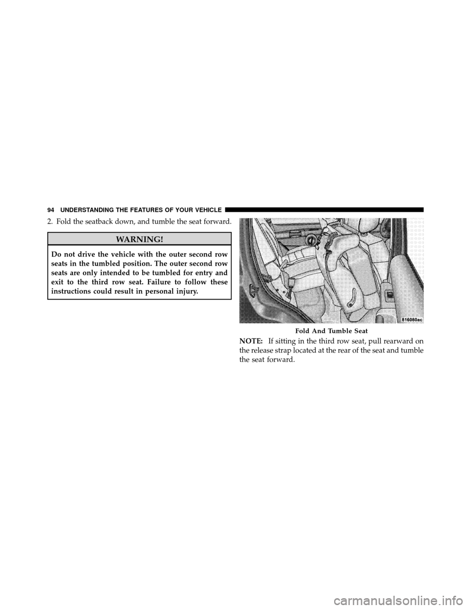
2. Fold the seatback down, and tumble the seat forward.
WARNING!
Do not drive the vehicle with the outer second row
seats in the tumbled position. The outer second row
seats are only intended to be tumbled for entry and
exit to the third row seat. Failure to follow these
instructions could result in personal injury.NOTE:If sitting in the third row seat, pull rearward on
the release strap located at the rear of the seat and tumble
the seat forward.
Fold And Tumble Seat
94 UNDERSTANDING THE FEATURES OF YOUR VEHICLE
Page 98 of 460
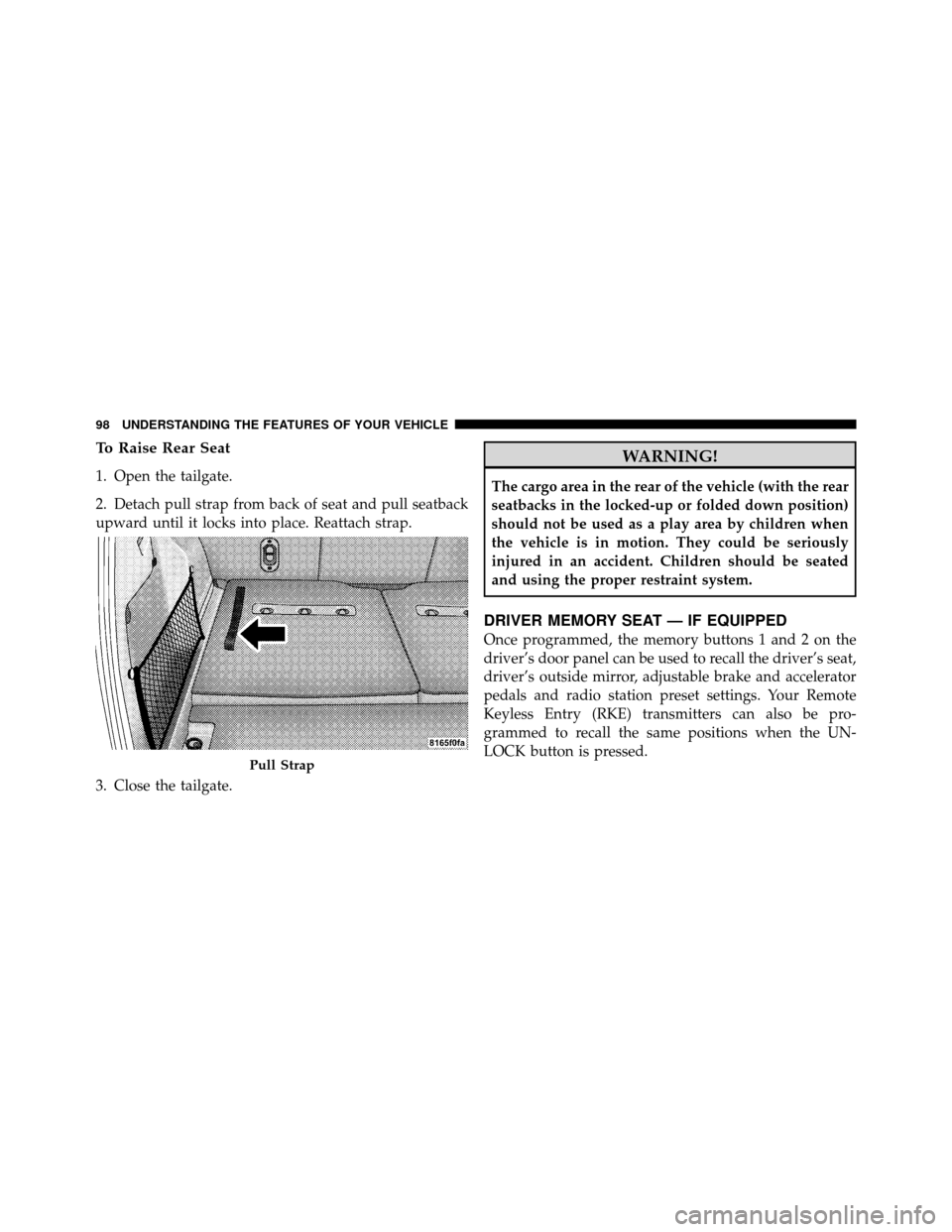
To Raise Rear Seat
1. Open the tailgate.
2. Detach pull strap from back of seat and pull seatback
upward until it locks into place. Reattach strap.
3. Close the tailgate.
WARNING!
The cargo area in the rear of the vehicle (with the rear
seatbacks in the locked-up or folded down position)
should not be used as a play area by children when
the vehicle is in motion. They could be seriously
injured in an accident. Children should be seated
and using the proper restraint system.
DRIVER MEMORY SEAT — IF EQUIPPED
Once programmed, the memory buttons 1 and 2 on the
driver’s door panel can be used to recall the driver’s seat,
driver’s outside mirror, adjustable brake and accelerator
pedals and radio station preset settings. Your Remote
Keyless Entry (RKE) transmitters can also be pro-
grammed to recall the same positions when the UN-
LOCK button is pressed.
Pull Strap
98 UNDERSTANDING THE FEATURES OF YOUR VEHICLE
Page 104 of 460
WARNING!
If the hood is not fully latched, it could fly up when
the vehicle is moving and block your forward vision.
Be sure all hood latches are fully latched before
driving.
LIGHTS
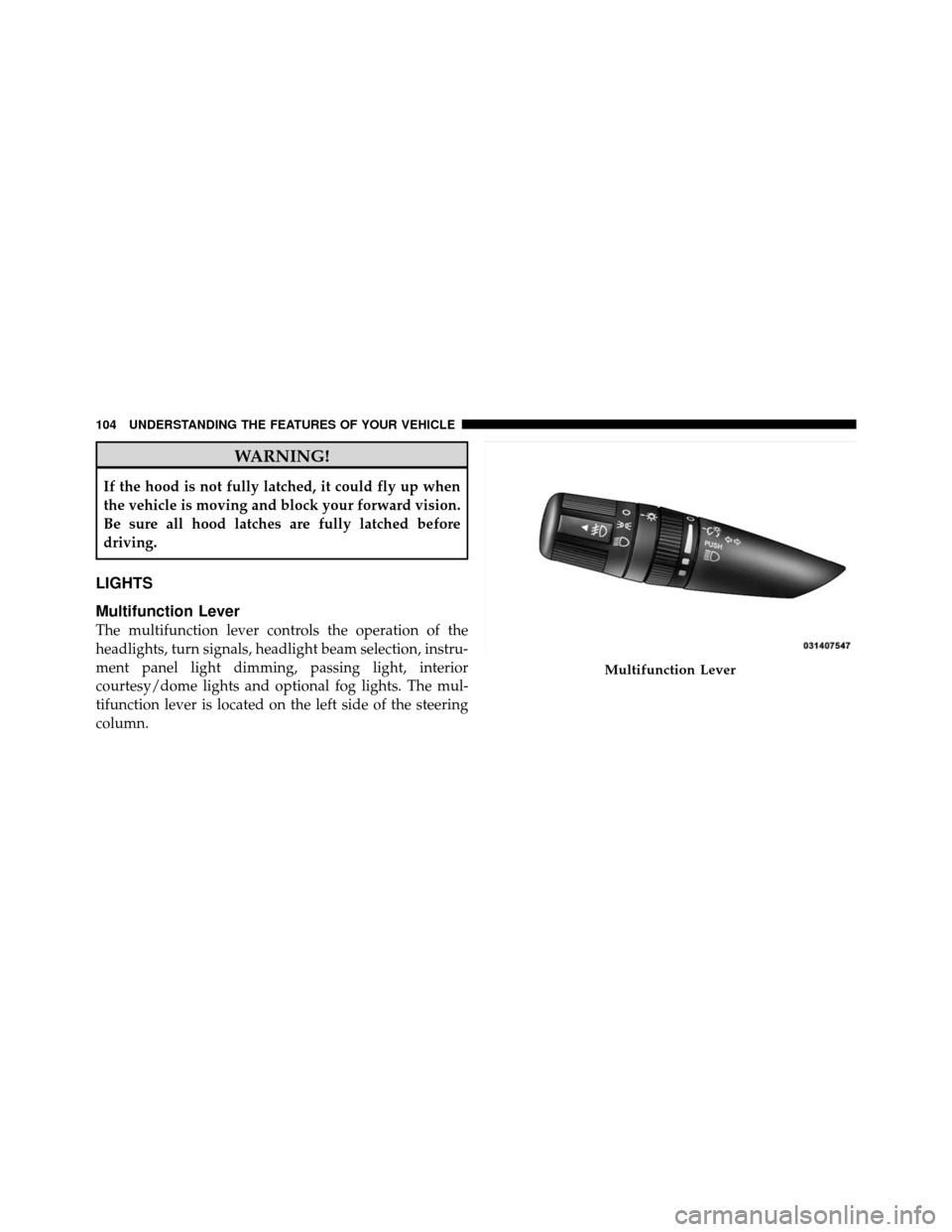
Multifunction Lever
The multifunction lever controls the operation of the
headlights, turn signals, headlight beam selection, instru-
ment panel light dimming, passing light, interior
courtesy/dome lights and optional fog lights. The mul-
tifunction lever is located on the left side of the steering
column.
Multifunction Lever
104 UNDERSTANDING THE FEATURES OF YOUR VEHICLE
Page 114 of 460
WARNING!
Sudden loss of visibility through the windshield
could lead to an accident. You might not see other
vehicles or other obstacles. To avoid sudden icing of
the windshield during freezing weather, warm the
windshield with the defroster before and during
windshield washer use.
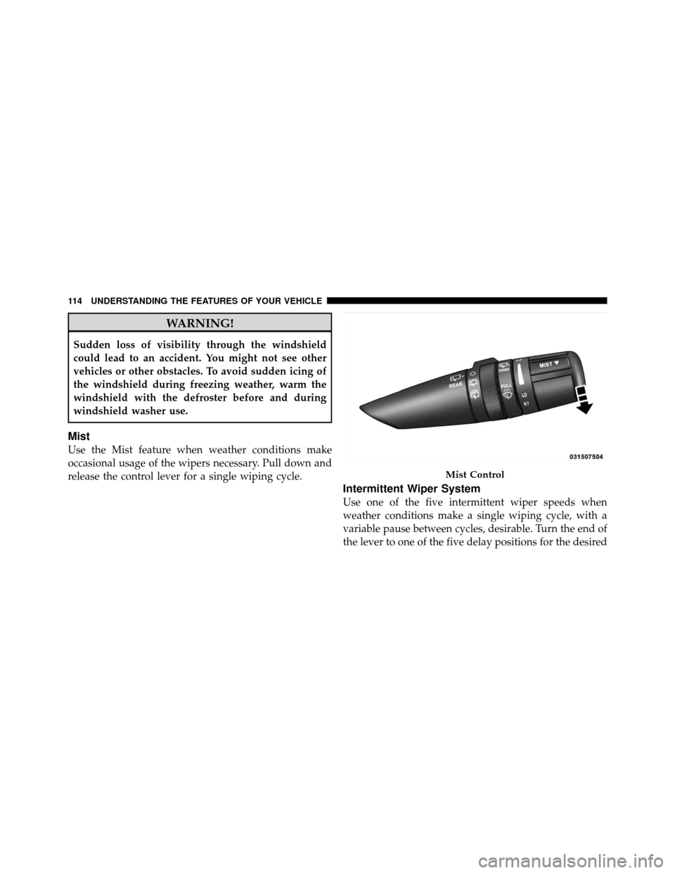
Mist
Use the Mist feature when weather conditions make
occasional usage of the wipers necessary. Pull down and
release the control lever for a single wiping cycle.
Intermittent Wiper System
Use one of the five intermittent wiper speeds when
weather conditions make a single wiping cycle, with a
variable pause between cycles, desirable. Turn the end of
the lever to one of the five delay positions for the desired
Mist Control
114 UNDERSTANDING THE FEATURES OF YOUR VEHICLE
Page 117 of 460
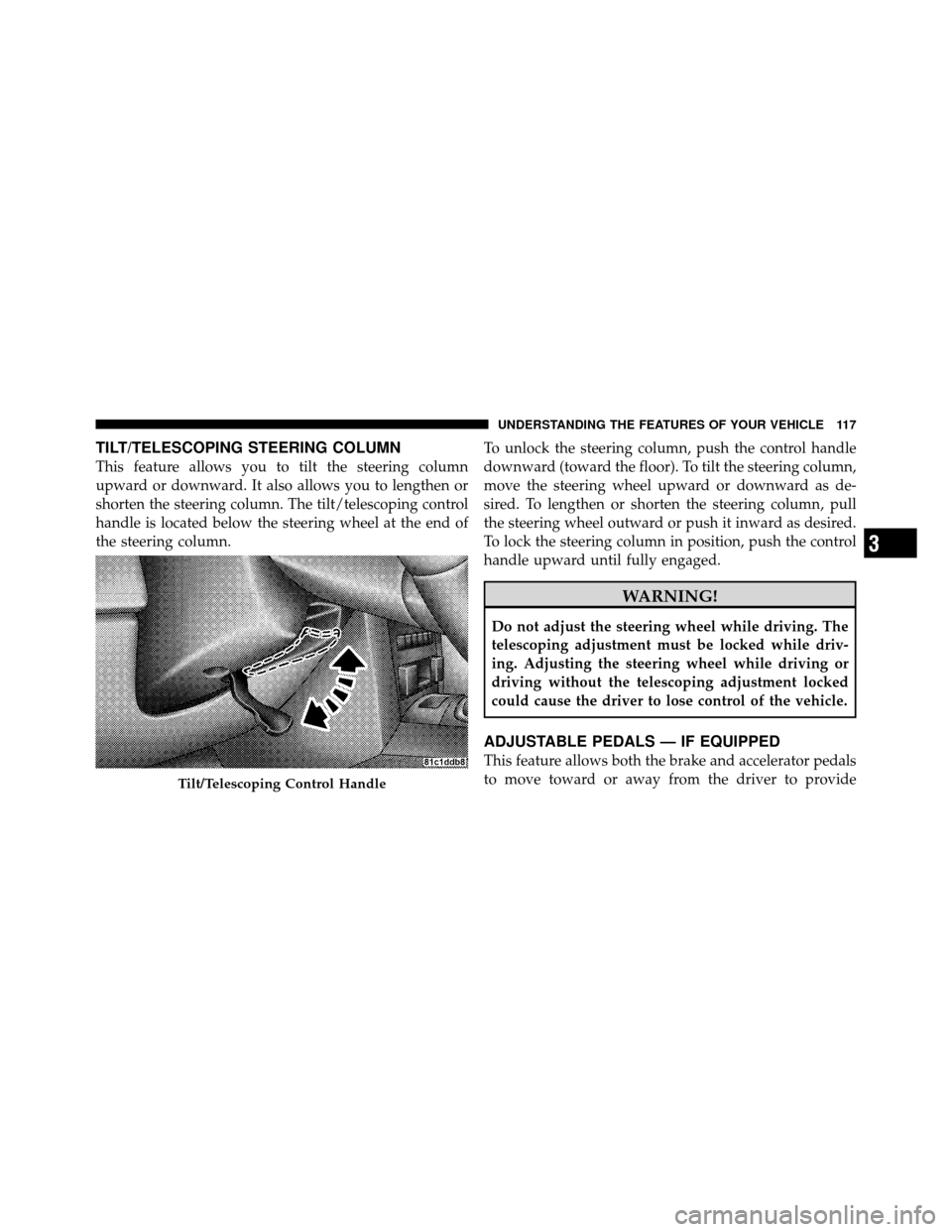
TILT/TELESCOPING STEERING COLUMN
This feature allows you to tilt the steering column
upward or downward. It also allows you to lengthen or
shorten the steering column. The tilt/telescoping control
handle is located below the steering wheel at the end of
the steering column.To unlock the steering column, push the control handle
downward (toward the floor). To tilt the steering column,
move the steering wheel upward or downward as de-
sired. To lengthen or shorten the steering column, pull
the steering wheel outward or push it inward as desired.
To lock the steering column in position, push the control
handle upward until fully engaged.
WARNING!
Do not adjust the steering wheel while driving. The
telescoping adjustment must be locked while driv-
ing. Adjusting the steering wheel while driving or
driving without the telescoping adjustment locked
could cause the driver to lose control of the vehicle.
ADJUSTABLE PEDALS — IF EQUIPPED
This feature allows both the brake and accelerator pedals
to move toward or away from the driver to provide
Tilt/Telescoping Control Handle
3
UNDERSTANDING THE FEATURES OF YOUR VEHICLE 117
Page 119 of 460
CAUTION!
Do not place any article under the adjustable pedal’s
or impede its ability to move as it may cause damage
to the pedal controls. Pedal travel may become lim-
ited if movement is stopped by an obstruction in the
adjustable pedal’s path.
WARNING!
Do not adjust the pedals while the vehicle is moving.
You could lose control and have an accident. Always
adjust the pedals while the vehicle is parked.
ELECTRONIC SPEED CONTROL — IF EQUIPPED
When engaged, Electronic Speed Control takes over
accelerator operations at speeds greater than 25 mph
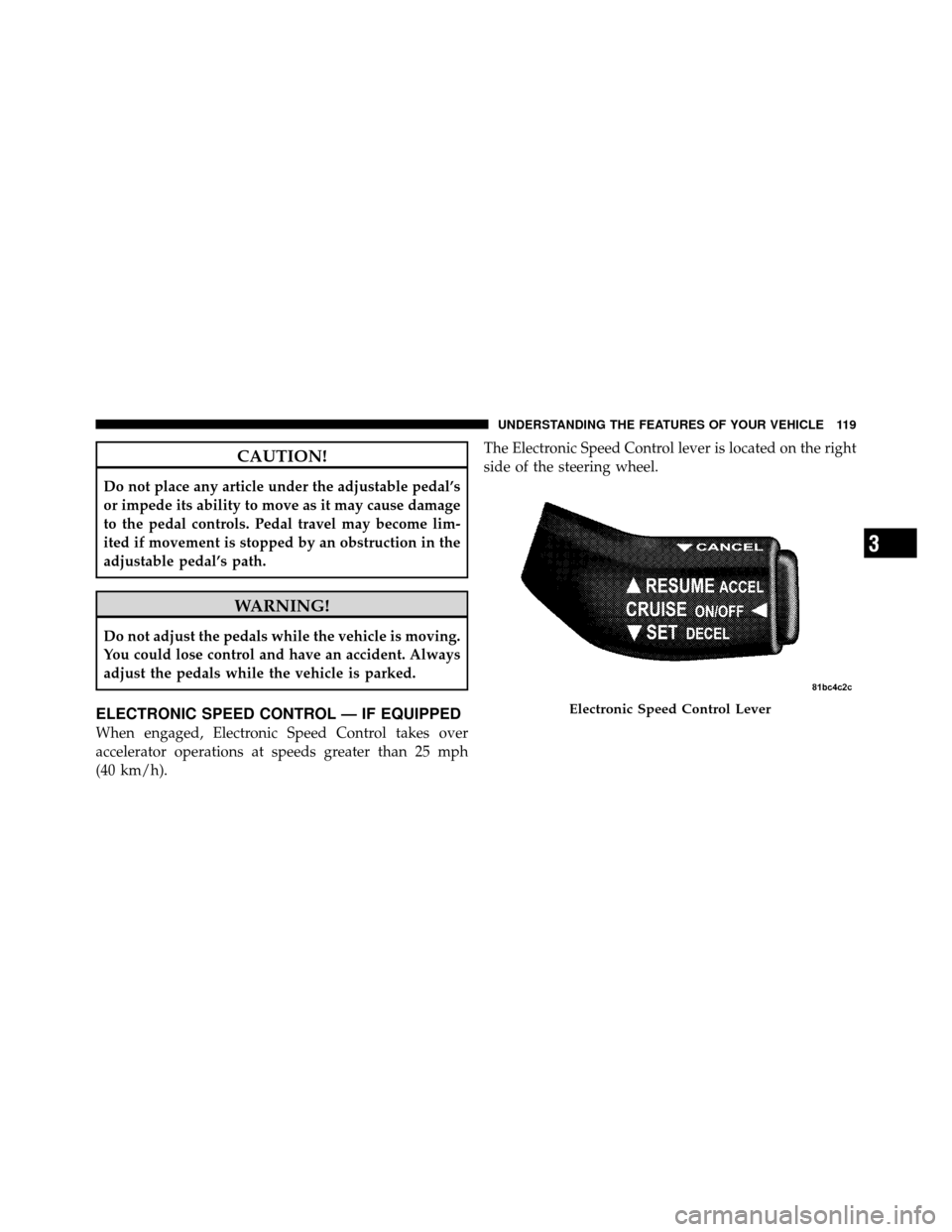
(40 km/h).The Electronic Speed Control lever is located on the right
side of the steering wheel.
Electronic Speed Control Lever
3
UNDERSTANDING THE FEATURES OF YOUR VEHICLE 119
Page 120 of 460
NOTE:In order to ensure proper operation, the Elec-
tronic Speed Control System has been designed to shut
down if multiple Speed Control functions are operated
simultaneously. If this occurs, the Electronic Speed Con-
trol System can be reactivated by pushing the Electronic
Speed Control ON/OFF button and resetting the desired
vehicle set speed.
To Activate
Push the ON/OFF button. The Cruise Indicator Light in
the instrument cluster will illuminate. To turn the Elec-
tronic Speed Control system OFF, push the ON/OFF
button a second time. The Cruise Indicator Light will
turn off. The Electronic Speed Control system should be
turned OFF when not in use.
WARNING!
Leaving the Electronic Speed Control system on
when not in use is dangerous. You could accidentally
set the Electronic Speed Control or cause it to go
faster than you want. You could lose control and have
an accident. Always leave the Electronic Speed Con-
trol system OFF when you are not using it.
To Set a Desired Speed
When the vehicle has reached the desired speed, press
down on the Electronic Speed Control lever and release.
Release the accelerator and the vehicle will operate at the
selected speed.
NOTE: The vehicle should be traveling at a steady
speed and on level ground before pressing the SET lever.
120 UNDERSTANDING THE FEATURES OF YOUR VEHICLE
Page 122 of 460
NOTE:
•The Electronic Speed Control System maintains speed
up and down hills. A slight speed change on moderate
hills is normal.
•On steep hills a greater speed loss or gain may occur so
it may be preferable to drive without Electronic Speed
Control.
REAR PARK ASSIST — IF EQUIPPED
The Rear Park Assist provides visible and audible indi-
cations of the distance between the rear fascia and the
detected obstacle when backing up. Refer to the Warning
Section and Note Section for limitations of this system
and recommendations.
The Rear Park Assist will remember the last system state
(enabled or disabled) from the last ignition cycle when
the ignition is changed to the ON position.The Rear Park Assist can be active only when the shift
lever is in REVERSE. If the Rear Park Assist is enabled at
this shift lever position, the system will be active until the
vehicle speed is increased to approximately 11 mph
(18 km/h) or above. The system will be active again if the
vehicle speed is decreased to speeds less than approxi-
mately 10 mph (16 km/h).
Rear Park Assist Sensors
The four Rear Park Assist Sensors, located in the rear
fascia, monitor the area behind the vehicle that is within
the sensors’ field of view.
The sensors can detect obstacles from approximately 12
to 59 in (30 to 150 cm) from the rear fascia in the
horizontal direction, depending on the location and
orientation of the obstacle and the type of obstacle.
122 UNDERSTANDING THE FEATURES OF YOUR VEHICLE
Page 123 of 460
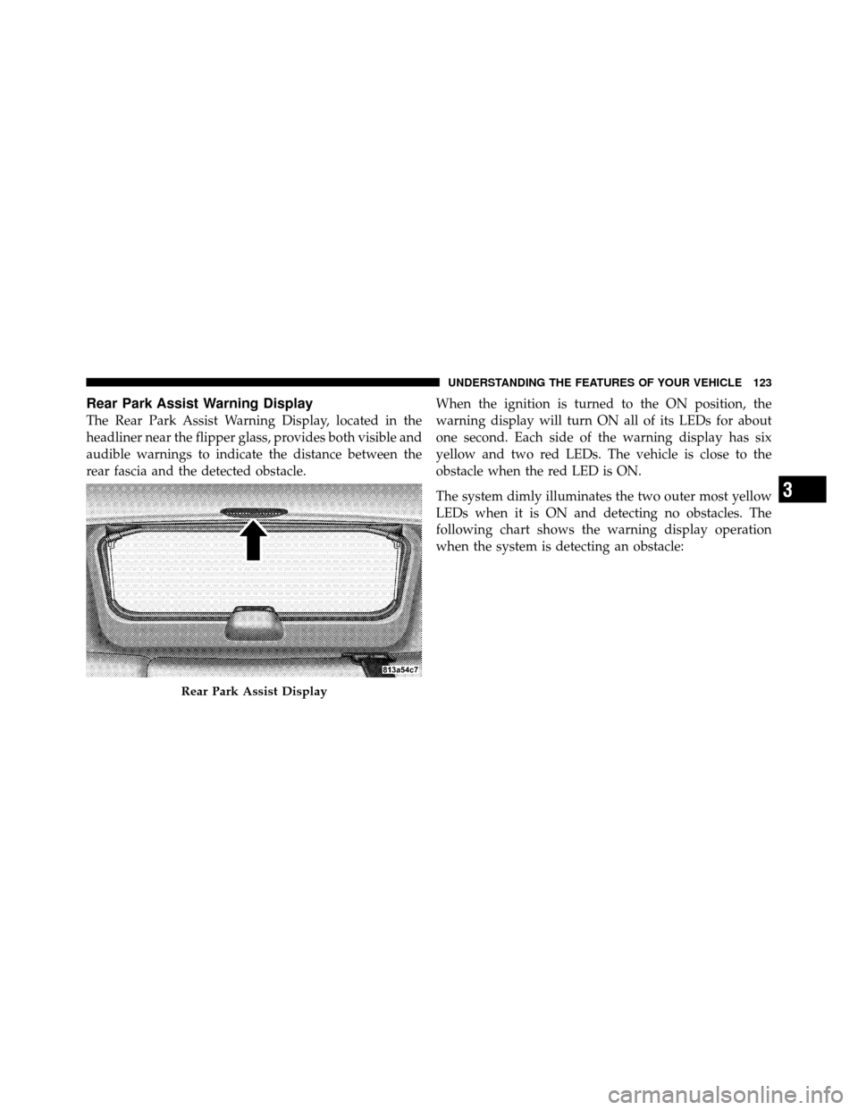
Rear Park Assist Warning Display
The Rear Park Assist Warning Display, located in the
headliner near the flipper glass, provides both visible and
audible warnings to indicate the distance between the
rear fascia and the detected obstacle.When the ignition is turned to the ON position, the
warning display will turn ON all of its LEDs for about
one second. Each side of the warning display has six
yellow and two red LEDs. The vehicle is close to the
obstacle when the red LED is ON.
The system dimly illuminates the two outer most yellow
LEDs when it is ON and detecting no obstacles. The
following chart shows the warning display operation
when the system is detecting an obstacle:
Rear Park Assist Display
3
UNDERSTANDING THE FEATURES OF YOUR VEHICLE 123
Page 124 of 460
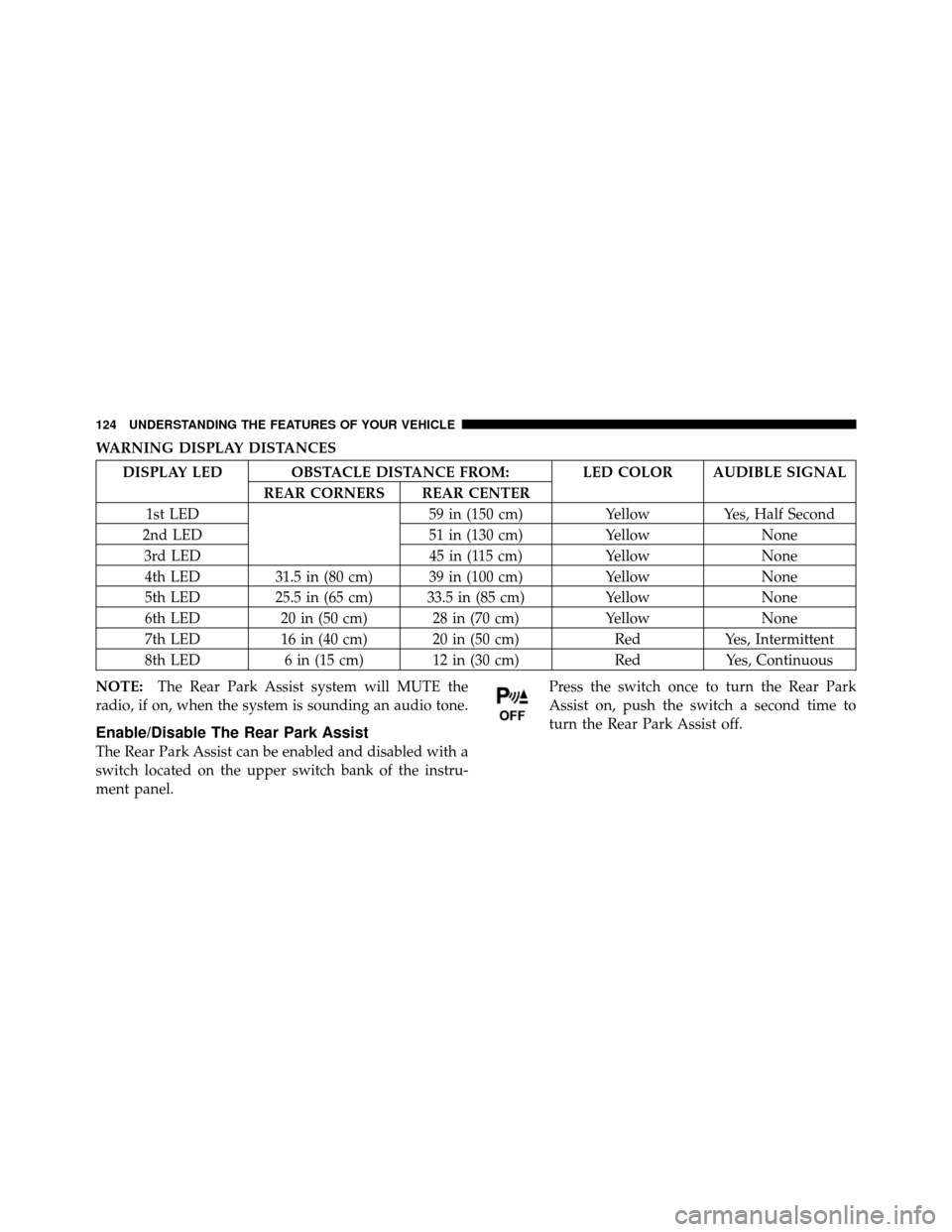
WARNING DISPLAY DISTANCES
DISPLAY LED OBSTACLE DISTANCE FROM: LED COLOR AUDIBLE SIGNALREAR CORNERS REAR CENTER
1st LED 59 in (150 cm)YellowYes, Half Second
2nd LED 51 in (130 cm)YellowNone
3rd LED 45 in (115 cm)YellowNone
4th LED 31.5 in (80 cm) 39 in (100 cm) YellowNone
5th LED 25.5 in (65 cm) 33.5 in (85 cm) YellowNone
6th LED 20 in (50 cm) 28 in (70 cm) YellowNone
7th LED 16 in (40 cm) 20 in (50 cm) RedYes, Intermittent
8th LED 6 in (15 cm) 12 in (30 cm) RedYes, Continuous
NOTE: The Rear Park Assist system will MUTE the
radio, if on, when the system is sounding an audio tone.
Enable/Disable The Rear Park Assist
The Rear Park Assist can be enabled and disabled with a
switch located on the upper switch bank of the instru-
ment panel. Press the switch once to turn the Rear Park
Assist on, push the switch a second time to
turn the Rear Park Assist off.
124 UNDERSTANDING THE FEATURES OF YOUR VEHICLE