instrument panel JEEP COMMANDER 2010 1.G User Guide
[x] Cancel search | Manufacturer: JEEP, Model Year: 2010, Model line: COMMANDER, Model: JEEP COMMANDER 2010 1.GPages: 78, PDF Size: 7.31 MB
Page 13 of 78
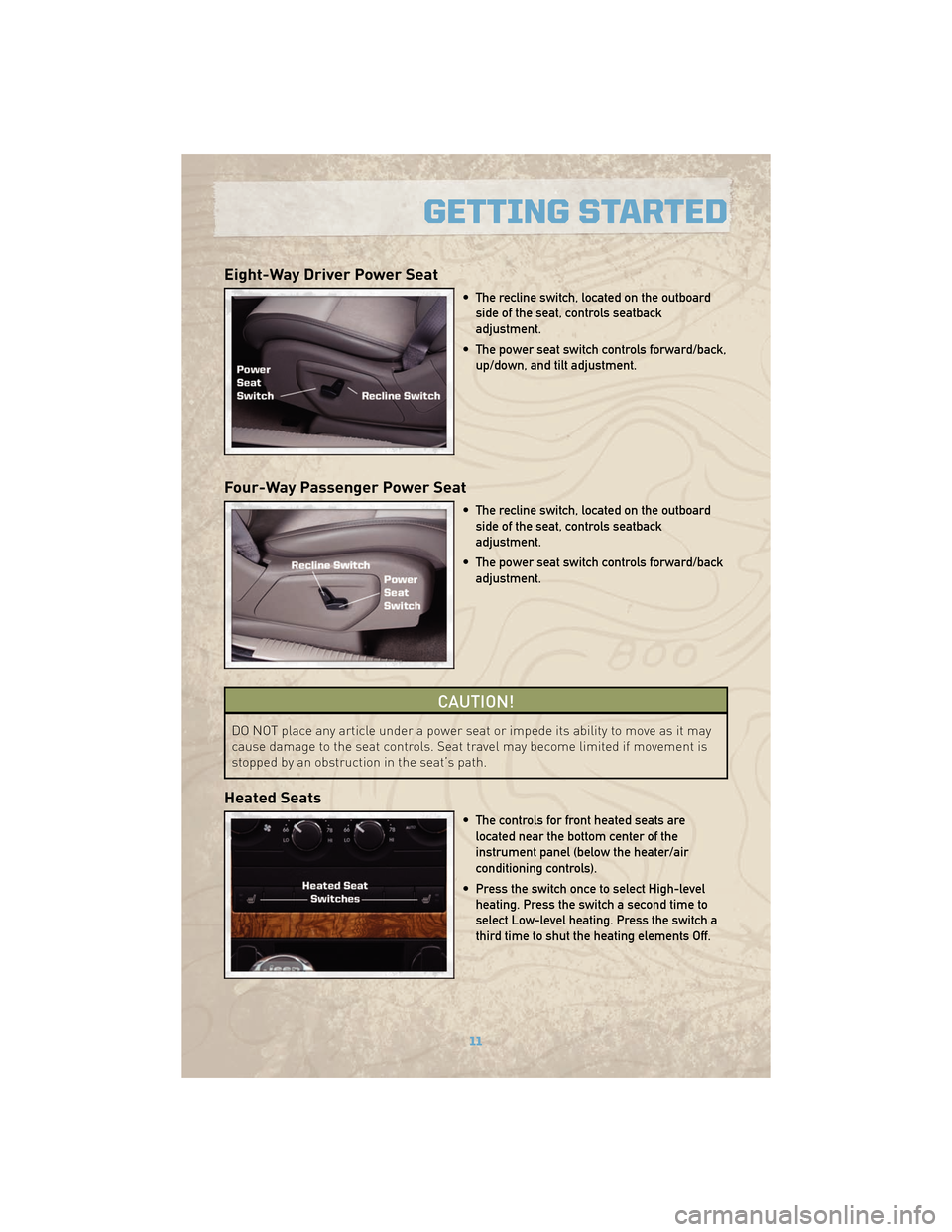
Eight-Way Driver Power Seat
• The recline switch, located on the outboardside of the seat, controls seatback
adjustment.
• The power seat switch controls forward/back, up/down, and tilt adjustment.
Four-Way Passenger Power Seat
• The recline switch, located on the outboardside of the seat, controls seatback
adjustment.
• The power seat switch controls forward/back adjustment.
CAUTION!
DO NOT place any article under a power seat or impede its ability to move as it may
cause damage to the seat controls. Seat travel may become limited if movement is
stopped by an obstruction in the seat’s path.
Heated Seats
• The controls for front heated seats arelocated near the bottom center of the
instrument panel (below the heater/air
conditioning controls).
• Press the switch once to select High-level heating. Press the switch a second time to
select Low-level heating. Press the switch a
third time to shut the heating elements Off.
11
GETTING STARTED
Page 18 of 78
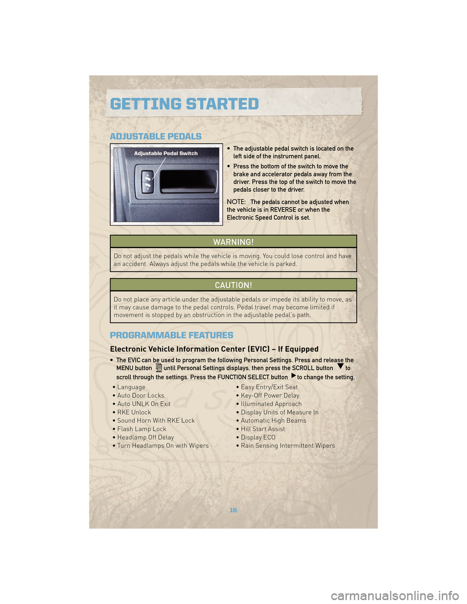
ADJUSTABLE PEDALS
• The adjustable pedal switch is located on theleft side of the instrument panel.
• Press the bottom of the switch to move the brake and accelerator pedals away from the
driver. Press the top of the switch to move the
pedals closer to the driver.
NOTE: The pedals cannot be adjusted when
the vehicle is in REVERSE or when the
Electronic Speed Control is set.
WARNING!
Do not adjust the pedals while the vehicle is moving. You could lose control and have
an accident. Always adjust the pedals while the vehicle is parked.
CAUTION!
Do not place any article under the adjustable pedals or impede its ability to move, as
it may cause damage to the pedal controls. Pedal travel may become limited if
movement is stopped by an obstruction in the adjustable pedal’s path.
PROGRAMMABLE FEATURES
Electronic Vehicle Information Center (EVIC) – If Equipped
• The EVIC can be used to program the following Personal Settings. Press and release the MENU button
until Personal Settings displays, then press the SCROLL buttonto
scroll through the settings. Press the FUNCTION SELECT button
to change the setting.
• Language • Easy Entry/Exit Seat
• Auto Door Locks • Key-Off Power Delay
• Auto UNLK On Exit • Illuminated Approach
• RKE Unlock • Display Units of Measure In
• Sound Horn With RKE Lock • Automatic High Beams
• Flash Lamp Lock • Hill Start Assist
• Headlamp Off Delay • Display ECO
• Turn Headlamps On with Wipers • Rain Sensing Intermittent Wipers
GETTING STARTED
16
Page 19 of 78
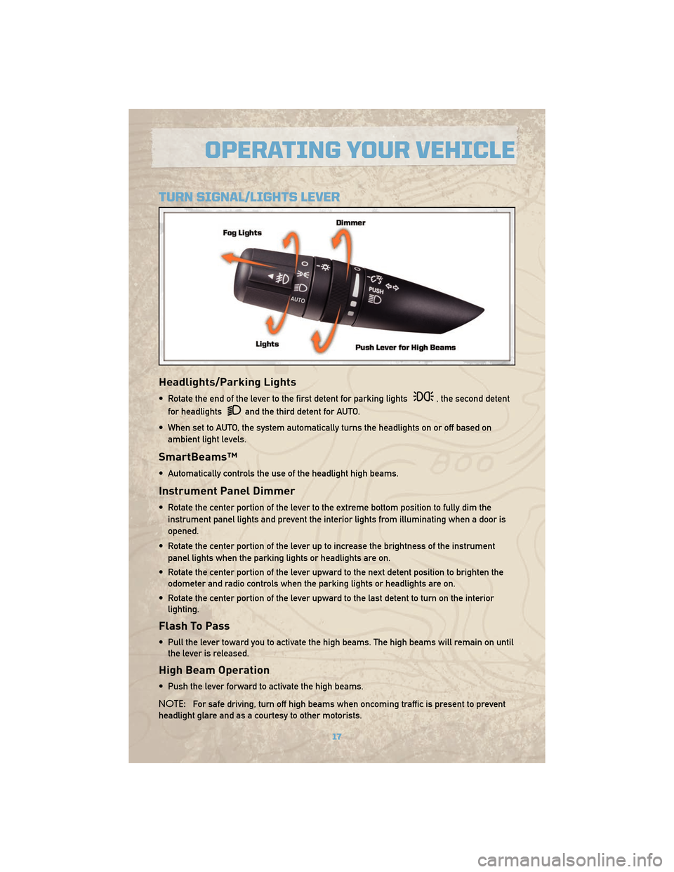
TURN SIGNAL/LIGHTS LEVER
Headlights/Parking Lights
• Rotate the end of the lever to the first detent for parking lights, the second detent
for headlights
and the third detent for AUTO.
• When set to AUTO, the system automatically turns the headlights on or off based on ambient light levels.
SmartBeams™
• Automatically controls the use of the headlight high beams.
Instrument Panel Dimmer
• Rotate the center portion of the lever to the extreme bottom position to fully dim theinstrument panel lights and prevent the interior lights from illuminating when a door is
opened.
• Rotate the center portion of the lever up to increase the brightness of the instrument panel lights when the parking lights or headlights are on.
• Rotate the center portion of the lever upward to the next detent position to brighten the odometer and radio controls when the parking lights or headlights are on.
• Rotate the center portion of the lever upward to the last detent to turn on the interior lighting.
Flash To Pass
• Pull the lever toward you to activate the high beams. The high beams will remain on untilthe lever is released.
High Beam Operation
• Push the lever forward to activate the high beams.
NOTE: For safe driving, turn off high beams when oncoming traffic is present to prevent
headlight glare and as a courtesy to other motorists.
17
OPERATING YOUR VEHICLE
Page 24 of 78
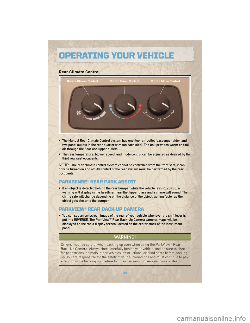
Rear Climate Control
• The Manual Rear Climate Control system has one floor air outlet (passenger side), andtwo panel outlets in the rear quarter trim (on each side). The unit provides warm or cool
air through the floor and upper outlets.
• The rear temperature, blower speed, and mode control can be adjusted as desired by the third row seat occupants.
NOTE: The rear climate control system cannot be controlled from the front seat; it can
only be turned on and off. All control of the rear system must be performed by the rear
occupants.
PARKSENSE® REAR PARK ASSIST
• If an object is detected behind the rear bumper while the vehicle is in REVERSE, a warning will display in the headliner near the flipper glass and a chime will sound. The
chime rate will change depending on the distance of the object, getting faster as the
object gets closer to the bumper.
PARKVIEW® REAR BACK-UP CAMERA
• You can see an on-screen image of the rear of your vehicle whenever the shift lever isput into REVERSE. The ParkView®Rear Back-Up Camera camera image will be
displayed on the radio display screen, located on the center stack of the instrument
panel.
WARNING!
Drivers must be careful when backing up even when using the ParkView®Rear
Back-Up Camera. Always check carefully behind your vehicle, and be sure to check
for pedestrians, animals, other vehicles, obstructions, or blind spots before backing
up. You are responsible for the safety of your surroundings and must continue to pay
attention while backing up. Failure to do so can result in serious injury or death.
OPERATING YOUR VEHICLE
22
Page 36 of 78
Programming A Rolling Code System
• At the garage door opener motor (in the garage), locate the “learn” or “training” button.This can usually be found where the hanging antenna wire is attached to the garage door
opener motor (it is NOT the button normally used to open and close the door).
• Firmly press and release the “learn” or “training” button. The name and color of the button may vary by manufacturer. Within 30 seconds, return to the vehicle and press the
programmed HomeLink
®button twice (holding the button for two seconds each time). If
the device is plugged in and activates, programming is complete.
• If the device does not activate, press the button a third time (for two seconds) to complete the training.
Using HomeLink®
• To operate, simply press and release the programmed HomeLink®button and the
trained device will operate.
• Refer to your Owner’s Manual on the DVD for further details. If you have any problems programming HomeLink
®, or require assistance, please call toll-free 1–800–355–3515,
or on the Internet, at www.HomeLink.com.
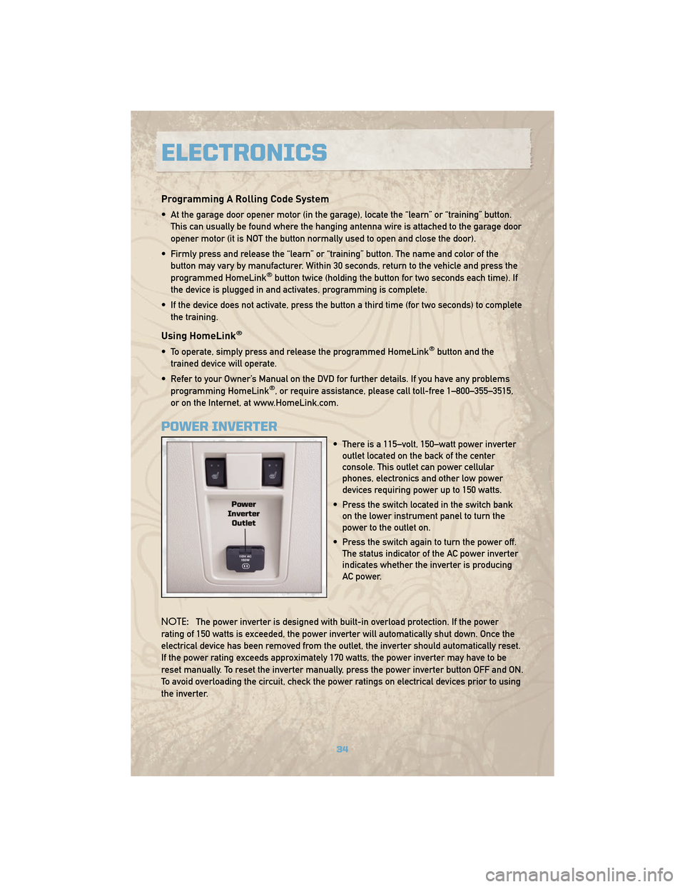
POWER INVERTER
• There is a 115–volt, 150–watt power inverter outlet located on the back of the center
console. This outlet can power cellular
phones, electronics and other low power
devices requiring power up to 150 watts.
• Press the switch located in the switch bank on the lower instrument panel to turn the
power to the outlet on.
• Press the switch again to turn the power off. The status indicator of the AC power inverter
indicates whether the inverter is producing
AC power.
NOTE: The power inverter is designed with built-in overload protection. If the power
rating of 150 watts is exceeded, the power inverter will automatically shut down. Once the
electrical device has been removed from the outlet, the inverter should automatically reset.
If the power rating exceeds approximately 170 watts, the power inverter may have to be
reset manually. To reset the inverter manually, press the power inverter button OFF and ON.
To avoid overloading the circuit, check the power ratings on electrical devices prior to using
the inverter.
ELECTRONICS
34
Page 37 of 78
WARNING!
To Avoid Serious Injury or Death: Do not use a three-prong adaptor. Do not insert any
objects into the receptacles. Do not touch with wet hands. Close the lid when not in
use. If this outlet is mishandled, it may cause an electric shock and failure.
POWER OUTLET
• The two front power outlets are located on the instrument panel below the ClimateControls. The right side outlet is powered only when the key is in the ON position. The left
side outlet is powered directly from the battery and will receive power whether the
ignition is in the ON or LOCK position. All accessories connected to the left outlet should
be removed or turned off when the vehicle is not in use to protect the battery against
discharge.
• The rear power outlet is located in the left rear cargo area and will receive power whether the ignition is in the ON or LOCK position. All accessories connected to the rear
outlet should be removed or turned off when the vehicle is not in use to protect the
battery against discharge.
NOTE: Do not exceed the maximum power of 160 Watts (13 Amps) at 12 Volts. If the 160
Watt (13 Amp) power rating is exceeded the fuse protecting the system will need to be
replaced.
uconnect™ phone
• The uconnect™ phone is a voice-activated, hands-free, in-vehicle communications system.
• The uconnect™ phone allows you to dial a phone number with your cellular phone using simple voice commands.
• Please refer to uconnect™ phone in the uconnect™ User's Manual on the DVD for further details.
WARNING!
• Any voice commanded system should be used only in safe driving conditions following local laws and phone use. All attention should be kept on the roadway
ahead. Failure to do so may result in an accident causing serious injury or death.
• Your phone must be turned on and paired to the uconnect™ phone to allow use of this vehicle feature in emergency situations, when the cellular phone has network
coverage and stays paired to the uconnect™ phone.
NOTE: The uconnect™ phone requires a cellular phone equipped with the Bluetooth
®
Hands-Free Profile, Version 0.96 or higher. For uconnect™ customer support, call
1–877–855–8400.
35
ELECTRONICS
Page 58 of 78
OPENING THE HOOD
• Pull the hood release lever located below the steering wheel at the base of theinstrument panel.
• Reach into the opening beneath the center of the hood and move the safety latch lever while lifting the hood at the same time.
WARNING!
Be sure the hood is fully latched before driving your vehicle. If the hood is not fully
latched, it could open when the vehicle is in motion and block your vision. Failure to
follow this warning could result in serious injury or death.
MAINTAINING YOUR VEHICLE
56
Page 68 of 78
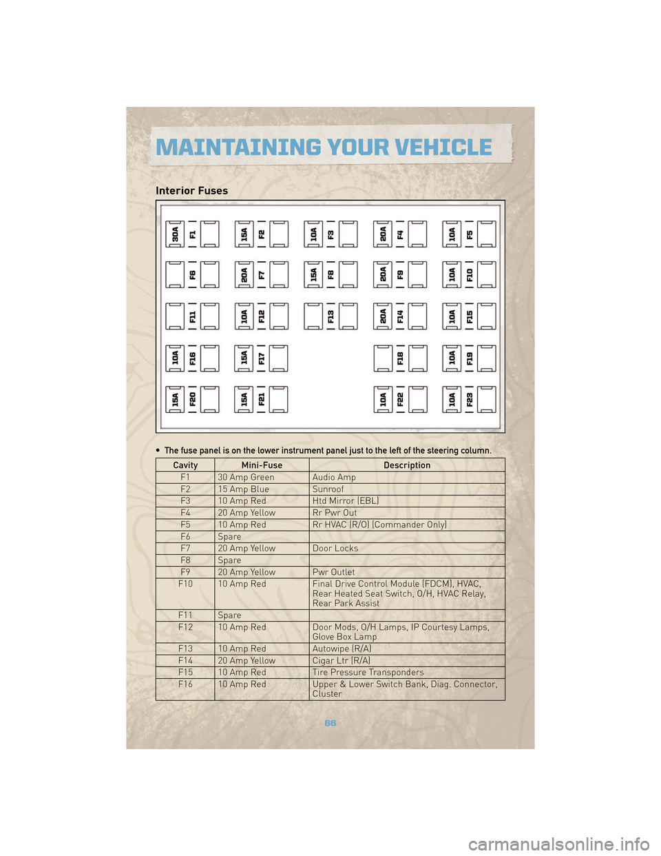
Interior Fuses
• The fuse panel is on the lower instrument panel just to the left of the steering column.
Cavity Mini-FuseDescription
F1 30 Amp Green Audio Amp
F2 15 Amp Blue Sunroof
F3 10 Amp Red Htd Mirror (EBL)
F4 20 Amp Yellow Rr Pwr Out
F5 10 Amp Red Rr HVAC (R/O) (Commander Only)
F6 Spare
F7 20 Amp Yellow Door Locks
F8 Spare
F9 20 Amp Yellow Pwr Outlet
F10 10 Amp Red Final Drive Control Module (FDCM), HVAC,
Rear Heated Seat Switch, O/H, HVAC Relay,
Rear Park Assist
F11 Spare
F12 10 Amp Red Door Mods, O/H Lamps, IP Courtesy Lamps,
Glove Box Lamp
F13 10 Amp Red Autowipe (R/A)
F14 20 Amp Yellow Cigar Ltr (R/A)
F15 10 Amp Red Tire Pressure Transponders
F16 10 Amp Red Upper & Lower Switch Bank, Diag. Connector,
Cluster
MAINTAINING YOUR VEHICLE
66