flat tire JEEP COMPASS 2013 1.G User Guide
[x] Cancel search | Manufacturer: JEEP, Model Year: 2013, Model line: COMPASS, Model: JEEP COMPASS 2013 1.GPages: 116, PDF Size: 2.71 MB
Page 71 of 116
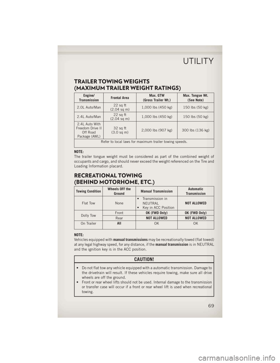
TRAILER TOWING WEIGHTS
(MAXIMUM TRAILER WEIGHT RATINGS)
Engine/
Transmission Frontal Area Max. GTW
(Gross Trailer Wt.) Max. Tongue Wt.
(See Note)
2.0L Auto/Man 22 sq ft
(2.04 sq m) 1,000 lbs (450 kg) 150 lbs (50 kg)
2.4L Auto/Man 22 sq ft
(2.04 sq m) 1,000 lbs (450 kg) 150 lbs (50 kg)
2.4L Auto With
Freedom Drive II Off Road
Package (AWL)32 sq ft
(3.0 sq m) 2,000 lbs (907 kg) 300 lbs (136 kg)
Refer to local laws for maximum trailer towing speeds.
NOTE:
The trailer tongue weight must be considered as part of the combined weight of
occupants and cargo, and should never exceed the weight referenced on the Tire and
Loading Information placard.
RECREATIONAL TOWING
(BEHIND MOTORHOME, ETC.)
Towing ConditionWheels OFF the Ground Manual Transmission Automatic
Transmission
Flat Tow None• Transmission in
NEUTRAL
• Key in ACC Position NOT ALLOWED
Dolly Tow Front
OK (FWD Only) OK (FWD Only)
Rear NOT ALLOWED NOT ALLOWED
On Trailer All
OK OK
NOTE:
Vehicles equipped withmanual transmissionsmay be recreationally towed (flat towed)
at any legal highway speed, for any distance, if themanual transmissionis in NEUTRAL
and the ignition key is in the ACC position.
CAUTION!
• Do not flat tow any vehicle equipped with a automatic transmission. Damage to the drivetrain will result. If these vehicles require towing, make sure all drive
wheels are off the ground.
•
Front or rear wheel lifts should not be used. Internal damage to the transmission
or transfer case will occur if a front or rear wheel lift is used when recreational
towing.
UTILITY
69
Page 72 of 116
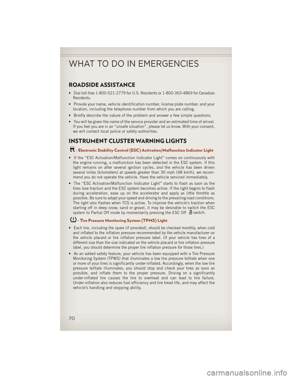
ROADSIDE ASSISTANCE
•Dial toll-free 1-800-521-2779 for U.S. Residents or 1-800-363-4869 for Canadian
Residents.
• Provide your name, vehicle identification number, license plate number, and your location, including the telephone number from which you are calling.
• Briefly describe the nature of the problem and answer a few simple questions.
• You will be given the name of the service provider and an estimated time of arrival. If you feel you are in an “unsafe situation”, please let us know. With your consent,
we will contact local police or safety authorities.
INSTRUMENT CLUSTER WARNING LIGHTS
- Electronic Stability Control (ESC) Activation/Malfunction Indicator Light
• If the “ESC Activation/Malfunction Indicator Light” comes on continuously withthe engine running, a malfunction has been detected in the ESC system. If this
light remains on after several ignition cycles, and the vehicle has been driven
several miles (kilometers) at speeds greater than 30 mph (48 km/h), we recom-
mend you do not operate the vehicle. Have the vehicle serviced immediately.
• The “ESC Activation/Malfunction Indicator Light” starts to flash as soon as the tires lose traction and the ESC system becomes active. If the light begins to flash
during acceleration, ease up on the accelerator and apply as little throttle as
possible. Be sure to adapt your speed and driving to the prevailing road conditions.
The light also flashes when TCS is active. To improve the vehicle's traction when
starting off in deep snow, sand or gravel, it may be desirable to switch the ESC
system to Partial Off mode by momentarily pressing the ESC Off
switch.
- Tire Pressure Monitoring System (TPMS) Light
•Each tire, including the spare (if provided), should be checked monthly, when cold
and inflated to the inflation pressure recommended by the vehicle manufacturer on
the vehicle placard or tire inflation pressure label. (If your vehicle has tires of a
different size than the size indicated on the vehicle placard or tire inflation pressure
label, you should determine the proper tire inflation pressure for those tires.)
• As an added safety feature, your vehicle has been equipped with a Tire Pressure Monitoring System (TPMS) that illuminates a low tire pressure telltale when one
or more of your tires is significantly under-inflated. Accordingly, when the low tire
pressure telltale illuminates, you should stop and check your tires as soon as
possible, and inflate them to the proper pressure. Driving on a significantly
under-inflated tire causes the tire to overheat and can lead to tire failure.
Under-inflation also reduces fuel efficiency and tire tread life, and may affect the
vehicle’s handling and stopping ability.
WHAT TO DO IN EMERGENCIES
70
Page 73 of 116
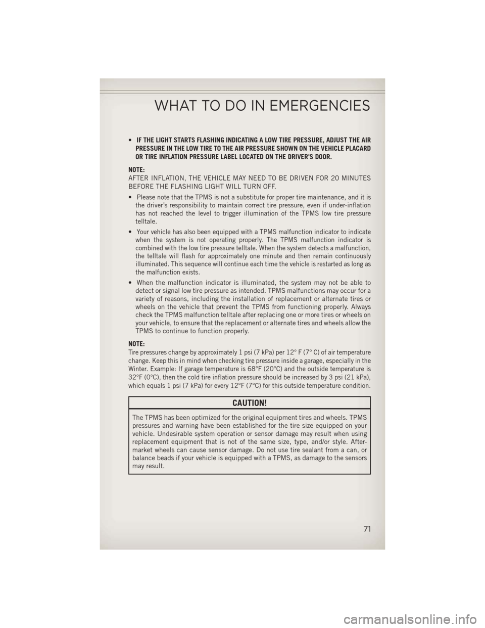
•IF THE LIGHT STARTS FLASHING INDICATING A LOW TIRE PRESSURE, ADJUST THE AIR
PRESSURE IN THE LOW TIRE TO THE AIR PRESSURE SHOWN ON THE VEHICLE PLACARD
OR TIRE INFLATION PRESSURE LABEL LOCATED ON THE DRIVER'S DOOR.
NOTE:
AFTER INFLATION, THE VEHICLE MAY NEED TO BE DRIVEN FOR 20 MINUTES
BEFORE THE FLASHING LIGHT WILL TURN OFF.
•
Please note that the TPMS is not a substitute for proper tire maintenance, and it is
the driver’s responsibility to maintain correct tire pressure, even if under-inflation
has not reached the level to trigger illumination of the TPMS low tire pressure
telltale.
•Your vehicle has also been equipped with a TPMS malfunction indicator to indicate
when the system is not operating properly. The TPMS malfunction indicator is
combined with the low tire pressure telltale. When the system detects a malfunction,
the telltale will flash for approximately one minute and then remain continuously
illuminated. This sequence will continue each time the vehicle is restarted as long as
the malfunction exists.
• When the malfunction indicator is illuminated, the system may not be able to detect or signal low tire pressure as intended. TPMS malfunctions may occur for a
variety of reasons, including the installation of replacement or alternate tires or
wheels on the vehicle that prevent the TPMS from functioning properly. Always
check the TPMS malfunction telltale after replacing one or more tires or wheels on
your vehicle, to ensure that the replacement or alternate tires and wheels allow the
TPMS to continue to function properly.
NOTE:
Tire pressures change by approximately 1 psi (7 kPa) per 12° F (7° C) of air temperature
change. Keep this in mind when checking tire pressure inside a garage, especially in the
Winter. Example: If garage temperature is 68°F (20°C) and the outside temperature is
32°F (0°C), then the cold tire inflation pressure should be increased by 3 psi (21 kPa),
which equals 1 psi (7 kPa) for every 12°F (7°C) for this outside temperature condition.
CAUTION!
The TPMS has been optimized for the original equipment tires and wheels. TPMS
pressures and warning have been established for the tire size equipped on your
vehicle. Undesirable system operation or sensor damage may result when using
replacement equipment that is not of the same size, type, and/or style. After-
market wheels can cause sensor damage. Do not use tire sealant from a can, or
balance beads if your vehicle is equipped with a TPMS, as damage to the sensors
may result.
WHAT TO DO IN EMERGENCIES
71
Page 80 of 116
7. Finish tightening the nuts. Push down on the wrench while at the end of thehandle for increased leverage. Tighten the lug nuts in a star pattern until each nut
has been tightened twice. The correct wheel nut torque is 100 ft lbs (135 N·m).
If you doubt that you have tightened the nuts correctly, have them checked with
a torque wrench by your authorized dealer or service station.
8. Remove the wheel blocks and lower the jack until it is free. Reassemble the lug wrench to the jack assembly and stow it in the spare tire area. Secure the
assembly using the means provided.
9. Place the deflated (flat) tire in the cargo area, have the tire repaired or replaced as
soon as possible.
10. Check the spare tire pressure as soon as possible. Correct the tire pressure as required.
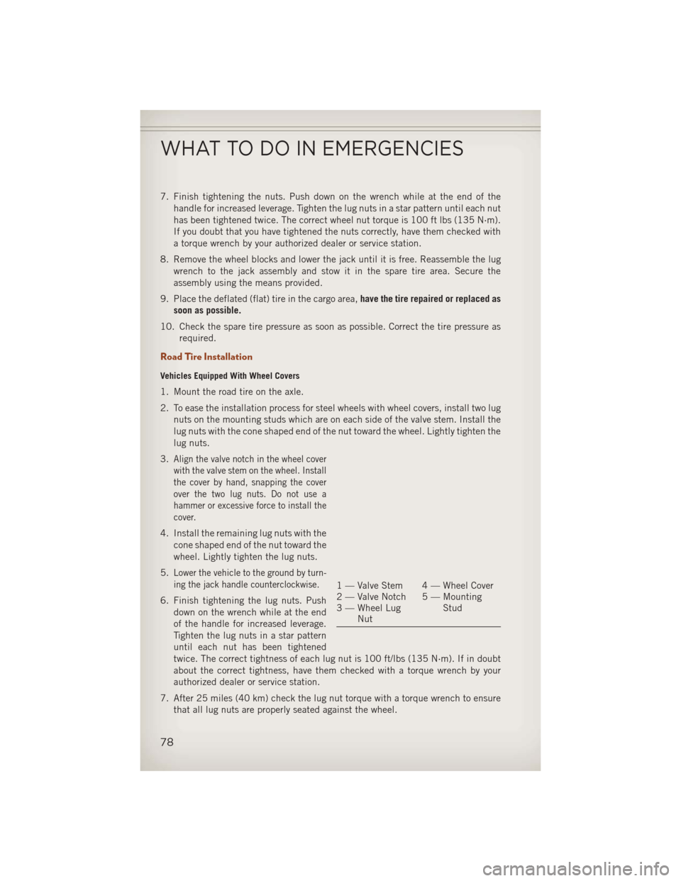
Road Tire Installation
Vehicles Equipped With Wheel Covers
1. Mount the road tire on the axle.
2. To ease the installation process for steel wheels with wheel covers, install two lugnuts on the mounting studs which are on each side of the valve stem. Install the
lug nuts with the cone shaped end of the nut toward the wheel. Lightly tighten the
lug nuts.
3.
Align the valve notch in the wheel cover
with the valve stem on the wheel. Install
the cover by hand, snapping the cover
over the two lug nuts. Do not use a
hammer or excessive force to install the
cover.
4. Install the remaining lug nuts with the cone shaped end of the nut toward the
wheel. Lightly tighten the lug nuts.
5.
Lower the vehicle to the ground by turn-
ing the jack handle counterclockwise.
6. Finish tightening the lug nuts. Push down on the wrench while at the end
of the handle for increased leverage.
Tighten the lug nuts in a star pattern
until each nut has been tightened
twice. The correct tightness of each lug nut is 100 ft/lbs (135 N·m). If in doubt
about the correct tightness, have them checked with a torque wrench by your
authorized dealer or service station.
7. After 25 miles (40 km) check the lug nut torque with a torque wrench to ensure that all lug nuts are properly seated against the wheel.
1 — Valve Stem 4 — Wheel Cover
2 — Valve Notch 5 — Mounting Stud
3 — Wheel Lug
Nut
WHAT TO DO IN EMERGENCIES
78
Page 82 of 116
WARNING!
• Being under a jacked-up vehicle is dangerous. The vehicle could slip off thejack and fall on you. You could be crushed. Never put any part of your body
under a vehicle that is on a jack. If you need to get under a raised vehicle, take
it to a service center where it can be raised on a lift.
• Never start or run the engine while the vehicle is on a jack.
• The jack is designed to be used as a tool for changing tires only. The jack
should not be used to lift the vehicle for service purposes. The vehicle should
be jacked on a firm level surface only. Avoid ice or slippery areas.
• Do not attempt to change a tire on the side of the vehicle close to moving
traffic, pull far enough off the road to avoid the danger of being hit when
operating the jack or changing the wheel.
• Carefully follow these tire changing warnings to help prevent personal injury or
damage to your vehicle:
• Always park on a firm, level surface as far from the edge of the roadwayas possible before raising the vehicle.
• Turn on the Hazard Warning flasher.
• Block the wheel diagonally opposite the wheel to be raised.
• Set the parking brake firmly and set an automatic transmission in PARK;
a manual transmission in REVERSE.
• Do not let anyone sit in the vehicle when it is on a jack.
• Do not get under the vehicle when it is on a jack.
• Only use the jack in the positions indicated and for lifting this vehicle during
a tire change.
• If working on or near a roadway, be extremely careful of motor traffic.
• To assure that spare tires, flat or inflated, are securely stowed, spares must be
stowed with the valve stem facing the ground.
• Raising the vehicle higher than necessary can make the vehicle less stable.
It could slip off the jack and hurt someone near it. Raise the vehicle only
enough to remove the tire.
• To avoid possible personal injury, handle the wheel covers with care to avoid
contact with any sharp edges.
• A loose tire or jack thrown forward in a collision or hard stop could injure the
occupants in the vehicle. Have the deflated (flat) tire repaired or replaced
immediately.
• To avoid the risk of forcing the vehicle off the jack, do not tighten the lug nuts
fully until the vehicle is lowered to the ground. Failure to follow this warning
may result in personal injury.
WHAT TO DO IN EMERGENCIES
80
Page 94 of 116
Your authorized dealer will reset the oil change indicator message after completing
the scheduled oil change. If a scheduled oil change is performed by someone other
than your authorized dealer, the message can be reset by referring to the steps
described under “Electronic Vehicle Information Center (EVIC)/Oil Change Re-
quired” in “Understanding Your Instrument Panel” or under “Instrument Cluster
Description/Odometer/Trip Odometer” in “Understanding Your Instrument Panel” for
further information.
NOTE:
Under no circumstances should oil change intervals exceed 10,000 miles (16,000 km)
or twelve months, whichever comes first.
Once A Month Or Before A Long Trip:
• Check engine oil level
• Check windshield washer fluid level
• Check the tire inflation pressures and look for unusual wear or damage
• Check the fluid levels of the coolant reservoir, brake master cylinder, powersteering and fill as needed
• Check function of all interior and exterior lights
Required Maintenance Intervals.
Refer to the maintenance schedules on the following page for the required mainte-
nance intervals.
At Every Oil Change Interval As Indicated By Oil Change Indicator System:
• Change oil and filter
• Rotate the tires. Rotate at the first sign of irregular wear, even if it occurs before the oil
indicator system turns on.
• Inspect battery and clean and tighten terminals as required
• Inspect brake pads, shoes, rotors, drums, hoses and park brake
• Inspect engine cooling system protection and hoses
• Inspect exhaust system
• Inspect engine air cleaner if using in dusty or off-road conditions
MAINTAINING YOUR VEHICLE
92
Page 99 of 116
Cavity Cartridge Fuse Mini-FuseDescription
21 10 Amp Red IOD Feed Intrus Mod/Siren
(If Equipped)
22 10 Amp Red IGN RUN Heat/AC/Compass Sensor
23 15 Amp Lt Blue ENG ASD Relay Feed 3
24 15 Amp Lt Blue Power Sunroof Feed
25 10 Amp Red Heated Mirror (If Equipped)
26 15 Amp Lt Blue ENG ASD Relay Feed 2
27 10 Amp Red IGN RUN Only ORC Feed
28 10 Amp Red IGN RUN ORC/OCM Feed
29 Hot Car (No Fuse Required)
30 20 Amp Yellow Heated Seat (If Equipped)
31 10 Amp Red Headlamp Washer Relay Control
(If Equipped)
32 30 Amp Pink ENG ASD Control Feed 1
33 10 Amp Red ABS MOD/J1962 Conn/PCM
34 30 Amp Pink ABS Valve Feed
35 40 Amp Green ABS Pump Feed
36 30 Amp Pink Headlamp/Washer Control/Smart Glass
(If Equipped)
37 25 Amp Natural Diesel Fuel Heater (If Equipped)
TIRE PRESSURES
•Check the inflation pressure of each tire, including the spare tire, at least monthly
and inflate to the recommended pressure for your vehicle.
•The tire pressures recommended for your vehicle are found on the “Tire and Loading
Information” label located on the driver’s side door opening.
NOTE:
Refer to the Owner's Manual on the DVD for
more information regarding tire warnings
and instructions.
MAINTAINING YOUR VEHICLE
97
Page 100 of 116
WARNING!
• Overloading of your tires is dangerous. Overloading can cause tire failure,affect vehicle handling, and increase your stopping distance. Use tires of the
recommended load capacity for your vehicle. Never overload them.
•
Improperly inflated tires are dangerous and can cause collisions. Under-inflation
is the leading cause of tire failure and may result in severe cracking, component
separation, or “blow out”. Over-inflation reduces a tire’s ability to cushion shock.
Objects on the road and chuck holes can cause damage that results in tire failure.
Unequal tire pressures can cause steering problems. You could lose control of
your vehicle. Over-inflated or under-inflated tires can affect vehicle handling and
can fail suddenly, resulting in loss of vehicle control.
WHEEL AND WHEEL TRIM CARE
• All wheels and wheel trim, especially aluminum and chrome plated wheels, should be cleaned regularly with a mild soap and water to prevent corrosion.
• To remove heavy soil and/or excessive brake dust, use MOPAR
®Wheel Cleaner or
equivalent or select a non-abrasive, non-acidic cleaner.
CAUTION!
Do not use scouring pads, steel wool, a bristle brush, or metal polishes. Do not use
oven cleaner. These products may damage the wheel's protective finish. Avoid
automatic car washes that use acidic solutions or harsh brushes that may damage
the wheel's protective finish. Only MOPAR
®Wheel Cleaner or equivalent is
recommended.
EXTERIOR BULBS
LIGHT BULBS – Exterior Bulb Number
Low Beam Headlamp H11
High Beam Headlamp 9005
Front Park/Turn Signal 7444NA
Front Side Marker Lamp 194
Front Fog Lamp H11
Center High Mounted Stop Lamp (CHMSL) LED Assembly (Serviced at Authorized Dealer)
Rear Tail/Stop Lamp LED Assembly
(Serviced at Authorized Dealer)
Rear Turn Lamp 7440NA (WY21W) Amber
Backup Lamp 7440 (W21W) Crystal
License Lamp W5W
MAINTAINING YOUR VEHICLE
98
Page 104 of 116
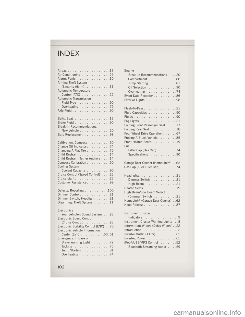
Airbag..................13
Air Conditioning............25
Alarm, Panic ..............10
Arming Theft System (Security Alarm) ...........11
Automatic Temperature Control (ATC) ............25
Automatic Transmission FluidType .............90
Overheating ............75
AxleFluid................90
Belts, Seat ...............12
BrakeFluid...............90
Break-In Recommendations, New Vehicle .............20
Bulb Replacement ...........98
Calibration, Compass .........60
Change Oil Indicator ..........74
Changing A Flat Tire ..........75
Child Restraint .............14
Child Restraint Tether Anchors ....14
Compass Calibration ..........60
Cooling System Coolant Capacity ..........90
Cruise Control (Speed Control) ....23
CruiseLight...............23
Customer Assistance ..........99
Defects, Reporting ..........100
Dimmer Control .............21
Dimmer Switch, Headlight ......21
Disarming, Theft System .......11
Electronics Your Vehicle's Sound System . . .28
Electronic Speed Control (Cruise Control) ...........23
Electronic Stability Control (ESC) . .70
Electronic Vehicle Information Center(EVIC)..........60,61
Emergency, In Case of Brake Warning Light .......72
Jacking ...............75
Jump Starting ...........81
Overheating ............74 Engine
Break-In Recommendations . . .20
Compartment ...........88
Jump Starting ...........81
Oil Selection ............90
Overheating ............74
Event Data Recorder ..........86
Exterior Lights .............98
Flash-To-Pass ..............21
Fluid Capacities ............90
Fluids ..................90
FogLights................21
FoldingFrontPassengerSeat.....17
FoldingRearSeat ...........18
Four Wheel Drive Operation ......67
Freeing A Stuck Vehicle ........85
Front Heated Seats ...........19
Fuel Filler Cap (Gas Cap) ........74
Specifications ...........90
Garage Door Opener (HomeLink
®) . .62
Gas Cap (Fuel Filler Cap) .......74
Headlights ................21
Dimmer Switch ..........21
HighBeam .............21
Heated Seats ..............19
High Beam/Low Beam Select (Dimmer) Switch ..........21
HomeLink
®(Garage Door Opener) . .62
Hood Release ..............87
Instrument Cluster Indicators ..............9
Instrument Cluster Warning Lights . . .8
Intermittent Wipers (Delay Wipers) . .22
Introduction ...............2
Inverter Outlet (115V) .........65
Inverter, Power .............65
iPod
®/USB/MP3 Control ........52
Bluetooth Streaming Audio ....59
INDEX
102
Page 107 of 116
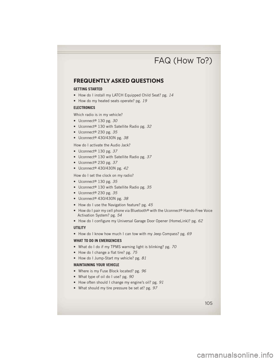
FREQUENTLY ASKED QUESTIONS
GETTING STARTED
• How do I install my LATCH Equipped Child Seat? pg.14
• How do my heated seats operate? pg. 19
ELECTRONICS
Which radio is in my vehicle?
• Uconnect
®130 pg. 30
• Uconnect
®130 with Satellite Radio pg. 32
• Uconnect
®230 pg. 35
• Uconnect
®430/430N pg. 38
How do I activate the Audio Jack?
• Uconnect
®130 pg. 37
• Uconnect
®130 with Satellite Radio pg. 37
• Uconnect
®230 pg. 37
• Uconnect
®430/430N pg. 42
How do I set the clock on my radio?
• Uconnect
®130 pg. 35
• Uconnect
®130 with Satellite Radio pg. 35
• Uconnect
®230 pg. 35
• Uconnect
®430/430N pg. 38
• How do I use the Navigation feature? pg. 45
• How do I pair my cell phone via Bluetooth
®with the Uconnect®Hands-Free Voice
Activation System? pg. 54
• How do I configure my Universal Garage Door Opener (HomeLink)? pg. 62
UTILITY
• How do I know how much I can tow with my Jeep Compass? pg. 69
WHAT TO DO IN EMERGENCIES
• What do I do if my TPMS warning light is blinking? pg. 70
• How do I change a flat tire? pg. 75
• How do I Jump-Start my vehicle? pg. 81
MAINTAINING YOUR VEHICLE
• Where is my Fuse Block located? pg. 96
• What type of oil do I use? pg. 90
• How often should I change my engine’s oil? pg. 91
• What should my tire pressure be set at? pg. 97
FAQ (How To?)
105