engine JEEP COMPASS 2019 Owner handbook (in English)
[x] Cancel search | Manufacturer: JEEP, Model Year: 2019, Model line: COMPASS, Model: JEEP COMPASS 2019Pages: 362, PDF Size: 6.23 MB
Page 31 of 362
Front Ventilated Seats — If Equipped
If your vehicle is equipped with ventilated
seats, the seat cushion and seat back will
have fans that draw the air from the passen-
ger compartment and move air through fine
perforations in the seat cover to help keep the
driver and front passenger cooler in higher
ambient temperatures. The fans operate at
two speeds, HI and LO.
The front ventilated seats control buttons are
located within the Uconnect system. You can
gain access to the control buttons through
the climate screen or the controls screen.
• Press the ventilated seat button
once
to choose HI.
• Press the ventilated seat button
a
second time to choose LO.
• Press the ventilated seat button
a third
time to turn the ventilated seat OFF.
NOTE:
The engine must be running for the ventilated
seats to operate.Vehicles With Remote Start — If Equipped
On models that are equipped with remote
start, the ventilated seats can be pro-
grammed to come on during a remote start.
This feature can be programmed through the
Uconnect system. Refer to your Owner's
Manual for further details.
40/20/40 Rear Seat Armrest— If Equipped
The center part of the rear seat can also be
used as a rear armrest with cup holders, pull
the rear armrest tab to release it from the seat
and pull forward.
WARNING!
Be certain that the seatback is securely
locked into position. If the seatback is not
securely locked into position the seat will
not provide the proper stability for child
seats and/or passengers. An improperly
latched seat could cause serious injury.
HEAD RESTRAINTS
Head restraints are designed to reduce the
risk of injury by restricting head movement in
the event of a rear impact. Head restraints
should be adjusted so that the top of the head
restraint is located above the top of your ear.
WARNING!
• All occupants, including the driver,
should not operate a vehicle or sit in a
vehicle’s seat until the head restraints
are placed in their proper positions in
order to minimize the risk of neck injury
in the event of a crash.
• Head restraints should never be ad-
justed while the vehicle is in motion.
Driving a vehicle with the head restraints
improperly adjusted or removed could
cause serious injury or death in the event
of a collision.
NOTE:
Do not reverse the head restraints (making
the rear of the head restraint face forward) in
an attempt to gain additional clearance to the
back of your head.
29
Page 34 of 362
STEERING WHEEL
Tilt/Telescoping Steering Column
This feature allows you to tilt the steering
column upward or downward. It also allows
you to lengthen or shorten the steering col-
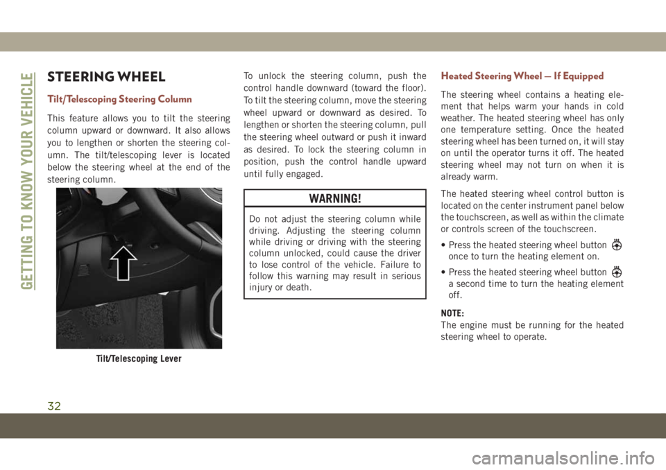
umn. The tilt/telescoping lever is located
below the steering wheel at the end of the
steering column.To unlock the steering column, push the
control handle downward (toward the floor).
To tilt the steering column, move the steering
wheel upward or downward as desired. To
lengthen or shorten the steering column, pull
the steering wheel outward or push it inward
as desired. To lock the steering column in
position, push the control handle upward
until fully engaged.
WARNING!
Do not adjust the steering column while
driving. Adjusting the steering column
while driving or driving with the steering
column unlocked, could cause the driver
to lose control of the vehicle. Failure to
follow this warning may result in serious
injury or death.
Heated Steering Wheel — If Equipped
The steering wheel contains a heating ele-
ment that helps warm your hands in cold
weather. The heated steering wheel has only
one temperature setting. Once the heated
steering wheel has been turned on, it will stay
on until the operator turns it off. The heated
steering wheel may not turn on when it is
already warm.
The heated steering wheel control button is
located on the center instrument panel below
the touchscreen, as well as within the climate
or controls screen of the touchscreen.
• Press the heated steering wheel button
once to turn the heating element on.
• Press the heated steering wheel button
a second time to turn the heating element
off.
NOTE:
The engine must be running for the heated
steering wheel to operate.
Tilt/Telescoping Lever
GETTING TO KNOW YOUR VEHICLE
32
Page 36 of 362
Rotate the headlight switch clockwise to the
first detent for parking light and instrument
panel light operation. Rotate the headlight
switch to the second detent for headlight,
parking light and instrument panel light op-
eration.
Daytime Running Lights (DRL) —
If Equipped
The Daytime Running Lights will turn on
when the engine is started and remain on
unless the headlamps are turned on or the
ignition is turned OFF.
NOTE:
If allowed by law in the country in which the
vehicle was purchased the Daytime Running
Lights can be turned on and off using the
Uconnect System. Refer to “Uconnect Set-
tings” in “Multimedia” in the Owner’s
Manual for further details.
High/Low Beam Switch
Push the multifunction lever toward the in-
strument panel to switch the headlights to
high beams. Pulling the multifunction lever
back toward the steering wheel will return the
lights to low beams.
Automatic High Beam Headlamp Control
— If Equipped
The Automatic High Beam Headlamp Control
system provides increased forward lighting at
night by automating high beam control
through the use of a digital camera mounted
on the inside rearview mirror. This camera
detects vehicle specific light and automati-
cally switches from high beams to low beams
until the approaching vehicle is out of view.
NOTE:
• The Automatic High Beam Headlamp Con-
trol can be turned on or off using the
Uconnect System. Refer to “Uconnect Set-
tings” in “Multimedia” in the Owner’s
Manual for further information.• Broken, muddy, or obstructed headlights
and taillights of vehicles in the field of view
will cause headlights to remain on longer
(closer to the vehicle). Also, dirt, film, and
other obstructions on the windshield or
camera lens will cause the system to func-
tion improperly.
Flash-To-Pass
You can signal another vehicle with your
headlights by lightly pulling the multifunc-
tion lever toward you. This will cause the high
beam headlights to turn on, and remain on,
until the lever is released.
Automatic Headlights — If Equipped
This system automatically turns the head-
lights on or off according to ambient light
levels. To turn the system on, rotate the
headlight switch clockwise to the last detent
for automatic headlight operation. When the
system is on, the headlight time delay feature
is also on. This means the headlights will stay
on for up to 90 seconds after you place the
ignition into the OFF position. To turn the
automatic system off, move the headlight
switch out of the AUTO position.
GETTING TO KNOW YOUR VEHICLE
34
Page 37 of 362
NOTE:
The engine must be running before the head-
lights will come on in the automatic mode.
Headlight Time Delay
This feature provides the safety of headlight
illumination for up to 90 seconds (program-
mable) when leaving your vehicle in an unlit
area.
To activate the delay feature, place the igni-
tion in the OFF position while the headlights
are still on. Then, turn off the headlights
within 45 seconds. The delay interval begins
when the headlight switch is turned off.
If you turn the headlights or parking lights on,
or place the ignition in ACC or RUN, the
system will cancel the delay.
If you turn the headlights off before the
ignition, they will turn off in the normal
manner.NOTE:
• The lights must be turned off within 45 sec-
onds of placing the ignition in the OFF
position to activate this feature. If the
headlight switch is in the AUTO position
prior to turning the ignition OFF, there is no
need to turn the headlight switch to off to
activate Headlight Delay.
• The headlight delay time is programmable
using the Uconnect System. Refer to
“Uconnect Settings” in “Multimedia” in
the Owner’s Manual for further details.
Lights-On Reminder — If Equipped
If the headlights or parking lights are on after
the ignition is in the OFF position, a chime
will sound to alert the driver when the driver's
door is opened.
NOTE:
Leaving the headlights, or parking lights, on
after the ignition is in the OFF position (when
the vehicle is not equipped with the
Lights-On Reminder feature) may result in
vehicle battery discharge.
Front And Rear Fog Lights — If Equipped
The fog light switches are built into the head-
light switch.
To activate the front fog lights, push the
upper half of the headlight switch. To turn off
the front fog lights, push the upper half of the
headlight switch a second time.
NOTE:
To activate the front fog lights, the parking
lights or low beam headlights must first be
activated.
To activate the rear fog lights, push the lower
half of the headlight switch. To turn off the
rear fog lights, push the lower half of the
headlight switch a second time.
NOTE:
To turn on the rear fog lights, the low beam
headlights or front fog lights must first be
active. If the vehicle is only equipped with
rear fog lights, only a single button will be
available in the center of the headlight
switch. Push once to turn the rear fog lights
on, and a second time to turn them off.
35
Page 49 of 362
Automatic Temperature Control (ATC)
Automatic Operation
1. Push the AUTO button on the faceplate,
or the AUTO button on the touchscreen (if
equipped) on the Automatic Temperature
Control (ATC) Panel.
2. Next, adjust the temperature you would
like the system to maintain by adjusting
the temperature control buttons. Once the
desired temperature is displayed, the sys-
tem achieves and automatically maintains
that comfort level.
3. When the system is set up for your comfort
level, it is not necessary to change the
settings. You experience the greatest effi-
ciency by simply allowing the system to
function automatically.
NOTE:
• It is not necessary to move the temperature
settings for cold or hot vehicles. The system
automatically adjusts the temperature,
mode, and blower speed to provide comfort
as quickly as possible.• The temperature can be displayed in U.S.
or Metric units by selecting the US/Metric
customer-programmable feature.
To provide you with maximum comfort in the
Automatic mode during cold start-ups, the
blower fan remains on low until the engine
warms up. The blower increases in speed and
transition into Auto mode.
Manual Operation Override
This system offers a full complement of
manual override features. The AUTO symbol
in the front ATC display will be turned off
when the system is being used in the manual
mode.
Operating Tips
Summer Operation
The engine cooling system must be protected
with a high-quality antifreeze coolant to pro-
vide proper corrosion protection and to pro-
tect against engine overheating. OAT coolant
(conforming to MS.90032) is recommended.
Winter Operation
To ensure the best possible heater and de-
froster performance, make sure the engine
cooling system is functioning properly and
the proper amount, type, and concentration
of coolant is used. Use of the Air Recircula-
tion mode during Winter months is not rec-
ommended, because it may cause window
fogging.
Vacation/Storage
Before you store your vehicle, or keep it out of
service (i.e., vacation) for two weeks or more,
run the air conditioning system at idle for
about five minutes, in fresh air with the
blower setting on high. This will ensure ad-
equate system lubrication to minimize the
possibility of compressor damage when the
system is started again.
Window Fogging
Vehicle windows tend to fog on the inside in
mild, rainy, and/or humid weather. To clear
the windows, select Defrost or Mix mode and
increase the front blower speed. Do not use
the Recirculation mode without A/C for long
periods, as fogging may occur.
47
Page 59 of 362
CAUTION!
of the power outlet can cause damage not
covered by your New Vehicle Limited War-
ranty.
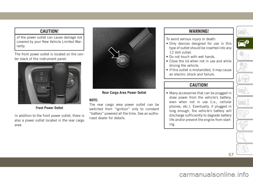
The front power outlet is located on the cen-
ter stack of the instrument panel.
In addition to the front power outlet, there is
also a power outlet located in the rear cargo
area.NOTE:
The rear cargo area power outlet can be
switched from “ignition” only to constant
“battery” powered all the time. See an autho-
rized dealer for details.
WARNING!
To avoid serious injury or death:
• Only devices designed for use in this
type of outlet should be inserted into any
12 Volt outlet.
• Do not touch with wet hands.
• Close the lid when not in use and while
driving the vehicle.
• If this outlet is mishandled, it may cause
an electric shock and failure.
CAUTION!
• Many accessories that can be plugged in
draw power from the vehicle's battery,
even when not in use (i.e., cellular
phones, etc.). Eventually, if plugged in
long enough, the vehicle's battery will
discharge sufficiently to degrade battery
life and/or prevent the engine from start-
ing.
Front Power Outlet
Rear Cargo Area Power Outlet
57
Page 63 of 362
•Down Arrow Button
Push and release thedownarrow button to
scroll downward through the main menu
and submenus.
•Right Arrow Button
Push and release therightarrow button to
access the information screens or submenu
screens of a main menu item.
•Left Arrow Button
Push and release theleftarrow button to
access the information screens or submenu
screens of a main menu item.
•OK Button
Push theOKbutton to access/select the
information screens or submenu screens of
a main menu item. Push and hold theOK
button for one second to reset displayed/
selected features that can be reset.Oil Change Indicator System —
If Equipped
Your vehicle is equipped with an engine oil
change indicator system. The “Oil Change
Due” message will display in the instrument
cluster display for five seconds after a single
chime has sounded, to indicate the next
scheduled oil change interval. The engine oil
change indicator system is duty cycle based,
which means the engine oil change interval
may fluctuate, dependent upon your personal
driving style.
Gear Shift Indicator (GSI) — If Equipped
The Gear Shift Indicator (GSI) system is en-
abled on vehicles with a manual transmis-
sion, or when a vehicle with an automatic
transmission is in manual shift mode. The
GSI provides the driver with a visual indica-
tion when the recommended gear shift point
has been reached. This indication notifies
the driver that changing gear will allow a
reduction in fuel consumption. When the up
shift indicator is shown on the instrument
cluster display, the GSI is advising the driver
to engage a higher gear. When the down shift
indicator is shown on the display, the GSI is
advising the driver to engage a lower gear.
The GSI indicator remains illuminated until
the driver changes gear, or the driving condi-
tions return to a situation where changing
gear is not required to improve fuel consump-
tion.
61
Page 65 of 362
MESSAGE DESCRIPTION
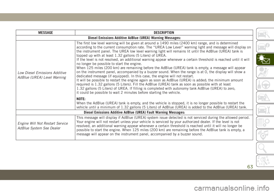
Diesel Emissions Additive AdBlue (UREA) Warning Messages:
Low Diesel Emissions Additive
AdBlue (UREA) Level WarningThe first low level warning will be given at around a 1490 miles (2400 km) range, and is determined
according to the current consumption rate. The “UREA Low Level” warning light and message will display on
the instrument panel. The UREA low level warning light will remains lit until the AdBlue (UREA) tank is
topped up with at least 1.32 gallons (5 Liters) of UREA.
If the level is not resolved, an additional warning appear whenever a certain threshold is reached until it will
no longer be possible to start the engine.
When 125 miles (200 km) are remaining before the AdBlue (UREA) tank is empty, a message will appear
on the instrument panel, accompanied by a buzzer sound. When the range is at 0, the display will show a
dedicated message (if equipped). In this case, the engine will not restart.
It will be possible to restart the engine again as soon as AdBlue (UREA) is added; the minimum amount
required is 1.32 gallons (5 Liters). Fill the AdBlue (UREA) tank as soon as possible with at least
1.32 gallons (5 Liters) of UREA. If filling is completed with autonomy tank AdBlue (UREA) to zero,
it could be possible to wait 2 minutes before starting the vehicle.
NOTE:
When the AdBlue (UREA) tank is empty, and the vehicle is stopped, it is no longer possible to restart the
vehicle until a minimum of 1.32 gallons (5 Liters) of AdBlue (UREA) is added to the AdBlue (UREA) tank.
Diesel Emissions Additive AdBlue (UREA) Fault Warning Messages:
Engine Will Not Restart Service
AdBlue System See DealerThis message will display if AdBlue (UREA) system issue detected is not serviced during the allowed period.
Your engine will not restart unless your vehicle is serviced by your authorized dealer. If the level is not
resolved, an additional warning appear whenever a certain threshold is reached until it will no longer be
possible to start the engine. When 125 miles (200 km) are remaining before the AdBlue tank is empty, a
message will appear on the instrument panel, accompanied by a buzzer sound.
63
Page 66 of 362
MESSAGE DESCRIPTION
Engine Will Not Start Service
AdBlue System See DealerNOTE:
• The display may take up to five seconds to update after adding 2 gallons (7.5 Liters) or more of AdBlue
(UREA) to the AdBlue (UREA) tank. If you have a fault related to the AdBlue (UREA) system, the display
may not update to the new level. See an authorized dealer for service.
• AdBlue freezes at temperatures lower than 12°F (-11°C). If the car stands for a long time at this
temperature, refilling could be difficult. For this reason, it is advised to park the vehicle in a garage
and/or heated environment, and wait for the AdBlue (UREA) to return to liquid state before topping up.
TRIP COMPUTER
Push and release the up or down arrow button
until the Trip A or Trip B icon is highlighted in
the instrument cluster display (Toggle left or
right to select Trip A or Trip B). Push and
release the OK button to display the Trip
information.
WARNING LIGHTS
AND MESSAGES
The warning/indicator lights will illuminate in
the instrument panel together with a dedi-
cated message and/or acoustic signal when
applicable. These indications are indicative
and precautionary and as such must not be
considered as exhaustive and/or alternative
to the information contained in the Owner’s
Manual, which you are advised to read care-
fully in all cases. Always refer to the informa-
tion in this chapter in the event of a failure
indication. All active telltales will display first
if applicable. The system check menu may
appear different based upon equipment op-
tions and current vehicle status. Some tell-
tales are optional and may not appear.
Red Warning Lights
— Air Bag Warning Light
This warning light will illuminate to indicate
a fault with the air bag, and will turn on for
four to eight seconds as a bulb check when
the ignition is placed in the ON/RUN or
ACC/ON/RUN position. This light will illumi-
nate with a single chime when a fault with the
air bag has been detected, it will stay on until
the fault is cleared. If the light is either not on
during startup, stays on, or turns on while
driving, have the system inspected at an
authorized dealer as soon as possible.
GETTING TO KNOW YOUR INSTRUMENT PANEL
64
Page 68 of 362
— Battery Charge Warning Light
This warning light will illuminate when the
battery is not charging properly. If it stays on
while the engine is running, there may be a
malfunction with the charging system. Con-
tact an authorized dealer as soon as possible.
This indicates a possible problem with the
electrical system or a related component.
— Door Open Warning Light
This indicator will illuminate when a door is
ajar/open and not fully closed.
NOTE:
If the vehicle is moving, there will also be a
single chime.
— Electric Power Steering Fault
Warning Light
This warning light will turn on when there's a
fault with the EPS (Electric Power Steering)
system. Refer to “Power Steering” in “Start-
ing And Operating” in the Owner’s Manual for
further information.
WARNING!
Continued operation with reduced assist
could pose a safety risk to yourself and
others. Service should be obtained as soon
as possible.
— Electronic Throttle Control (ETC)
Warning Light
This warning light will illuminate to indicate
a problem with the Electronic Throttle Con-
trol (ETC) system. If a problem is detected
while the vehicle is running, the light will
either stay on or flash depending on the
nature of the problem. Cycle the ignition
when the vehicle is safely and completely
stopped and the transmission is placed in the
PARK position. The light should turn off. If
the light remains on with the vehicle running,
your vehicle will usually be drivable; however,
see an authorized dealer for service as soon
as possible.
NOTE:
This light may turn on if the accelerator and
brake pedals are pressed at the same time.If the light continues to flash when the ve-
hicle is running, immediate service is re-
quired and you may experience reduced per-
formance, an elevated/rough idle, or engine
stall and your vehicle may require towing.
The light will come on when the ignition is
placed in the ON/RUN or ACC/ON/RUN posi-
tion and remain on briefly as a bulb check. If
the light does not come on during starting,
have the system checked by an authorized
dealer.
— Engine Temperature Warning Light
This warning light will illuminate to warn of
an overheated engine condition. If the engine
coolant temperature is too high, this light will
illuminate and a single chime will sound.
If the light turns on while driving, safely pull
over and stop the vehicle. If the A/C system is
on, turn it off. Also, shift the transmission
into NEUTRAL and idle the vehicle. If the
temperature reading does not return to nor-
mal, turn the engine off immediately and call
for service.
Refer to “If Your Engine Overheats” in “In
Case Of Emergency” for further information.
GETTING TO KNOW YOUR INSTRUMENT PANEL
66