turn signal JEEP COMPASS 2019 Owner handbook (in English)
[x] Cancel search | Manufacturer: JEEP, Model Year: 2019, Model line: COMPASS, Model: JEEP COMPASS 2019Pages: 362, PDF Size: 6.23 MB
Page 76 of 362
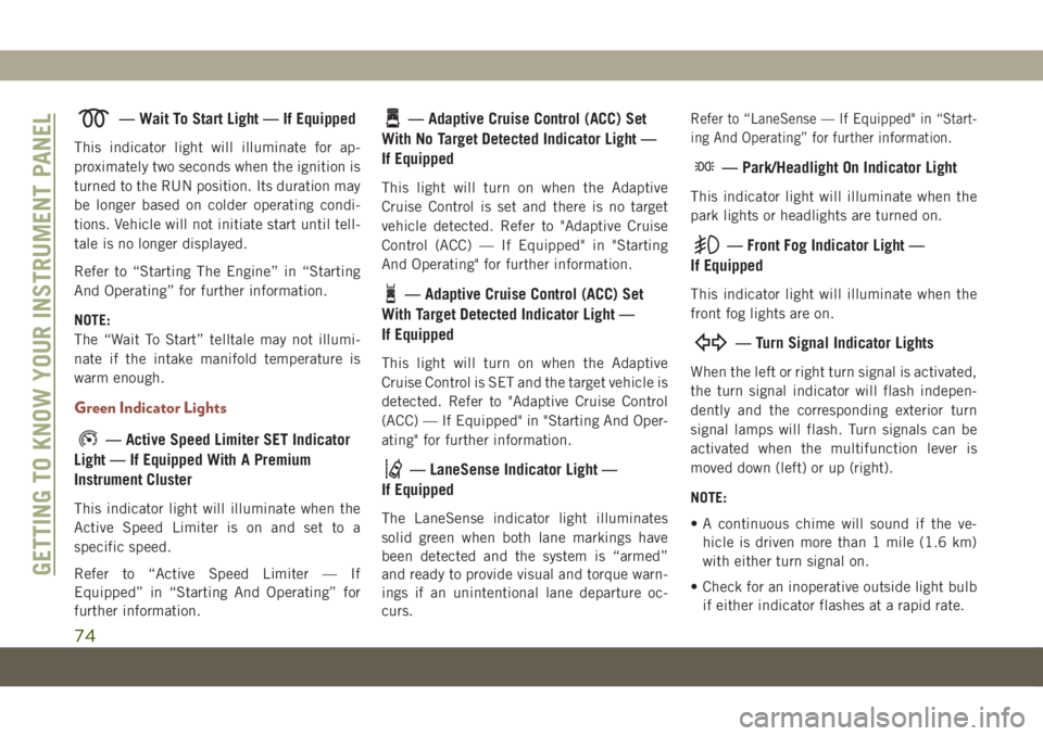
— Wait To Start Light — If Equipped
This indicator light will illuminate for ap-
proximately two seconds when the ignition is
turned to the RUN position. Its duration may
be longer based on colder operating condi-
tions. Vehicle will not initiate start until tell-
tale is no longer displayed.
Refer to “Starting The Engine” in “Starting
And Operating” for further information.
NOTE:
The “Wait To Start” telltale may not illumi-
nate if the intake manifold temperature is
warm enough.
Green Indicator Lights
— Active Speed Limiter SET Indicator
Light — If Equipped With A Premium
Instrument Cluster
This indicator light will illuminate when the
Active Speed Limiter is on and set to a
specific speed.
Refer to “Active Speed Limiter — If
Equipped” in “Starting And Operating” for
further information.
— Adaptive Cruise Control (ACC) Set
With No Target Detected Indicator Light —
If Equipped
This light will turn on when the Adaptive
Cruise Control is set and there is no target
vehicle detected. Refer to "Adaptive Cruise
Control (ACC) — If Equipped" in "Starting
And Operating" for further information.
— Adaptive Cruise Control (ACC) Set
With Target Detected Indicator Light —
If Equipped
This light will turn on when the Adaptive
Cruise Control is SET and the target vehicle is
detected. Refer to "Adaptive Cruise Control
(ACC) — If Equipped" in "Starting And Oper-
ating" for further information.
— LaneSense Indicator Light —
If Equipped
The LaneSense indicator light illuminates
solid green when both lane markings have
been detected and the system is “armed”
and ready to provide visual and torque warn-
ings if an unintentional lane departure oc-
curs.
Refer to “LaneSense — If Equipped" in “Start-
ing And Operating” for further information.
— Park/Headlight On Indicator Light
This indicator light will illuminate when the
park lights or headlights are turned on.
— Front Fog Indicator Light —
If Equipped
This indicator light will illuminate when the
front fog lights are on.
— Turn Signal Indicator Lights
When the left or right turn signal is activated,
the turn signal indicator will flash indepen-
dently and the corresponding exterior turn
signal lamps will flash. Turn signals can be
activated when the multifunction lever is
moved down (left) or up (right).
NOTE:
• A continuous chime will sound if the ve-
hicle is driven more than 1 mile (1.6 km)
with either turn signal on.
• Check for an inoperative outside light bulb
if either indicator flashes at a rapid rate.
GETTING TO KNOW YOUR INSTRUMENT PANEL
74
Page 91 of 362
when the vehicle speed reaches approxi-
mately 6 mph (10 km/h) or higher and will
alert the driver of vehicles in these areas.
NOTE:
• The BSM system does NOT alert the driver
about rapidly approaching vehicles that are
outside the detection zones.
• The BSM system detection zone DOES NOT
change if your vehicle is towing a trailer.
Therefore, visually verify the adjacent lane
is clear for both your vehicle and trailer
before making a lane change. If the trailer
or other object (i.e., bicycle, sports equip-
ment) extends beyond the side of your ve-
hicle, this may result in the BSM warning
light remaining illuminated the entire time
the vehicle is in a forward gear. It may be
necessary to deactivate the BSM system
manually to avoid miss-detection. Refer to
“Uconnect Settings” in “Multimedia” in
the Owner’s Manual for further information.• The Blind Spot Monitoring (BSM) system
may experience drop outs (blinking on and
off) of the side mirror Warning Indicator
lamps when a motorcycle or any small ob-
ject remains at the side of the vehicle for
extended periods of time (more than a
couple of seconds).
The area on the rear fascia where the radar
sensors are located must remain free of snow,
ice, and dirt/road contamination so that the
BSM system can function properly. Do not
block the area of the rear fascia where the
radar sensors are located with foreign objects
(bumper stickers, bicycle racks, etc.)
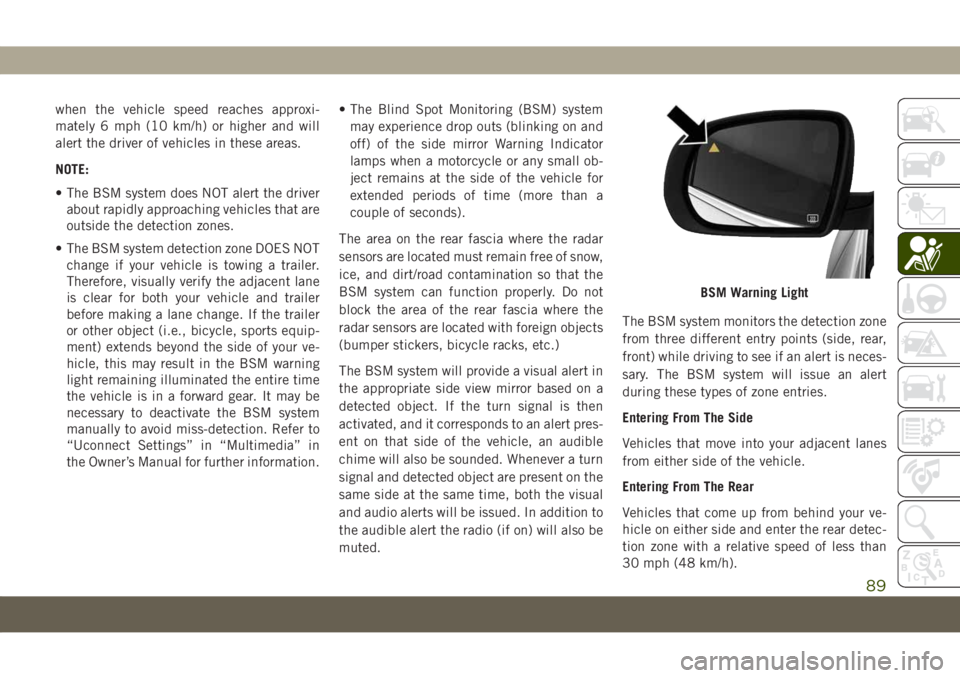
The BSM system will provide a visual alert in
the appropriate side view mirror based on a
detected object. If the turn signal is then
activated, and it corresponds to an alert pres-
ent on that side of the vehicle, an audible
chime will also be sounded. Whenever a turn
signal and detected object are present on the
same side at the same time, both the visual
and audio alerts will be issued. In addition to
the audible alert the radio (if on) will also be
muted.The BSM system monitors the detection zone
from three different entry points (side, rear,
front) while driving to see if an alert is neces-
sary. The BSM system will issue an alert
during these types of zone entries.
Entering From The Side
Vehicles that move into your adjacent lanes
from either side of the vehicle.
Entering From The Rear
Vehicles that come up from behind your ve-
hicle on either side and enter the rear detec-
tion zone with a relative speed of less than
30 mph (48 km/h).
BSM Warning Light
89
Page 92 of 362
Overtaking Traffic
If you pass another vehicle slowly with a
relative speed less than 10 mph (16 km/h)
and the vehicle remains in the blind spot for
approximately 1.5 seconds, the warning light
will be illuminated. If the difference in speed
between the two vehicles is greater than
10 mph (16 km/h), the warning light will not
illuminate.
The BSM system is designed not to issue an
alert on stationary objects such as guardrails,
posts, walls, foliage, berms, etc. However,
occasionally the system may alert on such
objects. This is normal operation and your
vehicle does not require service.
The BSM system will not alert you of objects
that are traveling in the opposite direction of
the vehicle in adjacent lanes.
NOTE:
The BSM system may experience drop outs
(blinking on and off) in the side mirror LED
icons while a motorcycle, or any small target,
remains at the vehicle’s B-pillar for an ex-
tended period of time (longer than a couple of
seconds).WARNING!
The Blind Spot Monitoring system is only
an aid to help detect objects in the blind
spot zones. The BSM system is not de-
signed to detect pedestrians, bicyclists, or
animals. Even if your vehicle is equipped
with the BSM system, always check your
vehicle’s mirrors, glance over your shoul-
der, and use your turn signal before chang-
ing lanes. Failure to do so can result in
serious injury or death.
Rear Cross Path (RCP)
The Rear Cross Path (RCP) feature is in-
tended to aid the driver when backing out of
parking spaces where their vision of oncom-
ing vehicles may be blocked. Proceed slowly
and cautiously out of the parking space until
the rear end of the vehicle is exposed. The
RCP system will then have a clear view of the
cross traffic and if an oncoming vehicle is
detected, alert the driver.
RCP monitors the rear detection zones on
both sides of the vehicle, for objects that are
moving toward the side of the vehicle with a
minimum speed of approximately 3 mph(5 km/h), to objects moving a maximum of
approximately 20 mph (32 km/h), such as in
parking lot situations.
NOTE:
In a parking lot situation, oncoming vehicles
can be obscured by vehicles parked on either
side. If the sensors are blocked by other
structures or vehicles, the system will not be
able to alert the driver.
When RCP is on and the vehicle is in RE-
VERSE, the driver is alerted using both the
visual and audible alarms, including reduc-
ing the radio volume.
WARNING!
Rear Cross Path Detection (RCP) is not a
back up aid system. It is intended to be
used to help a driver detect an oncoming
vehicle in a parking lot situation. Drivers
must be careful when backing up, even
when using RCP. Always check carefully
behind your vehicle, look behind you, and
be sure to check for pedestrians, animals,
other vehicles, obstructions, and blind
spots before backing up. Failure to do so
can result in serious injury or death.
SAFETY
90
Page 93 of 362
Modes Of Operation
Three selectable modes of operation are
available in the Uconnect System. Refer to
“Uconnect Settings” in “Multimedia” in the
Owner’s Manual for further information.
Blind Spot Alert Lights Only (Default Setting)
When operating in Blind Spot Alert mode, the
BSM system will provide a visual alert in the
appropriate side view mirror based on a de-
tected object. However, when the system is
operating in Rear Cross Path (RCP) mode, the
system will respond with both visual and
audible alerts when a detected object is pres-
ent. Whenever an audible alert is requested,
the radio is muted.
Blind Spot Alert Lights/Chime
When operating in Blind Spot Alert Lights/
Chime mode, the BSM system will provide a
visual alert in the appropriate side view mirror
based on a detected object. If the turn signal
is then activated, and it corresponds to an
alert present on that side of the vehicle, an
audible chime will also be sounded. When-
ever a turn signal and detected object are
present on the same side at the same time,both the visual and audible alerts will be
issued. In addition to the audible alert the
radio (if on) will also be muted.
NOTE:
Whenever an audible alert is requested by the
BSM system, the radio is also muted.
When the system is in RCP, the system shall
respond with both visual and audible alerts
when a detected object is present. Whenever
an audible alert is requested, the radio vol-
ume is reduced. Turn/hazard signal status is
ignored; the RCP state always requests the
chime.
Blind Spot Alert Off
When the BSM system is turned off there will
be no visual or audible alerts from either the
BSM or RCP systems.
NOTE:
The BSM system will store the current oper-
ating mode when the vehicle is shut off. Each
time the vehicle is started the previously
stored mode will be recalled and used.Blocked Sensor
If the system detects degraded performance
due to contamination or foreign objects, a
message will warn you of a blocked sensor
and the warning indicators in side view mir-
rors will be illuminated. The warning indica-
tors will remain illuminated until blockage
clearing conditions are met. First clear the
fascia area around the sensors of the block-
age. After removing the blockage, reset the
system by cycling the ignition from ON to OFF
and then back ON.
Forward Collision Warning (FCW)
With Mitigation — If Equipped
Forward Collision Warning (FCW)
With Mitigation Operation
The Forward Collision Warning (FCW) system
with mitigation provides the driver with au-
dible warnings, visual warnings (within the
instrument cluster display), and may apply a
brake jerk to warn the driver when it detects a
potential frontal collision. The warnings and
limited braking are intended to provide the
driver with enough time to react, avoid or
mitigate the potential collision.
91
Page 98 of 362
Tire Pressure Monitoring Low Pressure
Warnings
The Tire Pressure Monitoring System
Warning Light will illuminate in the
instrument cluster and a chime will
sound when tire pressure is low in one or
more of the four active road tires. In addition,
the instrument cluster will display a "Tire
Low" message and a graphic showing the
pressure values of each tire with the low tire
pressure values highlighted or in a different
color.
Should this occur, you should stop as soon as
possible and inflate the tires with low pres-
sure (those highlighted or in a different color
in the instrument cluster display graphic) to
the vehicle’s recommended cold placard
pressure value. Once the system receives the
updated tire pressures, the system will auto-
matically update, the pressure values in the
graphic display in the instrument cluster will
stop being highlighted or return to their origi-
nal color, and the Tire Pressure Monitoring
System Warning Light will turn off.NOTE:
When filling warm tires, the tire pressure may
need to be increased up to an additional 4 psi
(28 kPa) above the recommended cold plac-
ard pressure in order to turn the Tire Pressure
Monitoring System Warning Light off. The
vehicle may need to be driven for up to
10 minutes above 15 mph (24 km/h) in order
for the TPMS to receive this information.
Service TPMS Warning
When a system fault is detected, the Tire
Pressure Monitoring System Warning Light
will flash on and off for 75 seconds and then
remain on solid. The system fault will also
sound a chime. In addition, the instrument
cluster will display a "SERVICE TPM SYS-
TEM" message for a minimum of five seconds
and then display dashes (- -) in place of the
pressure value to indicate which sensor is not
being received.
If the ignition key is cycled, this sequence
will repeat, providing the system fault still
exists. If the system fault no longer exists, the
Tire Pressure Monitoring System Warning
Light will no longer flash, and the “SERVICE
TPM SYSTEM” message will no longer dis-play, and a pressure value will display in
place of the dashes. A system fault can occur
due to any of the following:
• Jamming due to electronic devices or driv-
ing next to facilities emitting the same
radio frequencies as the TPMS sensors.
• Installing some form of aftermarket window
tinting that affects radio wave signals.
• Lots of snow or ice around the wheels or
wheel housings.
• Using tire chains on the vehicle.
• Using wheels/tires not equipped with
TPMS sensors.
Vehicles With Compact Spare or Non-Matching
Full Size Spare
1. The compact spare tire or non-matching
full size does not have a tire pressure
monitoring sensor. Therefore, the TPMS
will not monitor the pressure in the com-
pact or non-matching full size spare tire.
2. If you install the compact or non-
matching full size spare tire in place of a
road tire that has a pressure below the
low-pressure warning limit, upon the next
ignition key cycle, the Tire Pressure Moni-
SAFETY
96
Page 101 of 362
8. Do not lean against the door or window. If
your vehicle has side air bags, and deploy-
ment occurs, the side air bags will inflate
forcefully into the space between occu-
pants and the door and occupants could
be injured.
9. If the air bag system in this vehicle needs
to be modified to accommodate a dis-
abled person, refer to the “Customer As-
sistance” section for customer service
contact information.
WARNING!
• NEVER use a rearward facing child re-
straint on a seat protected by an ACTIVE
AIRBAG in front of it, DEATH or SERI-
OUS INJURY to the CHILD can occur.
• It is advisable to always carry children in
a child restraint system on the rear seat,
which is the most protected position in
the event of a collision.
• Should it be necessary to carry a child on
the passenger side front seat in a rear-
facing child restraint system, the pas-
senger side front air bag must be deac-
WARNING!
tivated. Always make sure the airbag
deactivation indicator light is illumi-
nated when using a child restraint sys-
tem. The passenger seat must also be
positioned backward as far as possible to
avoid the child restraint system from
coming into contact with the dashboard.
• A deploying passenger front air bag can
cause death or serious injury to a child
12 years or younger, including a child in
a rear-facing child restraint.
Seat Belt Systems
Buckle up even though you are an excellent
driver, even on short trips. Someone on the
road may be a poor driver and could cause a
collision that includes you. This can happen
far away from home or on your own street.
Research has shown that seat belts save
lives, and they can reduce the seriousness of
injuries in a collision. Some of the worst
injuries happen when people are thrown from
the vehicle. Seat belts reduce the possibilityof ejection and the risk of injury caused by
striking the inside of the vehicle. Everyone in
a motor vehicle should be belted at all times.
Enhanced Seat Belt Use Reminder System
(BeltAlert)
Driver and Passenger BeltAlert (if equipped)
BeltAlert is a feature intended to remind
the driver and outboard front seat passenger
(if equipped with outboard front passenger
seat BeltAlert) to buckle their seat belts. The
Belt Alert feature is active whenever the igni-
tion switch is in the START or ON/RUN posi-
tion.
Initial Indication
If the driver is unbuckled when the ignition
switch is first in the START or ON/RUN posi-
tion, a chime will signal for a few seconds. If
the driver or outboard front seat passenger (if
equipped with outboard front passenger seat
BeltAlert) is unbuckled when the ignition
switch is first in the START or ON/RUN posi-
tion the Seat Belt Reminder Light will turn on
and remain on until both outboard front seat
99
Page 122 of 362
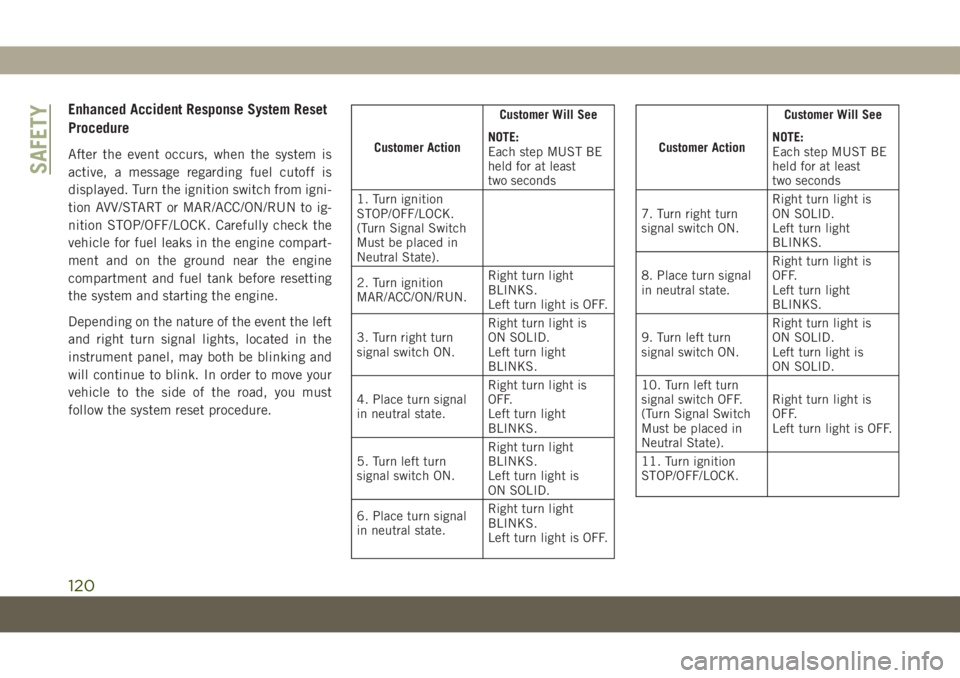
Enhanced Accident Response System Reset
Procedure
After the event occurs, when the system is
active, a message regarding fuel cutoff is
displayed. Turn the ignition switch from igni-
tion AVV/START or MAR/ACC/ON/RUN to ig-
nition STOP/OFF/LOCK. Carefully check the
vehicle for fuel leaks in the engine compart-
ment and on the ground near the engine
compartment and fuel tank before resetting
the system and starting the engine.
Depending on the nature of the event the left
and right turn signal lights, located in the
instrument panel, may both be blinking and
will continue to blink. In order to move your
vehicle to the side of the road, you must
follow the system reset procedure.Customer ActionCustomer Will See
NOTE:
Each step MUST BE
held for at least
two seconds
1. Turn ignition
STOP/OFF/LOCK.
(Turn Signal Switch
Must be placed in
Neutral State).
2. Turn ignition
MAR/ACC/ON/RUN.Right turn light
BLINKS.
Left turn light is OFF.
3. Turn right turn
signal switch ON.Right turn light is
ON SOLID.
Left turn light
BLINKS.
4. Place turn signal
in neutral state.Right turn light is
OFF.
Left turn light
BLINKS.
5. Turn left turn
signal switch ON.Right turn light
BLINKS.
Left turn light is
ON SOLID.
6. Place turn signal
in neutral state.Right turn light
BLINKS.
Left turn light is OFF.Customer ActionCustomer Will See
NOTE:
Each step MUST BE
held for at least
two seconds
7. Turn right turn
signal switch ON.Right turn light is
ON SOLID.
Left turn light
BLINKS.
8. Place turn signal
in neutral state.Right turn light is
OFF.
Left turn light
BLINKS.
9. Turn left turn
signal switch ON.Right turn light is
ON SOLID.
Left turn light is
ON SOLID.
10. Turn left turn
signal switch OFF.
(Turn Signal Switch
Must be placed in
Neutral State).Right turn light is
OFF.
Left turn light is OFF.
11. Turn ignition
STOP/OFF/LOCK.
SAFETY
120
Page 123 of 362
Customer ActionCustomer Will See
NOTE:
Each step MUST BE
held for at least
two seconds
12. Turn ignition
MAR/ACC/ON/RUN.
(Entire sequence
needs to be
completed within
one minute or
sequence will need
to be repeated).System is now reset
and the engine may
be started.
Turn hazard flashers
OFF (Manually).
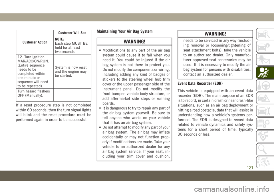
If a reset procedure step is not completed
within 60 seconds, then the turn signal lights
will blink and the reset procedure must be
performed again in order to be successful.
Maintaining Your Air Bag System
WARNING!
• Modifications to any part of the air bag
system could cause it to fail when you
need it. You could be injured if the air
bag system is not there to protect you.
Do not modify the components or wiring,
including adding any kind of badges or
stickers to the steering wheel hub trim
cover or the upper passenger side of the
instrument panel. Do not modify the
front bumper, vehicle body structure, or
add aftermarket side steps or running
boards.
• It is dangerous to try to repair any part of
the air bag system yourself. Be sure to
tell anyone who works on your vehicle
that it has an air bag system.
• Do not attempt to modify any part of your
air bag system. The air bag may inflate
accidentally or may not function prop-
erly if modifications are made. Take your
vehicle to an authorized dealer for any
air bag system service. If your seat, in-
cluding your trim cover and cushion,
WARNING!
needs to be serviced in any way (includ-
ing removal or loosening/tightening of
seat attachment bolts), take the vehicle
to an authorized dealer. Only manufac-
turer approved seat accessories may be
used. If it is necessary to modify the air
bag system for persons with disabilities,
contact an authorized dealer.
Event Data Recorder (EDR)
This vehicle is equipped with an event data
recorder (EDR). The main purpose of an EDR
is to record, in certain crash or near crash-like
situations, such as an air bag deployment or
hitting a road obstacle, data that will assist in
understanding how a vehicle’s systems per-
formed. The EDR is designed to record data
related to vehicle dynamics and safety sys-
tems for a short period of time, typically
30 seconds or less.
121
Page 142 of 362
WARNING!
interference. If your floor mat interferes
with the operation of any pedal, or is not
secure to the floor, remove the floor mat
from the vehicle and place the floor mat
in your trunk.
• ONLY use the passenger’s side floor mat
on the passenger’s side floor area.
• ALWAYS make sure objects cannot fall or
slide into the driver’s side floor area
when the vehicle is moving. Objects can
become trapped under accelerator,
brake, or clutch pedals and could cause
a loss of vehicle control.
• NEVER place any objects under the floor
mat (e.g., towels, keys, etc.). These ob-
jects could change the position of the
floor mat and may cause interference
with the accelerator, brake, or clutch
pedals.
• If the vehicle carpet has been removed
and re-installed, always properly attach
carpet to the floor and check the floor
mat fasteners are secure to the vehicle
WARNING!
carpet. Fully depress each pedal to
check for interference with the accelera-
tor, brake, or clutch pedals then re-
install the floor mats.
• It is recommended to only use mild soap
and water to clean your floor mats. After
cleaning, always check your floor mat
has been properly installed and is se-
cured to your vehicle using the floor mat
fasteners by lightly pulling mat.
Periodic Safety Checks You Should Make
Outside The Vehicle
Tires
Examine tires for excessive tread wear and
uneven wear patterns. Check for stones,
nails, glass, or other objects lodged in the
tread or sidewall. Inspect the tread for cuts
and cracks. Inspect sidewalls for cuts,
cracks, and bulges. Check the wheel nuts for
tightness. Check the tires (including spare)
for proper cold inflation pressure.
Lights
Have someone observe the operation of brake
lights and exterior lights while you work the
controls. Check turn signal and high beam
indicator lights on the instrument panel.
Door Latches
Check for proper closing, latching, and lock-
ing.
Fluid Leaks
Check area under the vehicle after overnight
parking for fuel, coolant, oil, or other fluid
leaks. Also, if gasoline fumes are detected or
if fuel, or brake fluid leaks are suspected. The
cause should be located and corrected imme-
diately.
SAFETY
140
Page 165 of 362
NOTE:
The Active Speed Limiter can be set with the
vehicle stationary, or in motion.
Activation
To activate the feature, push the Active
Speed Limiter button, and a message will
appear along with an indicator light in the
Instrument Cluster Display to signal that Ac-
tive Speed Limiter has been activated.
Push the SET (+) and SET (–) buttons on the
right of the steering wheel to raise and lower
the Active Speed Limiter to the desired value.
Pushing and holding down the SET (+) or SET
(–) buttons will increase/decrease the speed
value by increments of 5 mph (5 km/h).
Each time that Active Speed Limiter is acti-
vated, it will be set to the last programmed
value from the previous activation.
NOTE:
The Speed Control (if equipped) and Adap-
tive Cruise Control (if equipped) features will
be unavailable while the Active Speed Lim-
iter is in use.
Exceeding The Set Speed
By fully pressing the accelerator pedal, the
programmed maximum speed can be ex-
ceeded while the device is active.
In the event that the Active Speed Limiter set
value is exceeded manually with a driver
acceleration, an audible indicator will sound,
the indicator light will rapidly flash, and a
message will appear in the instrument cluster
display.
The feature will remain disabled until the
vehicle speed drops below the set Active
Speed Limiter value, where it will reactivate
automatically.
Deactivation
To turn off Active Speed Limiter, push the
Active Speed Limiter button on the right side
of the steering wheel. A message will appear
in the instrument cluster display to confirm
that the feature has been turned off.
SPEED CONTROL — IF EQUIPPED
When engaged, the Speed Control takes over
accelerator operations at speeds greater than
25 mph (40 km/h).
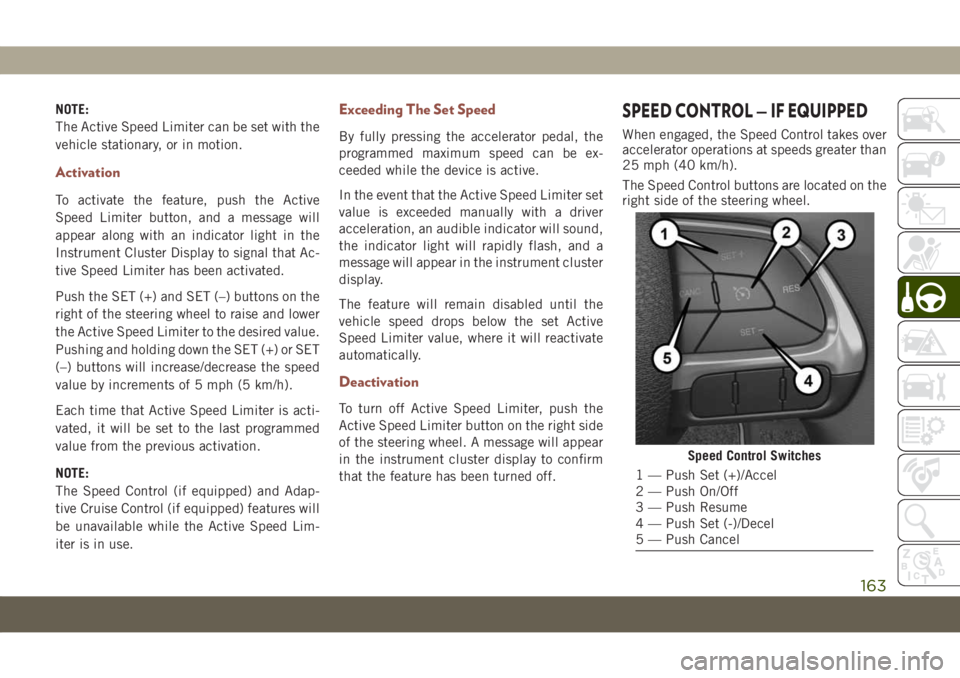
The Speed Control buttons are located on the
right side of the steering wheel.
Speed Control Switches
1 — Push Set (+)/Accel
2 — Push On/Off
3 — Push Resume
4 — Push Set (-)/Decel
5 — Push Cancel
163