turn signal JEEP COMPASS 2019 Owner handbook (in English)
[x] Cancel search | Manufacturer: JEEP, Model Year: 2019, Model line: COMPASS, Model: JEEP COMPASS 2019Pages: 362, PDF Size: 6.23 MB
Page 8 of 362
WELCOME FROM FCA
HOW TO FIND YOUR OWNER’S MANUAL ONLINE.... 1
HOW TO USE THIS MANUAL
HOW TO USE THIS MANUAL............... 2Essential Information................ 2
Symbols........................ 2
ROLLOVER WARNING................... 2
IMPORTANT NOTICE................... 3
WARNINGS AND CAUTIONS............... 4
VEHICLE CHANGES/ALTERATIONS............ 4
GRAPHICAL TABLE OF CONTENTS
INSTRUMENT PANEL.................. 11
INTERIOR......................... 12
GETTING TO KNOW YOUR VEHICLE
KEYS........................... 13Key Fobs...................... 13
IGNITION SWITCH.................... 15Keyless Enter-N-Go — Ignition —
If Equipped..................... 15
Integrated/Manual Ignition — If Equipped . . 16
Electronic Steering Wheel Lock —
If Equipped..................... 16
Mechanical Steering Wheel Lock —
If Equipped..................... 16
REMOTE STARTING SYSTEM — IF EQUIPPED.... 17How To Use Remote Start — If Equipped . . . 17
To Enter Remote Start Mode........... 18
VEHICLE SECURITY ALARM — IF EQUIPPED..... 18To Arm The System................ 18
To Disarm The System.............. 19
Security System Manual Override........ 19
PREMIUM VEHICLE SECURITY ALARM —
IF EQUIPPED...................... 19
To Arm The System................ 20
To Disarm The System.............. 20
Security System Manual Override........ 21
DOORS.......................... 21Keyless Enter-N-Go — Passive Entry...... 21
Child-Protection Door Lock System —
Rear Doors..................... 23
SEATS .......................... 24Manual Adjustment (Rear Seats)........ 24
Driver Memory Seat — If Equipped....... 26
Front Heated Seats — If Equipped....... 28
Front Ventilated Seats — If Equipped..... 29
40/20/40 Rear Seat Armrest— If Equipped . 29
HEAD RESTRAINTS................... 29Front Head Restraint Adjustment........ 30
Rear Head Restraints............... 31
STEERING WHEEL................... 32Tilt/Telescoping Steering Column........ 32
Heated Steering Wheel — If Equipped..... 32
EXTERIOR LIGHTS.................... 33Multifunction Lever................ 33
Headlight Switch.................. 33
Daytime Running Lights (DRL) —
If Equipped..................... 34
High/Low Beam Switch.............. 34
Automatic High Beam Headlamp Control —
If Equipped..................... 34
Flash-To-Pass................... 34
Automatic Headlights — If Equipped..... 34
Headlight Time Delay............... 35
Lights-On Reminder — If Equipped...... 35
Front And Rear Fog Lights — If Equipped . . . 35
Turn Signals.................... 36Headlight Leveling System — If Equipped . . 36
Battery Saver Feature............... 36
WINDSHIELD WIPERS AND WASHERS......... 37Windshield Wiper Operation........... 37
Rain Sensing Wipers — If Equipped...... 38
Rear Window Wiper/Washer........... 39
CLIMATE CONTROLS................... 39Automatic Climate Controls Overview..... 39
Automatic Temperature Control (ATC)..... 47
Operating Tips................... 47
WINDOWS........................ 48Power Window Controls.............. 48
Auto-Down Feature................ 49
Auto-Up Feature With Anti-Pinch Protection . 49
Window Lockout Switch............. 49
Wind Buffeting.................. 50
POWER SUNROOF WITH POWER SHADE —
IF EQUIPPED....................... 50
Opening Sunroof.................. 51
Opening Sunroof — Vent............. 51
Closing Sunroof.................. 51
Opening Power Shade............... 51
Closing Power Shade............... 52
Pinch Protect Feature............... 52
Sunroof Maintenance............... 52
Ignition Off Operation............... 53
HOOD.......................... 53Opening The Hood................. 53
Closing The Hood................. 53
LIFTGATE......................... 54Opening....................... 54
Closing........................ 54
Power Liftgate — If Equipped.......... 54
INTERNAL EQUIPMENT................. 56Power Outlets.................... 56
TABLE OF CONTENTS
6
Page 19 of 362
REMOTE STARTING
SYSTEM — IF EQUIPPED
• Push the remote start button
on the key fob twice within five
seconds. Pushing the remote
start button a third time shuts
the engine off.
• To drive the vehicle, push the START/STOP
button to turn the ignition to the ON/RUN
mode.
• With remote start, the engine will only run
for 15 minutes (timeout) unless the igni-
tion is placed in the ON/RUN mode.
• The vehicle must be started with the key
after two consecutive timeouts.
WARNING!
• Do not start or run an engine in a closed
garage or confined area. Exhaust gas
contains Carbon Monoxide (CO) which is
odorless and colorless. Carbon Monox-
ide is poisonous and can cause serious
injury or death when inhaled.
WARNING!
• Keep key fobs away from children. Op-
eration of the Remote Start System, win-
dows, door locks or other controls could
cause serious injury or death.
How To Use Remote Start — If Equipped
Push remote start button on the key fob twice
within five seconds. Pushing the remote start
button a third time shuts the engine off.
To drive the vehicle, push unlock button,
insert the key in the ignition and turn to the
ON/RUN position.
NOTE:
• With remote start, the engine will only run
for 15 minutes (timeout) unless the igni-
tion key is placed in the ON/RUN position.
• The vehicle must be started with the key
after two consecutive timeouts.
All of the following conditions must be met
before the engine will remote start:
• Gear selector in PARK
• Doors closed• Hood closed
• Liftgate closed
• Hazard switch off
• Brake switch inactive (brake pedal not
pushed)
• Battery at an acceptable charge level
• Check engine light shall not be present
• System not disabled from previous remote
start event
• Vehicle alarm system indicator flashing
• Ignition in STOP/OFF position
• Fuel level meets minimum requirement
• Vehicle security alarm is not signaling an
intrusion
WARNING!
• Do not start or run an engine in a closed
garage or confined area. Exhaust gas
contains Carbon Monoxide (CO) which is
odorless and colorless. Carbon Monox-
ide is poisonous and can cause serious
injury or death when inhaled.
17
Page 20 of 362
WARNING!
• Keep key fobs away from children. Op-
eration of the Remote Start System, win-
dows, door locks or other controls could
cause serious injury or death.
To Enter Remote Start Mode
Push and release the remote start button on
the key fob twice within five seconds. The
vehicle doors will lock, the parking lights will
flash, and the horn will chirp twice (if pro-
grammed). Then, the engine will start, and
the vehicle will remain in the Remote Start
mode for a 15-minute cycle.
NOTE:
• If an engine fault is present or fuel level is
low, the vehicle will start and then shut
down in 10 seconds.
• The park lamps will turn on and remain on
during Remote Start mode.
• For security, power window and power sun-
roof operation (if equipped) are disabled
when the vehicle is in the Remote Start
mode.• The engine can be started two consecutive
times with the key fob. However, the igni-
tion must be cycled by pushing the START/
STOP button twice (or the ignition switch
must be cycled to the ON/RUN position)
before you can repeat the start sequence
for a third cycle.
VEHICLE SECURITY ALARM
— IF EQUIPPED
The vehicle security alarm monitors the ve-
hicle doors, hood, liftgate, and the Keyless
Enter-N-Go — Ignition for unauthorized op-
eration. While the vehicle security alarm is
armed, interior switches for door locks and
liftgate release are disabled. If something
triggers the alarm, the vehicle security alarm
will provide the following audible and visible
signals:
• The horn will pulse
• The turn signals will flash
• The vehicle security light in the instrument
cluster will flash
To Arm The System
Follow these steps to arm the vehicle security
alarm:
1. Make sure the vehicle’s ignition is placed
in the “OFF” mode.
• For vehicles equipped with Keyless En-
try, make sure the vehicle’s keyless
ignition system is OFF.
2. Perform one of the following methods to
lock the vehicle:
• Push the lock button on the interior
power door lock switch with the driver
and/or passenger door open.
• Push the lock button on the exterior
Passive Entry Door Handle with a valid
key fob available in the same exterior
zone, refer to "Doors" in "Getting To
Know Your Vehicle" in the Owner’s
Manual at for further information.
•
Push the lock button on the exterior Pas-
sive Entry Door Handle with a valid key
fob available in the same exterior zone.
• Push the lock button on the key fob.
3. If any doors are open, close them.
GETTING TO KNOW YOUR VEHICLE
18
Page 35 of 362
Vehicles Equipped With Remote Start
On models that are equipped with remote
start, the heated steering wheel can be pro-
grammed to come on during a remote start.
This feature can be programmed through the
Uconnect system. Refer to “Uconnect Set-
tings” in “Multimedia” in the Owner’s
Manual for further information.
WARNING!
• Persons who are unable to feel pain to
the skin because of advanced age,
chronic illness, diabetes, spinal cord in-
jury, medication, alcohol use, exhaus-
tion, or other physical conditions must
exercise care when using the steering
wheel heater. It may cause burns even at
low temperatures, especially if used for
long periods.
• Do not place anything on the steering
wheel that insulates against heat, such
as a blanket or steering wheel covers of
any type and material. This may cause
the steering wheel heater to overheat.
EXTERIOR LIGHTS
Multifunction Lever
The multifunction lever controls the opera-
tion of the turn signals, headlight beam se-
lection and passing lights. The multifunction
lever is located on the left side of the steering
column.
Headlight Switch
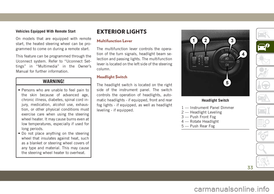
The headlight switch is located on the right
side of the instrument panel. The switch
controls the operation of headlights, auto-
matic headlights - if equipped, front and rear
fog lights - if equipped, as well as headlight
leveling - if equipped.
Headlight Switch
1 — Instrument Panel Dimmer
2 — Headlight Leveling
3 — Push Front Fog
4 — Rotate Headlight
5 — Push Rear Fog
33
Page 36 of 362
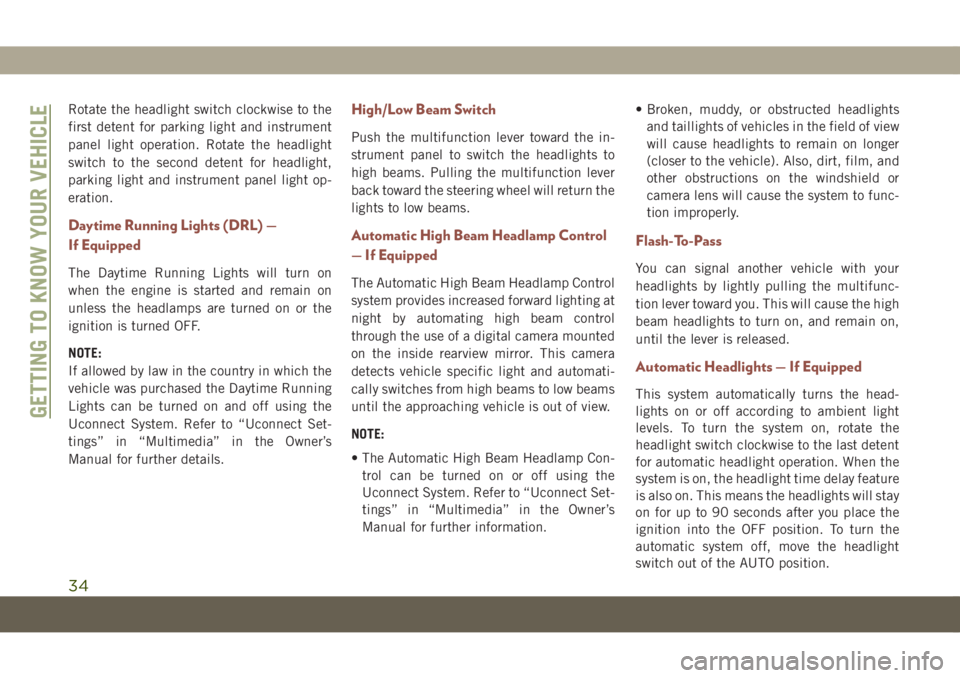
Rotate the headlight switch clockwise to the
first detent for parking light and instrument
panel light operation. Rotate the headlight
switch to the second detent for headlight,
parking light and instrument panel light op-
eration.
Daytime Running Lights (DRL) —
If Equipped
The Daytime Running Lights will turn on
when the engine is started and remain on
unless the headlamps are turned on or the
ignition is turned OFF.
NOTE:
If allowed by law in the country in which the
vehicle was purchased the Daytime Running
Lights can be turned on and off using the
Uconnect System. Refer to “Uconnect Set-
tings” in “Multimedia” in the Owner’s
Manual for further details.
High/Low Beam Switch
Push the multifunction lever toward the in-
strument panel to switch the headlights to
high beams. Pulling the multifunction lever
back toward the steering wheel will return the
lights to low beams.
Automatic High Beam Headlamp Control
— If Equipped
The Automatic High Beam Headlamp Control
system provides increased forward lighting at
night by automating high beam control
through the use of a digital camera mounted
on the inside rearview mirror. This camera
detects vehicle specific light and automati-
cally switches from high beams to low beams
until the approaching vehicle is out of view.
NOTE:
• The Automatic High Beam Headlamp Con-
trol can be turned on or off using the
Uconnect System. Refer to “Uconnect Set-
tings” in “Multimedia” in the Owner’s
Manual for further information.• Broken, muddy, or obstructed headlights
and taillights of vehicles in the field of view
will cause headlights to remain on longer
(closer to the vehicle). Also, dirt, film, and
other obstructions on the windshield or
camera lens will cause the system to func-
tion improperly.
Flash-To-Pass
You can signal another vehicle with your
headlights by lightly pulling the multifunc-
tion lever toward you. This will cause the high
beam headlights to turn on, and remain on,
until the lever is released.
Automatic Headlights — If Equipped
This system automatically turns the head-
lights on or off according to ambient light
levels. To turn the system on, rotate the
headlight switch clockwise to the last detent
for automatic headlight operation. When the
system is on, the headlight time delay feature
is also on. This means the headlights will stay
on for up to 90 seconds after you place the
ignition into the OFF position. To turn the
automatic system off, move the headlight
switch out of the AUTO position.
GETTING TO KNOW YOUR VEHICLE
34
Page 38 of 362
An indicator light in the instrument cluster
illuminates when the fog lights are turned on.
Turn Signals
Move the multifunction lever up or down and
the arrows on each side of the instrument
cluster display flash to show proper operation
of the front and rear turn signal lights.
NOTE:
• If either light remains on and does not
flash, or there is a very fast flash rate, check
for a defective outside light bulb. If an
indicator fails to light when the lever is
moved, it would suggest that the indicator
bulb is defective.
• A “Turn Signal On” message will appear in
the instrument cluster display and a con-
tinuous chime will sound if the vehicle is
driven more than 1 mile (1.6 km) with
either turn signal on.
•
When the Daytime Running Lights are on and
a turn signal is activated, the Daytime Run-
ning Lamp will turn off on the side of the
vehicle in which the turn signal is flashing.
The Daytime Running Lamp will turn back on
when the turn signal is turned off.
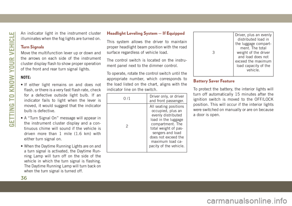
Headlight Leveling System — If Equipped
This system allows the driver to maintain
proper headlight beam position with the road
surface regardless of vehicle load.
The control switch is located on the instru-
ment panel next to the dimmer control.
To operate, rotate the control switch until the
appropriate number, which corresponds to
the load listed on the chart, aligns with the
indicator line on the switch.
0/1Driver only, or driver
and front passenger.
2All seating positions
occupied, plus an
evenly distributed
load in the luggage
compartment. The
total weight of pas-
sengers and load
does not exceed the
maximum load ca-
pacity of the vehicle.
3Driver, plus an evenly
distributed load in
the luggage compart-
ment. The total
weight of the driver
and load does not
exceed the maximum
load capacity of the
vehicle.
Battery Saver Feature
To protect the battery, the interior lights will
turn off automatically 15 minutes after the
ignition switch is moved to the OFF/LOCK
position. This will occur if the interior lights
were switched on manually or are on because
a door is open.
GETTING TO KNOW YOUR VEHICLE
36
Page 57 of 362
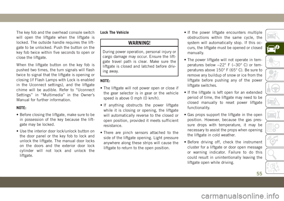
The key fob and the overhead console switch
will open the liftgate when the liftgate is
locked. The outside handle requires the lift-
gate to be unlocked. Push the button on the
key fob twice within five seconds to open or
close the liftgate.
When the liftgate button on the key fob is
pushed two times, the turn signals will flash
twice to signal that the liftgate is opening or
closing (if Flash Lamps with Lock is enabled
in the Uconnect settings), and the liftgate
chime will be audible. Refer to “Uconnect
Settings” in “Multimedia” in the Owner’s
Manual for further information.
NOTE:
• Before closing the liftgate, make sure to be
in possession of the key because the lift-
gate may be locked.
• Use the interior door lock/unlock button on
the door panel or the key fob to lock and
unlock the liftgate. The manual door locks
on the doors and the exterior door lock
cylinder will not lock and unlock the
liftgate.Lock The Vehicle
WARNING!
During power operation, personal injury or
cargo damage may occur. Ensure the lift-
gate travel path is clear. Make sure the
liftgate is closed and latched before driv-
ing away.
NOTE:
• The liftgate will not power open or close if
the gear selector is in gear or the vehicle
speed is above 0 mph (0 km/h).
• If anything obstructs the power liftgate
while it is closing or opening, the liftgate
will automatically reverse to the closed or
open position, provided it meets sufficient
resistance.
• There are pinch sensors attached to the
side of the liftgate opening. Light pressure
anywhere along these strips will cause the
liftgate to return to the open position.• If the power liftgate encounters multiple
obstructions within the same cycle, the
system will automatically stop. If this oc-
curs, the liftgate must be opened or closed
manually.
• The power liftgate will not operate in tem-
peratures below −22° F (−30° C) or tem-
peratures above 150° F (65° C). Be sure to
remove any buildup of snow or ice from the
liftgate before pushing any of the power
liftgate switches.
• If the liftgate is left open for an extended
period of time, the liftgate may need to be
closed manually to reset power liftgate
functionality.
• Gas props support the liftgate in the open
position. However, because the gas pres-
sure drops with temperature, it may be
necessary to assist the props when opening
the liftgate in cold weather.
• Before driving off, check the instrument
cluster for a liftgate or door open message
or warning indicator. Failure to do this
could result in unintentionally leaving the
liftgate open while driving.
55
Page 66 of 362
MESSAGE DESCRIPTION
Engine Will Not Start Service
AdBlue System See DealerNOTE:
• The display may take up to five seconds to update after adding 2 gallons (7.5 Liters) or more of AdBlue
(UREA) to the AdBlue (UREA) tank. If you have a fault related to the AdBlue (UREA) system, the display
may not update to the new level. See an authorized dealer for service.
• AdBlue freezes at temperatures lower than 12°F (-11°C). If the car stands for a long time at this
temperature, refilling could be difficult. For this reason, it is advised to park the vehicle in a garage
and/or heated environment, and wait for the AdBlue (UREA) to return to liquid state before topping up.
TRIP COMPUTER
Push and release the up or down arrow button
until the Trip A or Trip B icon is highlighted in
the instrument cluster display (Toggle left or
right to select Trip A or Trip B). Push and
release the OK button to display the Trip
information.
WARNING LIGHTS
AND MESSAGES
The warning/indicator lights will illuminate in
the instrument panel together with a dedi-
cated message and/or acoustic signal when
applicable. These indications are indicative
and precautionary and as such must not be
considered as exhaustive and/or alternative
to the information contained in the Owner’s
Manual, which you are advised to read care-
fully in all cases. Always refer to the informa-
tion in this chapter in the event of a failure
indication. All active telltales will display first
if applicable. The system check menu may
appear different based upon equipment op-
tions and current vehicle status. Some tell-
tales are optional and may not appear.
Red Warning Lights
— Air Bag Warning Light
This warning light will illuminate to indicate
a fault with the air bag, and will turn on for
four to eight seconds as a bulb check when
the ignition is placed in the ON/RUN or
ACC/ON/RUN position. This light will illumi-
nate with a single chime when a fault with the
air bag has been detected, it will stay on until
the fault is cleared. If the light is either not on
during startup, stays on, or turns on while
driving, have the system inspected at an
authorized dealer as soon as possible.
GETTING TO KNOW YOUR INSTRUMENT PANEL
64
Page 72 of 362
WARNING!
This could result in death or serious injury
to the driver, occupants or others.
CAUTION!
Prolonged driving with the Malfunction
Indicator Light (MIL) on could cause dam-
age to the vehicle control system. It also
could affect fuel economy and driveability.
If the MIL is flashing, severe catalytic
converter damage and power loss will soon
occur. Immediate service is required.
— AdBlue (UREA) Injection System
Failure Warning Light — If Equipped
This warning light will illuminate along with a
dedicated message on the display (If
Equipped) if an unknown fluid not conform-
ing with acceptable characteristics is in-
serted, or if an average consumption of Ad-
Blue (UREA) over 50% is detected. Contact
an authorized dealer as soon as possible.If the problem is not solved, a specific mes-
sage will appear on the Instrument Cluster
Display whenever a certain threshold is
reached until it will no longer be possible to
start the engine.
When about 125 mi (200 km) are remaining
before the AdBlue (UREA) tank is empty, a
continuous dedicated message will appear on
the instrument panel, accompanied by a
buzzer sound (If Equipped).
— Service Adaptive Cruise Control
Warning Light — If Equipped
This light will turn on when a ACC is not
operating and needs service. Refer to “Adap-
tive Cruise Control (ACC)” in “Starting And
Operating” for further information.
SERV4WD— Service 4WD Warning Light —
If Equipped
This warning light will illuminate to signal a
fault with the 4WD system. If the light stays
on or comes on during driving, it means that
the 4WD system is not functioning properly
and that service is required. We recommend
you drive to the nearest service center and
have the vehicle serviced immediately.
— Service Forward Collision Warning
(FCW) Light — If Equipped
This warning light will illuminate to indicate
a fault in the Forward Collision Warning Sys-
tem. Contact an authorized dealer for service.
Refer to "Forward Collision Warning (FCW)" in
"Safety" for further information.
— Service Stop/Start System Warning
Light — If Equipped
This warning light will illuminate when the
Stop/Start system is not functioning properly
and service is required. Contact an autho-
rized dealer for service.
— Tire Pressure Monitoring System
(TPMS) Warning Light
The warning light switches on and a message
is displayed to indicate that the tire pressure
is lower than the recommended value and/or
that slow pressure loss is occurring. In these
cases, optimal tire duration and fuel con-
sumption may not be guaranteed.
Should one or more tires be in the condition
mentioned above, the display will show the
indications corresponding to each tire.
GETTING TO KNOW YOUR INSTRUMENT PANEL
70
Page 74 of 362
— Towing Hook Breakdown Warning
Light — If Equipped
This light illuminates when there is a failure
with the tow hook. Contact an authorized
dealer for service.
Yellow Indicator Lights
— 4WD Low Indicator Light —
If Equipped
This light alerts the driver that the vehicle is
in the four-wheel drive LOW mode. The front
and rear driveshafts are mechanically locked
together forcing the front and rear wheels to
rotate at the same speed. Low range provides
a greater gear reduction ratio to provide in-
creased torque at the wheels.
Refer to “Four-Wheel Drive Operation — If
Equipped” in “Starting And Operating” for
further information on four-wheel drive op-
eration and proper use.
— 4WD Lock Indicator Light
This light alerts the driver that the vehicle is
in the four-wheel drive LOCK mode. The front
and rear driveshafts are mechanically locked
together, forcing the front and rear wheels to
rotate at the same speed.
Refer to “Four-Wheel Drive Operation” in
“Starting And Operating” for further informa-
tion on four-wheel drive operation and proper
use.
— Active Speed Limiter Fault
Indicator Light — If Equipped
This warning light will illuminate to signal
when there is a fault detected with the Active
Speed Limiter.
— Diesel Particulate Filter (DPF)
Cleaning In Progress Indicator Light —
Diesel Versions With DPF Only (If Equipped)
This indicator light will illuminate, or a mes-
sage will appear, to indicate that the DPF
system needs to eliminate the trapped pollut-
ants (particulate) through the regeneration
process.The light/message does not switch on during
every DPF regeneration, but only when driv-
ing conditions require that the driver is noti-
fied. To turn off the symbol, keep the vehicle
in motion until the regeneration process is
over. On average, the process lasts 15 min-
utes.
Optimal conditions for completing the pro-
cess are achieved by travelling at 37 mph
(60 km/h) with engine speed above
2000 rpm.
When this light/message switches on, it does
not indicate a vehicle failure and thus it
should not be taken to a workshop.
NOTE:
On some versions, together with the symbol
switching on, the display shows a dedicated
message.CAUTION!
Vehicle travel speed should always be
adapted to the traffic and weather condi-
tions, and must always comply with traffic
regulations.
GETTING TO KNOW YOUR INSTRUMENT PANEL
72