display JEEP COMPASS 2019 Owner handbook (in English)
[x] Cancel search | Manufacturer: JEEP, Model Year: 2019, Model line: COMPASS, Model: JEEP COMPASS 2019Pages: 362, PDF Size: 6.23 MB
Page 93 of 362
Modes Of Operation
Three selectable modes of operation are
available in the Uconnect System. Refer to
“Uconnect Settings” in “Multimedia” in the
Owner’s Manual for further information.
Blind Spot Alert Lights Only (Default Setting)
When operating in Blind Spot Alert mode, the
BSM system will provide a visual alert in the
appropriate side view mirror based on a de-
tected object. However, when the system is
operating in Rear Cross Path (RCP) mode, the
system will respond with both visual and
audible alerts when a detected object is pres-
ent. Whenever an audible alert is requested,
the radio is muted.
Blind Spot Alert Lights/Chime
When operating in Blind Spot Alert Lights/
Chime mode, the BSM system will provide a
visual alert in the appropriate side view mirror
based on a detected object. If the turn signal
is then activated, and it corresponds to an
alert present on that side of the vehicle, an
audible chime will also be sounded. When-
ever a turn signal and detected object are
present on the same side at the same time,both the visual and audible alerts will be
issued. In addition to the audible alert the
radio (if on) will also be muted.
NOTE:
Whenever an audible alert is requested by the
BSM system, the radio is also muted.
When the system is in RCP, the system shall
respond with both visual and audible alerts
when a detected object is present. Whenever
an audible alert is requested, the radio vol-
ume is reduced. Turn/hazard signal status is
ignored; the RCP state always requests the
chime.
Blind Spot Alert Off
When the BSM system is turned off there will
be no visual or audible alerts from either the
BSM or RCP systems.
NOTE:
The BSM system will store the current oper-
ating mode when the vehicle is shut off. Each
time the vehicle is started the previously
stored mode will be recalled and used.Blocked Sensor
If the system detects degraded performance
due to contamination or foreign objects, a
message will warn you of a blocked sensor
and the warning indicators in side view mir-
rors will be illuminated. The warning indica-
tors will remain illuminated until blockage
clearing conditions are met. First clear the
fascia area around the sensors of the block-
age. After removing the blockage, reset the
system by cycling the ignition from ON to OFF
and then back ON.
Forward Collision Warning (FCW)
With Mitigation — If Equipped
Forward Collision Warning (FCW)
With Mitigation Operation
The Forward Collision Warning (FCW) system
with mitigation provides the driver with au-
dible warnings, visual warnings (within the
instrument cluster display), and may apply a
brake jerk to warn the driver when it detects a
potential frontal collision. The warnings and
limited braking are intended to provide the
driver with enough time to react, avoid or
mitigate the potential collision.
91
Page 95 of 362
Changing the FCW status to “Warning Only”
prevents the system from providing autono-
mous braking, or additional brake support if
the driver is not braking adequately in the
event of a potential frontal collision.
Changing the FCW status to off deactivates
the system, so no warning or autonomous
braking will be available in case of a possible
collision
NOTE:
The FCW system state is defaulted to "Full
On" from one ignition cycle to the next. If the
system is turned off, it will reset to "Full On"
when the vehicle is restarted.
Changing FCW Sensitivity And Operating
Status
The FCW Sensitivity And Operation Settings
are programmable through the Uconnect Sys-
tem. Refer to “Uconnect Settings” in “Multi-
media” for further information.
The default status of FCW is the “Medium”
setting and the FCW is in the “Full On”
setting. This allows the system to warn thedriver of a possible collision with the vehicle
in front using audible/visual warnings and it
applies autonomous braking.
Changing the FCW status to “Far” setting
allows the system to warn the driver of a
possible collision with the vehicle in front
using audible/visual warning when the latter
is at a farther distance than "Medium" set-
ting. This provides the most reaction time to
avoid a possible collision.
Changing the FCW status to the “Near” set-
ting, allows the system to warn the driver of a
possible collision with the vehicle in front
when the distance between the vehicle in the
front is much closer. This setting provides
less reaction time than the “Far” and “Me-
dium” settings, which allows for a more dy-
namic driving experience.
NOTE:
• The system will NOT retain the last setting
selected by the driver after ignition shut
down. The system will reset to Medium
sensitivity with FCW "Full On" setting when
the vehicle is restarted.• FCW may not react to irrelevant objects
such as overhead objects, ground reflec-
tions, objects not in the path of the vehicle,
stationary objects that are far away, oncom-
ing traffic, or leading vehicles with the
same or higher rate of speed.
• If FCW is disabled, unavailable screens will
be displayed.
FCW Limited Warning
If the instrument cluster display reads “ACC/
FCW Limited Functionality” or “ACC/FCW
Limited Functionality Clean Front Wind-
shield” momentarily, there may be a condi-
tion that limits FCW functionality. Although
the vehicle is still drivable under normal
conditions, the active braking may not be
fully available. Once the condition that lim-
ited the system performance is no longer
present, the system will return to its full
performance state. If the problem persists,
see your authorized dealer.
Service FCW Warning
If the system turns off, and the instrument
cluster display reads “FCW Unavailable Ser-
vice Required”, this indicates there is an
93
Page 97 of 362
CAUTION!
your vehicle. Undesirable system opera-
tion or sensor damage may result when
using replacement equipment that is not
of the same size, type, and/or style. The
TPM sensor is not designed for use on
aftermarket wheels and may contribute
to a poor overall system performance or
sensor damage. Customers are encour-
aged to use OEM wheels to assure
proper TPM feature operation.
• Using aftermarket tire sealants may
cause the Tire Pressure Monitoring Sys-
tem (TPMS) sensor to become inoper-
able. After using an aftermarket tire
sealant it is recommended that you take
your vehicle to your authorized dealer to
have your sensor function checked.
• After inspecting or adjusting the tire
pressure always reinstall the valve stem
cap. This will prevent moisture and dirt
from entering the valve stem, which
could damage the TPMS sensor.NOTE:
• The TPMS is not intended to replace nor-
mal tire care and maintenance, or to pro-
vide warning of a tire failure or condition.
• The TPMS should not be used as a tire
pressure gauge while adjusting your tire
pressure.
• Driving on a significantly underinflated tire
causes the tire to overheat and can lead to
tire failure. Underinflation also reduces
fuel efficiency and tire tread life, and may
affect the vehicle’s handling and stopping
ability.
• The TPMS is not a substitute for proper tire
maintenance, and it is the driver’s respon-
sibility to maintain correct tire pressure
using an accurate tire pressure gauge, even
if underinflation has not reached the level
to trigger illumination of the TPMS Warning
Light.
• Seasonal temperature changes will affect
tire pressure, and the TPMS will monitor
the actual tire pressure in the tire.
• The system only warns the tire pressure is
low: it is not able to inflate them.
Premium System
The Tire Pressure Monitor System (TPMS)
uses wireless technology with wheel rim
mounted electronic sensors to monitor tire
pressure levels. Sensors, mounted to each
wheel as part of the valve stem, transmit tire
pressure readings to the receiver module.
NOTE:
It is particularly important for you to check
the tire pressure in all of the tires on your
vehicle monthly and to maintain the proper
pressure.
The TPMS consists of the following compo-
nents:
• Receiver Module
• Four Tire Pressure Monitoring Sensors
• Various Tire Pressure Monitoring System
messages, which will display in the instru-
ment cluster display.
• Tire Pressure Monitoring System Warning
Light
95
Page 98 of 362
Tire Pressure Monitoring Low Pressure
Warnings
The Tire Pressure Monitoring System
Warning Light will illuminate in the
instrument cluster and a chime will
sound when tire pressure is low in one or
more of the four active road tires. In addition,
the instrument cluster will display a "Tire
Low" message and a graphic showing the
pressure values of each tire with the low tire
pressure values highlighted or in a different
color.
Should this occur, you should stop as soon as
possible and inflate the tires with low pres-
sure (those highlighted or in a different color
in the instrument cluster display graphic) to
the vehicle’s recommended cold placard
pressure value. Once the system receives the
updated tire pressures, the system will auto-
matically update, the pressure values in the
graphic display in the instrument cluster will
stop being highlighted or return to their origi-
nal color, and the Tire Pressure Monitoring
System Warning Light will turn off.NOTE:
When filling warm tires, the tire pressure may
need to be increased up to an additional 4 psi
(28 kPa) above the recommended cold plac-
ard pressure in order to turn the Tire Pressure
Monitoring System Warning Light off. The
vehicle may need to be driven for up to
10 minutes above 15 mph (24 km/h) in order
for the TPMS to receive this information.
Service TPMS Warning
When a system fault is detected, the Tire
Pressure Monitoring System Warning Light
will flash on and off for 75 seconds and then
remain on solid. The system fault will also
sound a chime. In addition, the instrument
cluster will display a "SERVICE TPM SYS-
TEM" message for a minimum of five seconds
and then display dashes (- -) in place of the
pressure value to indicate which sensor is not
being received.
If the ignition key is cycled, this sequence
will repeat, providing the system fault still
exists. If the system fault no longer exists, the
Tire Pressure Monitoring System Warning
Light will no longer flash, and the “SERVICE
TPM SYSTEM” message will no longer dis-play, and a pressure value will display in
place of the dashes. A system fault can occur
due to any of the following:
• Jamming due to electronic devices or driv-
ing next to facilities emitting the same
radio frequencies as the TPMS sensors.
• Installing some form of aftermarket window
tinting that affects radio wave signals.
• Lots of snow or ice around the wheels or
wheel housings.
• Using tire chains on the vehicle.
• Using wheels/tires not equipped with
TPMS sensors.
Vehicles With Compact Spare or Non-Matching
Full Size Spare
1. The compact spare tire or non-matching
full size does not have a tire pressure
monitoring sensor. Therefore, the TPMS
will not monitor the pressure in the com-
pact or non-matching full size spare tire.
2. If you install the compact or non-
matching full size spare tire in place of a
road tire that has a pressure below the
low-pressure warning limit, upon the next
ignition key cycle, the Tire Pressure Moni-
SAFETY
96
Page 99 of 362
toring System Warning Light will remain
on and a chime will sound. In addition,
the graphic in the instrument cluster will
still display a different color or high-
lighted pressure value.
3. After driving the vehicle for up to 10 min-
utes above 15 mph (24 km/h), the Tire
Pressure Monitoring System Warning
Light will flash on and off for 75 seconds
and then remain on solid. In addition, the
instrument cluster will display a “SER-
VICE TPM SYSTEM” message for five sec-
onds and then display dashes (- -) in place
of the pressure value.
4. For each subsequent ignition key cycle, a
chime will sound, the Tire Pressure Moni-
toring System Warning Light will flash on
and off for 75 seconds and then remain on
solid, and the instrument cluster will dis-
play a “SERVICE TPM SYSTEM” message
for five seconds and then display dashes (-
-) in place of the pressure value.
5. Once you repair or replace the original
road tire and reinstall it on the vehicle in
place of the compact spare, the TPMS will
update automatically. In addition, the TirePressure Monitoring System Warning
Light will turn off and the graphic in the
instrument cluster will display a new pres-
sure value instead of dashes (- -), as long
as no tire pressure is below the low-
pressure warning limit in any of the four
active road tires. The vehicle may need to
be driven for up to 10 minutes above
15 mph (24 km/h) in order for the TPMS
to receive this information.
TPMS Deactivation — If Equipped
The TPMS can be deactivated if replacing all
four wheel and tire assemblies (road tires)
with wheel and tire assemblies that do not
have TPMS Sensors, such as when installing
winter wheel and tire assemblies on your
vehicle.
To deactivate the TPMS, first replace all four
wheel and tire assemblies (road tires) with
tires not equipped with Tire Pressure Moni-
toring (TPM) Sensors. Then, drive the vehicle
for 10 minutes above 15 mph (24 km/h). The
TPMS will chime, the Tire Pressure Monitor-
ing System Warning Light will flash on and off
for 75 seconds and then remain on. Theinstrument cluster will display the “SERVICE
TPM SYSTEM” message and then display
dashes (--) in place of the pressure values.
Beginning with the next ignition cycle, the
TPMS will no longer chime or display the
“SERVICE TPM SYSTEM” message in the
instrument cluster but dashes (--) will remain
in place of the pressure values.
To reactivate the TPMS, replace all four
wheel and tire assemblies (road tires) with
tires equipped with TPM sensors. Then, drive
the vehicle for up to 10 minutes above
15 mph (24 km/h). The TPMS will chime, the
Tire Pressure Monitoring System Warning
Light will flash on and off for 75 seconds and
then turn off. The instrument cluster will
display the “SERVICE TPM SYSTEM” mes-
sage and then display pressure values in
place of the dashes. On the next ignition
cycle the "SERVICE TPM SYSTEM" message
will no longer be displayed as long as no
system fault exists.
97
Page 112 of 362
Because air bag sensors measure vehicle
deceleration over time, vehicle speed and
damage by themselves are not good indica-
tors of whether or not an air bag should have
deployed.
Seat belts are necessary for your protection in
all collisions, and also are needed to help
keep you in position, away from an inflating
air bag.
When the ORC detects a collision requiring
the front air bags, it signals the inflator units.
A large quantity of non-toxic gas is generated
to inflate the front air bags.
The steering wheel hub trim cover and the
upper passenger side of the instrument panel
separate and fold out of the way as the air
bags inflate to their full size. The front air
bags fully inflate in less time than it takes to
blink your eyes. The front air bags then
quickly deflate while helping to restrain the
driver and front passenger.Passenger Air Bag Disable Feature —
If Equipped
This system allows the driver to DISABLE
(OFF) the Passenger Advanced Front Air Bag
if a child restraintmustbe installed in the
front seat. Only DISABLE (OFF) the Passen-
ger Advanced Front Air Bag if it is absolutely
necessary to install a child restraint in the
front seat. Children 12 years or younger
should ride properly buckled up in a rear
seat, if available. According to crash statis-
tics, children are safer when properly re-
strained in the rear seats rather than in the
front. (Refer to “Child Restraints” in this
section for further information.)
WARNING!
• A DISABLED (OFF) Passenger Advanced
Front Air Bag is deactivated and will not
deploy in a collision.
• A DISABLED (OFF) Passenger Advanced
Front Air Bag will not provide a front
passenger additional protection by
supplementing the seat belts.
WARNING!
• Do not install a child restraint in the
front seat unless the Passenger Air Bag
DISABLE (OFF) Indicator light
on
the center stack is illuminated to show
that the Passenger Advanced Front Air
Bag is DISABLED (OFF).
• In a collision, you and your passengers
can suffer much greater injuries if you
are not properly buckled up. You can
strike the interior of your vehicle or other
passengers, or you can be thrown out of
the vehicle. Always be sure you and
others in your vehicle are buckled up
properly.
The Passenger Advanced Front Air Bag can
be ENABLED (ON) or DISABLED (OFF) by
selecting the desired setting in the instru-
ment cluster display menu. For more infor-
mation on how to access the instrument clus-
ter display, refer to “Instrument Cluster
Display” in “Getting To Know Your Instru-
ment Panel” for further information.SAFETY
110
Page 113 of 362
The Passenger Air Bag DISABLE Feature
consists of the following:
• Occupant Restraint Controller (ORC)
•
Passenger Air Bag DISABLE (OFF)
Indicator Light — an amber light located in
the center stack
•
Passenger Air Bag ENABLE (ON) Indi-
cator Light — an amber light located in the
center stack
•
Air Bag Warning Light — an amber
light located in the instrument cluster
display
The Occupant Restraint Controller (ORC)
monitors the readiness of the electronic parts
of the air bag system whenever the ignition
switch is in the START or ON/RUN position.
The ORC illuminates the Passenger Air Bag
DISABLE (OFF) Indicator Light and the Pas-
senger Air Bag ENABLE (ON) Indicator Light
in the center stack for approximately five to
eight seconds for a self-check when the igni-
tion switch is first in the START or ON/RUN
position. After the self-check, the indicator
light that is illuminated tells the driver and
passenger the status of the Passenger Ad-vanced Front Air Bag. If any of the following
occurs, have an authorized dealer service the
air bag system immediately:
• Both indicator lights do not come on as a
self-check when the ignition is first in the
START or ON/RUN position.
• Both indicator lights stay on after you start
the vehicle.
• Both indicator lights stay off after you start
the vehicle.
• Both indicator lights come on as you drive.
• Both indicator lights turn off as you drive.
Once the self-check is complete, only one
Passenger Air Bag Indicator Light should be
illuminated at a time.
WARNING!
If any of the above conditions occur, indi-
cating there is an issue with the Passenger
Air Bag Indicator Light, the Passenger Ad-
vanced Front Air Bag will remain in the last
selected state (DISABLED or ENABLED).
Passenger Air Bag DISABLE (OFF) Indicator
Light
The Passenger Air Bag DISABLE (OFF) Indi-
cator Light (an amber light located in the
center stack) tells the driver and front pas-
senger when the Passenger Advanced Front
Air Bag is deactivated. The Passenger Air Bag
DISABLE (OFF) Indicator Light on the center
stack will illuminate
to show that the
Passenger Advanced Front Air Bag will not
deploy during a collision.NEVERassume the
Passenger Advanced Front Air Bag is deacti-
vated unless the Passenger Air Bag DISABLE
(OFF) Indicator Light
on the center stack
is illuminated.
Passenger Air Bag ENABLE (ON) Indicator
Light
The Passenger Air Bag ENABLE (ON) Indica-
tor Light (an amber light located in the center
stack) tells the driver and front passenger
when the Passenger Advanced Front Air Bag
is activated. The Passenger Air Bag ENABLE
(ON) Indicator Light on the center stack will
illuminate
to show that the Passenger
Advanced Front Air Bag will deploy during an
impact that requires air bag deployment.
111
Page 114 of 362
NEVERassume the Passenger Advanced Front
Air Bag is activated unless the Passenger Air
Bag ENABLE (ON) Indicator Light
on the
center stack is illuminated.
WARNING!
• NEVER use a rearward facing child re-
straint on a seat protected by an ACTIVE
AIRBAG in front of it, DEATH or SERI-
OUS INJURY to the CHILD can occur.
• It is advisable to always carry children in
a child restraint system on the rear seat,
which is the most protected position in
the event of a collision.
• Should it be necessary to carry a child on
the passenger side front seat in a rear-
facing child restraint system, the pas-
senger side front air bag must be deac-
tivated. Always make sure the airbag
deactivation indicator light is illumi-
nated when using a child restraint sys-
tem. The passenger seat must also be
positioned backward as far as possible
to avoid the child restraint system from
coming into contact with the dashboard.
WARNING!
• A deploying passenger front air bag can
cause death or serious injury to a child
12 years or younger, including a child in
a rear-facing child restraint.
• Children 12 years or younger should
always ride buckled up in the rear seat of
a vehicle with a rear seat.
DISABLING (OFF) the Passenger Advanced Front
Air Bag
To DISABLE (OFF) the Passenger Advanced
Front Air Bag, access the instrument cluster
display main menu located in the instrument
cluster by pushing the Up or Down arrow
button located on the steering wheel, then
complete the following actions:
Action Information
Scroll Up or Down to
“Vehicle Set-Up”
Press the “OK” on
the vehicle steering
wheel to enter
“Vehicle Settings”
Action Information
Scroll Up or Down
using the arrow
buttons on the steer-
ing wheel to select
“Security”
Press the “OK”
button on the steer-
ing wheel to select
“Security”
Press the “OK”
button on the steer-
ing wheel to select
“Passenger AIRBAG”
Scroll Up or Down to
Passenger AIRBAG
OFF “
OFF”NOTE:
If the Passenger
Advanced Front Air
Bag was previously
ENABLED (ON) it
will default to ON
and user will have to
scroll down to select
OFF.
Press the “OK”
button on the steer-
ing wheel to select
Passenger AIRBAG
OFF “
OFF”
SAFETY
112
Page 115 of 362
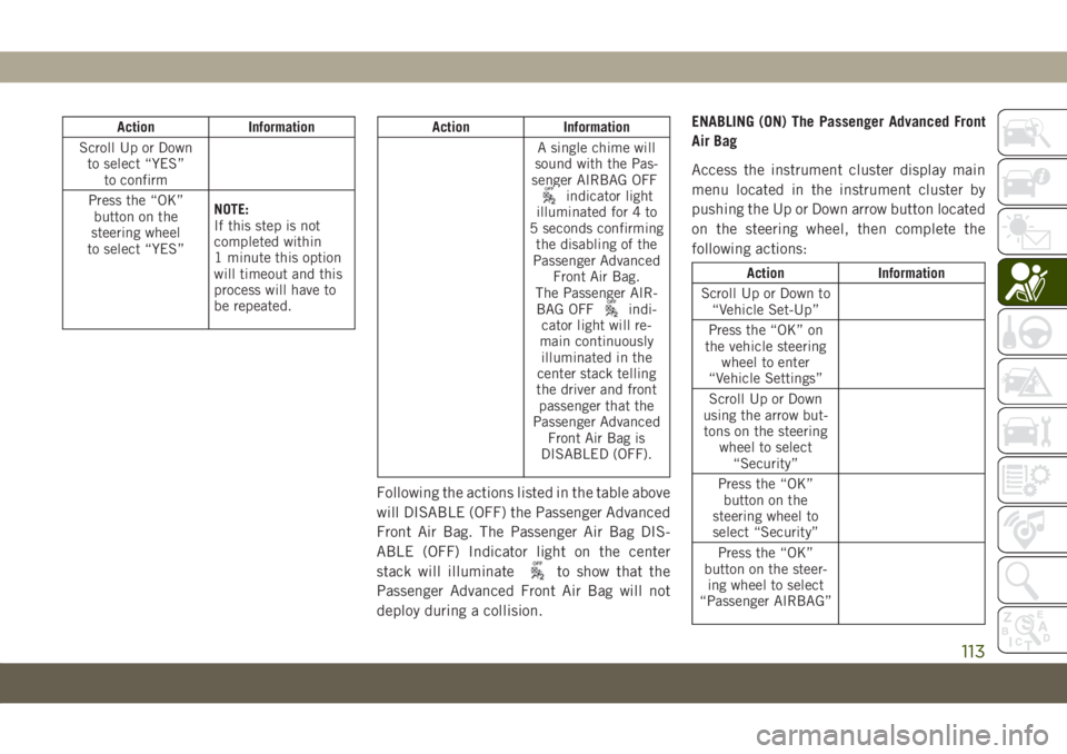
Action Information
Scroll Up or Down
to select “YES”
to confirm
Press the “OK”
button on the
steering wheel
to select “YES”NOTE:
If this step is not
completed within
1 minute this option
will timeout and this
process will have to
be repeated.Action Information
A single chime will
sound with the Pas-
senger AIRBAG OFF
indicator light
illuminated for 4 to
5 seconds confirming
the disabling of the
Passenger Advanced
Front Air Bag.
The Passenger AIR-
BAG OFF
indi-
cator light will re-
main continuously
illuminated in the
center stack telling
the driver and front
passenger that the
Passenger Advanced
Front Air Bag is
DISABLED (OFF).
Following the actions listed in the table above
will DISABLE (OFF) the Passenger Advanced
Front Air Bag. The Passenger Air Bag DIS-
ABLE (OFF) Indicator light on the center
stack will illuminate
to show that the
Passenger Advanced Front Air Bag will not
deploy during a collision.ENABLING (ON) The Passenger Advanced Front
Air Bag
Access the instrument cluster display main
menu located in the instrument cluster by
pushing the Up or Down arrow button located
on the steering wheel, then complete the
following actions:
Action Information
Scroll Up or Down to
“Vehicle Set-Up”
Press the “OK” on
the vehicle steering
wheel to enter
“Vehicle Settings”
Scroll Up or Down
using the arrow but-
tons on the steering
wheel to select
“Security”
Press the “OK”
button on the
steering wheel to
select “Security”
Press the “OK”
button on the steer-
ing wheel to select
“Passenger AIRBAG”
113
Page 122 of 362
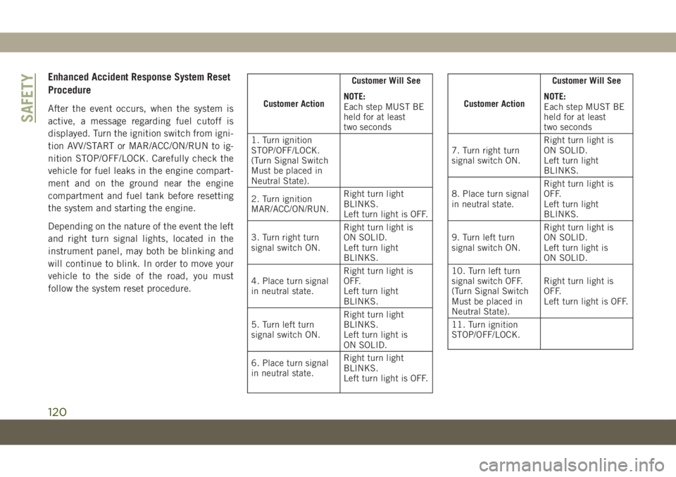
Enhanced Accident Response System Reset
Procedure
After the event occurs, when the system is
active, a message regarding fuel cutoff is
displayed. Turn the ignition switch from igni-
tion AVV/START or MAR/ACC/ON/RUN to ig-
nition STOP/OFF/LOCK. Carefully check the
vehicle for fuel leaks in the engine compart-
ment and on the ground near the engine
compartment and fuel tank before resetting
the system and starting the engine.
Depending on the nature of the event the left
and right turn signal lights, located in the
instrument panel, may both be blinking and
will continue to blink. In order to move your
vehicle to the side of the road, you must
follow the system reset procedure.Customer ActionCustomer Will See
NOTE:
Each step MUST BE
held for at least
two seconds
1. Turn ignition
STOP/OFF/LOCK.
(Turn Signal Switch
Must be placed in
Neutral State).
2. Turn ignition
MAR/ACC/ON/RUN.Right turn light
BLINKS.
Left turn light is OFF.
3. Turn right turn
signal switch ON.Right turn light is
ON SOLID.
Left turn light
BLINKS.
4. Place turn signal
in neutral state.Right turn light is
OFF.
Left turn light
BLINKS.
5. Turn left turn
signal switch ON.Right turn light
BLINKS.
Left turn light is
ON SOLID.
6. Place turn signal
in neutral state.Right turn light
BLINKS.
Left turn light is OFF.Customer ActionCustomer Will See
NOTE:
Each step MUST BE
held for at least
two seconds
7. Turn right turn
signal switch ON.Right turn light is
ON SOLID.
Left turn light
BLINKS.
8. Place turn signal
in neutral state.Right turn light is
OFF.
Left turn light
BLINKS.
9. Turn left turn
signal switch ON.Right turn light is
ON SOLID.
Left turn light is
ON SOLID.
10. Turn left turn
signal switch OFF.
(Turn Signal Switch
Must be placed in
Neutral State).Right turn light is
OFF.
Left turn light is OFF.
11. Turn ignition
STOP/OFF/LOCK.
SAFETY
120