lug pattern JEEP COMPASS 2019 Owner handbook (in English)
[x] Cancel search | Manufacturer: JEEP, Model Year: 2019, Model line: COMPASS, Model: JEEP COMPASS 2019Pages: 362, PDF Size: 6.23 MB
Page 214 of 362

5. Raise the vehicle just enough to remove
the flat tire.
WARNING!
Raising the vehicle higher than necessary
can make the vehicle less stable. It could
slip off the jack and hurt someone near it.
Raise the vehicle only enough to remove
the tire.
6. Remove the wheel bolts and tire.
7. Remove the alignment pin from the jack
assembly and thread the pin into the
wheel hub to assist in mounting the spare
tire.
8. Mount the spare tire.
CAUTION!
Be sure to mount the spare tire with the
valve stem facing outward. The vehicle
could be damaged if the spare tire is
mounted incorrectly.NOTE:
• For vehicles equipped, do not attempt
to install a center cap or wheel cover on
the compact spare.
• Refer to “Compact Spare Tire” and to
“Limited-Use Spare” under “Tires—
General Information” in “Servicing And
Maintenance” in the Owner's Manual
for additional warnings, cautions, and
information about the spare tire, its
use, and operation.
9. Install and lightly tighten the wheel bolts.
WARNING!
To avoid the risk of forcing the vehicle off
the jack, do not tighten the wheel nuts
fully until the vehicle has been lowered.
Failure to follow this warning may result in
serious injury.
10. Lower the vehicle to the ground by turn-
ing the jack handle counterclockwise.11. Finish tightening the wheel bolts. Push
down on the wrench while at the end of
the handle for increased leverage.
Tighten the wheel bolts in a star pattern
until each wheel bolt has been tightened
twice. Refer to “Wheel And Tire Torque
Specifications” in “Technical Specifica-
tions” for the proper lug bolt torque. If in
doubt about the correct tightness, have
them checked with a torque wrench by
an authorized dealer or at a service
station.
12. Place the jack on the foam tray and open
it far enough so that it is secured. Once
placed in position, rotate it clockwise to
lock it in. Replace the alignment pin in
the center hole to lock the jack in place.
WARNING!
A loose tire or jack thrown forward in a
collision or hard stop could endanger the
occupants of the vehicle. Always stow the
jack parts and the spare tire in the places
provided. Have the deflated (flat) tire re-
paired or replaced immediately.
IN CASE OF EMERGENCY
212
Page 215 of 362

Road Tire Installation
1. Mount the road tire on the axle.
2. Install the remaining wheel bolts with the
threaded end of the wheel bolt toward the
wheel. Lightly tighten the wheel bolts.
WARNING!
To avoid the risk of forcing the vehicle off
the jack, do not tighten the wheel bolts
fully until the vehicle has been lowered.
Failure to follow this warning may result in
serious injury.
3. Lower the vehicle to the ground by turning
the jack handle counterclockwise.
4. Finish tightening the wheel bolts. Push
down on the wrench while at the end of
the handle for increased leverage. Tighten
the wheel bolts in a star pattern until each
wheel bolt has been tightened twice. Re-
fer to “Wheel And Tire Torque Specifica-
tions” in “Technical Specifications” for
the proper lug bolt torque. If in doubt
about the correct tightness, have them
checked with a torque wrench by an au-
thorized dealer or service station.5. Lower the jack until it is free. Remove the
wheel blocks. Reassemble the lug wrench
to the jack assembly and stow it in the
spare tire area. Secure the assembly using
the means provided. Release the parking
brake before driving the vehicle.
6. After 25 miles (40 km), check the wheel
bolt torque with a torque wrench to ensure
that all wheel bolts are properly seated
against the wheel.
EC Declaration Of Conformance
1. The undersigned,Jaswant Singh, repre-
senting the Moonlight Tools Pvt. Ltd.,
herewith declares that the machinery de-
scribed below fulfills all the relevant pro-
visions of:
• The EC-directive 2006/42/EC on
Machinery2. Description of machinery.
a.
Generic Denomination:Pantograph jack
b.Function:Lifting Motor Vehicle
Model
CodeModel
NameType Working
load
M6 (556) MPV MLF1 1250Kg
3. Manufacturer Detail
Moonlight Tools Pvt. Ltd.
Vill. Jaspalon, G.T. Road Doraha
Distt. Ludhiana (141421) Punjab (India)
Teh. PH. No. 01628 258302
4. Authorized Person to compile the techni-
cal file
Mr. jaswant Singh DGM (QA & Dev.)
Moonlight Tools Pvt. Ltd.
Ludhiana
5. Reference standard : PF-90065
Date Place Signature Seal
29–03–
2017Doraha
Ludhiana
213
Page 266 of 362

WHEEL AND TIRE TORQUE
SPECIFICATIONS
Proper lug nut/bolt torque is very important to
ensure that the wheel is properly mounted to
the vehicle. Any time a wheel has been re-
moved and reinstalled on the vehicle, the lug
nuts/bolts should be torqued using a properly
calibrated torque wrench using a high quality
six sided (hex) deep wall socket.
Torque Specifications
Lug Nut/Bolt
Torque**Lug Nut/Bolt
SizeLug Nut/Bolt
Socket Size
100 Ft-Lbs
(135 N·m)M12 x 1.25 17 mm
**Use only an authorized dealer recom-
mended lug nuts/bolts and clean or remove
any dirt or oil before tightening.Inspect the wheel mounting surface prior to
mounting the tire and remove any corrosion
or loose particles.
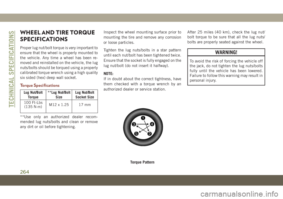
Tighten the lug nuts/bolts in a star pattern
until each nut/bolt has been tightened twice.
Ensure that the socket is fully engaged on the
lug nut/bolt (do not insert it halfway).
NOTE:
If in doubt about the correct tightness, have
them checked with a torque wrench by an
authorized dealer or service station.After 25 miles (40 km), check the lug nut/
bolt torque to be sure that all the lug nuts/
bolts are properly seated against the wheel.
WARNING!
To avoid the risk of forcing the vehicle off
the jack, do not tighten the lug nuts/bolts
fully until the vehicle has been lowered.
Failure to follow this warning may result in
personal injury.
Torque Pattern
TECHNICAL SPECIFICATIONS
264