radio JEEP COMPASS 2019 Owner handbook (in English)
[x] Cancel search | Manufacturer: JEEP, Model Year: 2019, Model line: COMPASS, Model: JEEP COMPASS 2019Pages: 362, PDF Size: 6.23 MB
Page 11 of 362
WHEEL AND TIRE TORQUE SPECIFICATIONS.... 264Torque Specifications.............. 264
DIMENSIONS...................... 265
WHEELS........................ 267
WEIGHTS........................ 268
FUEL REQUIREMENTS — GASOLINE ENGINE.... 269
1.4L Turbo Gasoline Engine.......... 269
Ethanol....................... 269
Materials Added To Fuel............ 269
Fuel Icon Identification Compliant To
EN16942..................... 269
Fuel System Cautions.............. 271
Carbon Monoxide Warnings.......... 272
FUEL REQUIREMENTS — DIESEL ENGINE...... 272Diesel Engine.................. 272
Fuel Icon Identification Compliant To
EN16942..................... 273
FLUID CAPACITIES................... 274
FLUIDS AND LUBRICANTS............... 276
Engine....................... 276
Chassis....................... 279
FUEL CONSUMPTION AND CO2EMISSIONS..... 280
MOPAR ACCESSORIES................. 280
Authentic Accessories By Mopar........ 280
MULTIMEDIA
CYBERSECURITY................... 282
UCONNECT 3 WITH 5–INCH DISPLAY —
IF EQUIPPED...................... 283
Uconnect 3 With 5–inch Display At A
Glance....................... 283
Clock Setting................... 284
Audio Setting................... 284
Radio Operation................. 285USB/Audio Jack (AUX)/Bluetooth
Operation..................... 285
Voice Text Reply (Not Compatible
With iPhone)................... 286
Apps — If Equipped............... 287
UCONNECT 4 WITH 7-INCH DISPLAY......... 288Uconnect 4 At A Glance............ 288
Drag & Drop Menu Bar............. 289
Radio....................... 290
Media Hub — USB/Audio Jack (AUX) —
If Equipped.................... 291
Android Auto — If Equipped.......... 293
Apple CarPlay Integration — If Equipped . . 294
Apps — If Equipped............... 295
UCONNECT 4C/4C NAV WITH 8.4–INCH DISPLAY . . 296Uconnect 4C/4C NAV At A Glance...... 296
Drag & Drop Menu Bar............. 297
Radio........................ 298
Media Hub — USB/Audio Jack (AUX) —
If Equipped.................... 299
Android Auto — If Equipped.......... 301
Apple CarPlay Integration — If Equipped . . 304
Apps — If Equipped............... 306
UCONNECT SETTINGS................. 307
TIPS CONTROLS AND GENERAL INFORMATION . . . 307
Steering Wheel Audio Controls......... 307
Reception Conditions.............. 308
Care And Maintenance............. 308
Anti-Theft Protection.............. 308
NAVIGATION — IF EQUIPPED............. 308Changing The Navigation Voice
Prompt Volume................. 308
Finding Points Of Interest........... 310
Finding A Place By Spelling The Name . . . 310
One-Step Voice Destination Entry...... 310Setting Your Home Location.......... 310
Home........................ 311
Adding A Stop.................. 312
Taking A Detour.................. 312
Map Update.................... 312
UCONNECT PHONE.................. 313Uconnect Phone (Bluetooth
Hands Free Calling)............... 313
Pairing (Wirelessly Connecting) Your Mobile
Phone To The Uconnect System....... 316
Common Phone Commands (Examples) . . . 319
Mute (Or Unmute) Microphone During Call . 320
Transfer Ongoing Call Between Handset
And Vehicle.................... 320
Phonebook.................... 320
Voice Command Tips.............. 320
Changing The Volume.............. 320
Using Do Not Disturb.............. 320
Incoming Text Messages............ 321
Helpful Tips And Common Questions
To Improve Bluetooth Performance With
Your Uconnect System............. 322
UCONNECT VOICE RECOGNITION QUICK TIPS.... 323Introducing Uconnect.............. 323
Get Started.................... 323
Basic Voice Commands............. 324
Radio........................ 324
Media....................... 325
Phone....................... 326
Voice Text Reply — If Equipped........ 327
Climate....................... 328
Navigation (4C NAV) — If Equipped..... 328
Siri Eyes Free — If Equipped......... 329
Using Do Not Disturb.............. 329
Android Auto — If Equipped.......... 330
Apple CarPlay — If Equipped......... 330
9
Page 28 of 362
Driver Memory Seat — If Equipped
This feature allows the driver to store up to
two different memory profiles, for easy recall
through a memory switch. Each memory pro-
file contains desired position settings for the
driver seat and a set of desired radio station
presets.
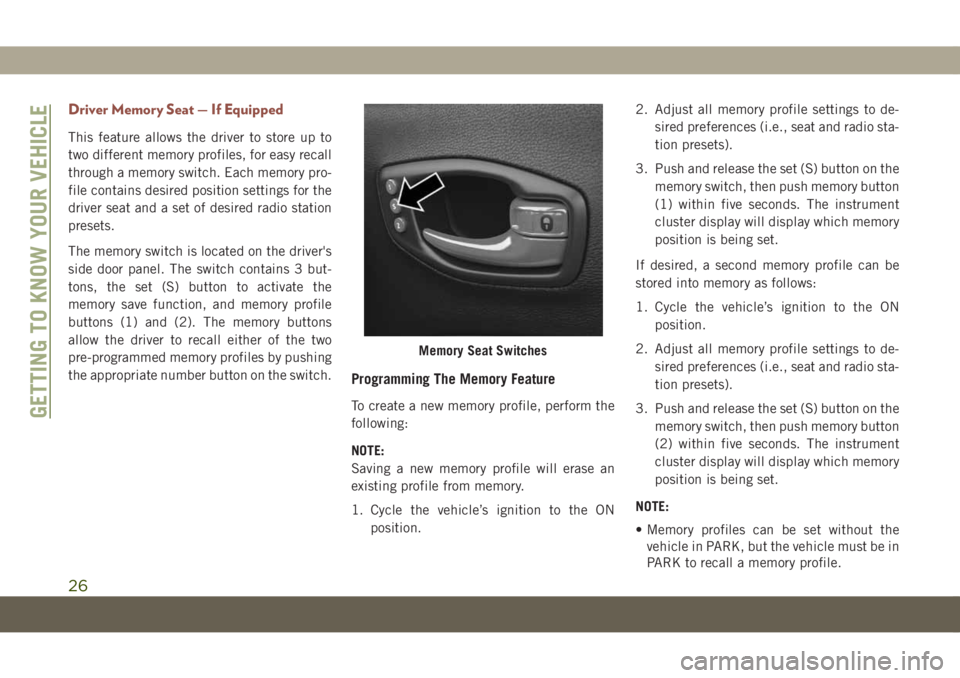
The memory switch is located on the driver's
side door panel. The switch contains 3 but-
tons, the set (S) button to activate the
memory save function, and memory profile
buttons (1) and (2). The memory buttons
allow the driver to recall either of the two
pre-programmed memory profiles by pushing
the appropriate number button on the switch.
Programming The Memory Feature
To create a new memory profile, perform the
following:
NOTE:
Saving a new memory profile will erase an
existing profile from memory.
1. Cycle the vehicle’s ignition to the ON
position.2. Adjust all memory profile settings to de-
sired preferences (i.e., seat and radio sta-
tion presets).
3. Push and release the set (S) button on the
memory switch, then push memory button
(1) within five seconds. The instrument
cluster display will display which memory
position is being set.
If desired, a second memory profile can be
stored into memory as follows:
1. Cycle the vehicle’s ignition to the ON
position.
2. Adjust all memory profile settings to de-
sired preferences (i.e., seat and radio sta-
tion presets).
3. Push and release the set (S) button on the
memory switch, then push memory button
(2) within five seconds. The instrument
cluster display will display which memory
position is being set.
NOTE:
• Memory profiles can be set without the
vehicle in PARK, but the vehicle must be in
PARK to recall a memory profile.
Memory Seat Switches
GETTING TO KNOW YOUR VEHICLE
26
Page 30 of 362
NOTE:
The Easy Entry/Exit feature is not enabled
when the vehicle is delivered from the fac-
tory. The Easy Entry/Exit feature is enabled
(or later disabled) through the programmable
features in the Uconnect system.
Refer to “Uconnect Settings/Customer Pro-
grammable Features” in “Multimedia” in the
Owner’s Manual for further information.
Front Heated Seats — If Equipped
The front heated seats control buttons are
located within the Uconnect system. You can
gain access to the control buttons through
the climate screen or the controls screen.
• Press the heated seat button
once to
turn the HI setting on.
• Press the heated seat button
a second
time to turn the LO setting on.
• Press the heated seat button
a third
time to turn the heating elements off.If your vehicle is equipped with automatic
temperature controls with an integrated cen-
ter stack, or manual temperature controls,
you’ll find the heated seat switches on the
switch bank below the radio screen.
If the HI level setting is selected, the system
will automatically switch to LO level after
approximately 60 minutes of continuous op-
eration. At that time, the display will change
from HI to LO, indicating the change. The LO
level setting will turn off automatically after
approximately 45 minutes.
NOTE:
The engine must be running for the heated
seats to operate.
Vehicles With Remote Start — If Equipped
On models that are equipped with remote
start, the heated seats can be programmed to
come on during a remote start.This feature can be programmed through the
Uconnect system. Refer to “Uconnect Set-
tings” in “Multimedia” in the Owner’s
Manual for further information.
WARNING!
• Persons who are unable to feel pain to
the skin because of advanced age,
chronic illness, diabetes, spinal cord in-
jury, medication, alcohol use, exhaus-
tion or other physical condition must
exercise care when using the seat
heater. It may cause burns even at low
temperatures, especially if used for long
periods of time.
• Do not place anything on the seat or
seatback that insulates against heat,
such as a blanket or cushion. This may
cause the seat heater to overheat. Sit-
ting in a seat that has been overheated
could cause serious burns due to the
increased surface temperature of the
seat.
GETTING TO KNOW YOUR VEHICLE
28
Page 41 of 362
The Rain Sensing system has protection fea-
tures for the wiper blades and arms, and will
not operate under the following conditions:
•Change In Ignition Position— If the vehicle
is in Rain Sensing mode and the ignition is
cycled from OFF to ON, the auto wiper will
be suppressed until vehicle speed is greater
than 3 mph (5 km/h), or the wiper switch is
moved out of and back into the Intermittent
wipe position.
•Transmission In NEUTRAL Position— The
Rain Sensing system will not operate if the
NEUTRAL gear is selected at speeds of
3 mph (5 km/h) or less unless the wiper
switch is moved or the gear selector is
moved out of NEUTRAL.
Remote Start Mode Inhibit— On vehicles
equipped with Remote Starting system, Rain
Sensing wipers are not operational when the
vehicle is in the remote start mode. Once the
operator is in the vehicle and has placed the
ignition switch in the ON/RUN position, Rain
Sensing wiper operation can resume, if it has
been selected, and no other inhibit condi-
tions (mentioned previously) exist.Rear Window Wiper/Washer
The rear wiper/washer controls are located on
the windshield wiper/washer lever on the
right side of the steering column. The rear
wiper/washer is operated by rotating a switch,
located at the middle of the lever.
Rotate the center portion of the lever upward
to the first detent for intermittent operation
and to the second detent for continuous rear
wiper operation.
To use the washer, push the lever forward and
hold while spray is desired. If the lever is
pushed while the wiper is in the off position,
the wiper will operate for several wipe cycles,
then turn off.
CLIMATE CONTROLS
The Climate Control System allows you to
regulate the temperature, air flow, and direc-
tion of air circulating throughout the vehicle.
The controls are located on the touchscreen
(if equipped) and on the instrument panel
below the radio.
Automatic Climate Controls Overview
The controls for the heating and air condi-
tioning system in this vehicle can consist of a
series of outer rotary dials, inner push knobs,
and/or a touchscreen. These comfort controls
can be set to obtain desired interior condi-
tions.
39
Page 81 of 362
SAFETY FEATURES
Anti-Lock Brake System (ABS)
The Anti-Lock Brake System (ABS) provides
increased vehicle stability and brake perfor-
mance under most braking conditions. The
system automatically prevents wheel lock,
and enhances vehicle control during braking.
The ABS performs a self-check cycle to en-
sure that the ABS is working properly each
time the vehicle is started and driven. During
this self-check, you may hear a slight clicking
sound as well as some related motor noises.
ABS is activated during braking when the
system detects one or more wheels begin to
lock. Road conditions such as ice, snow,
gravel, bumps, railroad tracks, loose debris,
or panic stops may increase the likelihood of
ABS activation(s).
You also may experience the following when
ABS activates:
• The ABS motor noise (it may continue to
run for a short time after the stop).
• The clicking sound of solenoid valves.• Brake pedal pulsations.
• A slight drop of the brake pedal at the end
of the stop.
These are all normal characteristics of ABS.
WARNING!
• The ABS contains sophisticated elec-
tronic equipment that may be suscep-
tible to interference caused by improp-
erly installed or high output radio
transmitting equipment. This interfer-
ence can cause possible loss of anti-lock
braking capability. Installation of such
equipment should be performed by
qualified professionals.
• Pumping of the Anti-Lock Brakes will
diminish their effectiveness and may
lead to a collision. Pumping makes the
stopping distance longer. Just press
firmly on your brake pedal when you
need to slow down or stop.
• The ABS cannot prevent the natural laws
of physics from acting on the vehicle,
nor can it increase braking or steering
efficiency beyond that afforded by the
WARNING!
condition of the vehicle brakes and tires
or the traction afforded.
• The ABS cannot prevent collisions, in-
cluding those resulting from excessive
speed in turns, following another vehicle
too closely, or hydroplaning.
• The capabilities of an ABS equipped
vehicle must never be exploited in a
reckless or dangerous manner that could
jeopardize the user’s safety or the safety
of others.
ABS is designed to function with the OEM
tires. Modification may result in degraded
ABS performance.
Anti-Lock Brake Warning Light
The yellow “Anti-Lock Brake Warning Light”
will turn on when the ignition is turned to the
ON/RUN mode and may stay on for as long as
four seconds.
If the “Anti-Lock Brake Warning Light” re-
mains on or comes on while driving, it indi-
cates that the anti-lock portion of the brake
system is not functioning and that service is
79
Page 91 of 362
when the vehicle speed reaches approxi-
mately 6 mph (10 km/h) or higher and will
alert the driver of vehicles in these areas.
NOTE:
• The BSM system does NOT alert the driver
about rapidly approaching vehicles that are
outside the detection zones.
• The BSM system detection zone DOES NOT
change if your vehicle is towing a trailer.
Therefore, visually verify the adjacent lane
is clear for both your vehicle and trailer
before making a lane change. If the trailer
or other object (i.e., bicycle, sports equip-
ment) extends beyond the side of your ve-
hicle, this may result in the BSM warning
light remaining illuminated the entire time
the vehicle is in a forward gear. It may be
necessary to deactivate the BSM system
manually to avoid miss-detection. Refer to
“Uconnect Settings” in “Multimedia” in
the Owner’s Manual for further information.• The Blind Spot Monitoring (BSM) system
may experience drop outs (blinking on and
off) of the side mirror Warning Indicator
lamps when a motorcycle or any small ob-
ject remains at the side of the vehicle for
extended periods of time (more than a
couple of seconds).
The area on the rear fascia where the radar
sensors are located must remain free of snow,
ice, and dirt/road contamination so that the
BSM system can function properly. Do not
block the area of the rear fascia where the
radar sensors are located with foreign objects
(bumper stickers, bicycle racks, etc.)
The BSM system will provide a visual alert in
the appropriate side view mirror based on a
detected object. If the turn signal is then
activated, and it corresponds to an alert pres-
ent on that side of the vehicle, an audible
chime will also be sounded. Whenever a turn
signal and detected object are present on the
same side at the same time, both the visual
and audio alerts will be issued. In addition to
the audible alert the radio (if on) will also be
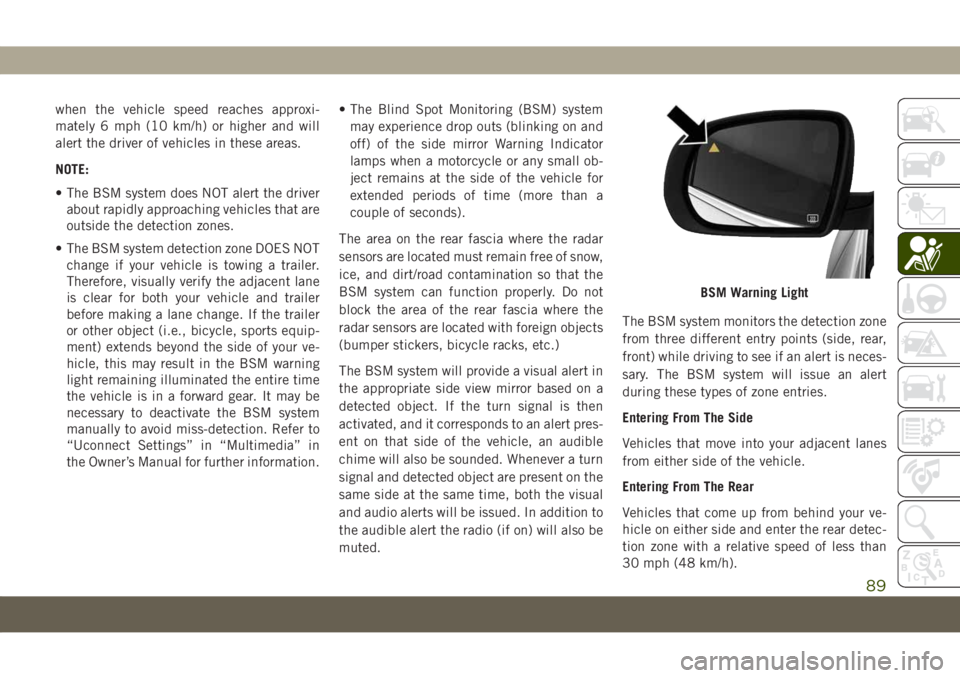
muted.The BSM system monitors the detection zone
from three different entry points (side, rear,
front) while driving to see if an alert is neces-
sary. The BSM system will issue an alert
during these types of zone entries.
Entering From The Side
Vehicles that move into your adjacent lanes
from either side of the vehicle.
Entering From The Rear
Vehicles that come up from behind your ve-
hicle on either side and enter the rear detec-
tion zone with a relative speed of less than
30 mph (48 km/h).
BSM Warning Light
89
Page 92 of 362
Overtaking Traffic
If you pass another vehicle slowly with a
relative speed less than 10 mph (16 km/h)
and the vehicle remains in the blind spot for
approximately 1.5 seconds, the warning light
will be illuminated. If the difference in speed
between the two vehicles is greater than
10 mph (16 km/h), the warning light will not
illuminate.
The BSM system is designed not to issue an
alert on stationary objects such as guardrails,
posts, walls, foliage, berms, etc. However,
occasionally the system may alert on such
objects. This is normal operation and your
vehicle does not require service.
The BSM system will not alert you of objects
that are traveling in the opposite direction of
the vehicle in adjacent lanes.
NOTE:
The BSM system may experience drop outs
(blinking on and off) in the side mirror LED
icons while a motorcycle, or any small target,
remains at the vehicle’s B-pillar for an ex-
tended period of time (longer than a couple of
seconds).WARNING!
The Blind Spot Monitoring system is only
an aid to help detect objects in the blind
spot zones. The BSM system is not de-
signed to detect pedestrians, bicyclists, or
animals. Even if your vehicle is equipped
with the BSM system, always check your
vehicle’s mirrors, glance over your shoul-
der, and use your turn signal before chang-
ing lanes. Failure to do so can result in
serious injury or death.
Rear Cross Path (RCP)
The Rear Cross Path (RCP) feature is in-
tended to aid the driver when backing out of
parking spaces where their vision of oncom-
ing vehicles may be blocked. Proceed slowly
and cautiously out of the parking space until
the rear end of the vehicle is exposed. The
RCP system will then have a clear view of the
cross traffic and if an oncoming vehicle is
detected, alert the driver.
RCP monitors the rear detection zones on
both sides of the vehicle, for objects that are
moving toward the side of the vehicle with a
minimum speed of approximately 3 mph(5 km/h), to objects moving a maximum of
approximately 20 mph (32 km/h), such as in
parking lot situations.
NOTE:
In a parking lot situation, oncoming vehicles
can be obscured by vehicles parked on either
side. If the sensors are blocked by other
structures or vehicles, the system will not be
able to alert the driver.
When RCP is on and the vehicle is in RE-
VERSE, the driver is alerted using both the
visual and audible alarms, including reduc-
ing the radio volume.
WARNING!
Rear Cross Path Detection (RCP) is not a
back up aid system. It is intended to be
used to help a driver detect an oncoming
vehicle in a parking lot situation. Drivers
must be careful when backing up, even
when using RCP. Always check carefully
behind your vehicle, look behind you, and
be sure to check for pedestrians, animals,
other vehicles, obstructions, and blind
spots before backing up. Failure to do so
can result in serious injury or death.
SAFETY
90
Page 93 of 362
Modes Of Operation
Three selectable modes of operation are
available in the Uconnect System. Refer to
“Uconnect Settings” in “Multimedia” in the
Owner’s Manual for further information.
Blind Spot Alert Lights Only (Default Setting)
When operating in Blind Spot Alert mode, the
BSM system will provide a visual alert in the
appropriate side view mirror based on a de-
tected object. However, when the system is
operating in Rear Cross Path (RCP) mode, the
system will respond with both visual and
audible alerts when a detected object is pres-
ent. Whenever an audible alert is requested,
the radio is muted.
Blind Spot Alert Lights/Chime
When operating in Blind Spot Alert Lights/
Chime mode, the BSM system will provide a
visual alert in the appropriate side view mirror
based on a detected object. If the turn signal
is then activated, and it corresponds to an
alert present on that side of the vehicle, an
audible chime will also be sounded. When-
ever a turn signal and detected object are
present on the same side at the same time,both the visual and audible alerts will be
issued. In addition to the audible alert the
radio (if on) will also be muted.
NOTE:
Whenever an audible alert is requested by the
BSM system, the radio is also muted.
When the system is in RCP, the system shall
respond with both visual and audible alerts
when a detected object is present. Whenever
an audible alert is requested, the radio vol-
ume is reduced. Turn/hazard signal status is
ignored; the RCP state always requests the
chime.
Blind Spot Alert Off
When the BSM system is turned off there will
be no visual or audible alerts from either the
BSM or RCP systems.
NOTE:
The BSM system will store the current oper-
ating mode when the vehicle is shut off. Each
time the vehicle is started the previously
stored mode will be recalled and used.Blocked Sensor
If the system detects degraded performance
due to contamination or foreign objects, a
message will warn you of a blocked sensor
and the warning indicators in side view mir-
rors will be illuminated. The warning indica-
tors will remain illuminated until blockage
clearing conditions are met. First clear the
fascia area around the sensors of the block-
age. After removing the blockage, reset the
system by cycling the ignition from ON to OFF
and then back ON.
Forward Collision Warning (FCW)
With Mitigation — If Equipped
Forward Collision Warning (FCW)
With Mitigation Operation
The Forward Collision Warning (FCW) system
with mitigation provides the driver with au-
dible warnings, visual warnings (within the
instrument cluster display), and may apply a
brake jerk to warn the driver when it detects a
potential frontal collision. The warnings and
limited braking are intended to provide the
driver with enough time to react, avoid or
mitigate the potential collision.
91
Page 98 of 362
Tire Pressure Monitoring Low Pressure
Warnings
The Tire Pressure Monitoring System
Warning Light will illuminate in the
instrument cluster and a chime will
sound when tire pressure is low in one or
more of the four active road tires. In addition,
the instrument cluster will display a "Tire
Low" message and a graphic showing the
pressure values of each tire with the low tire
pressure values highlighted or in a different
color.
Should this occur, you should stop as soon as
possible and inflate the tires with low pres-
sure (those highlighted or in a different color
in the instrument cluster display graphic) to
the vehicle’s recommended cold placard
pressure value. Once the system receives the
updated tire pressures, the system will auto-
matically update, the pressure values in the
graphic display in the instrument cluster will
stop being highlighted or return to their origi-
nal color, and the Tire Pressure Monitoring
System Warning Light will turn off.NOTE:
When filling warm tires, the tire pressure may
need to be increased up to an additional 4 psi
(28 kPa) above the recommended cold plac-
ard pressure in order to turn the Tire Pressure
Monitoring System Warning Light off. The
vehicle may need to be driven for up to
10 minutes above 15 mph (24 km/h) in order
for the TPMS to receive this information.
Service TPMS Warning
When a system fault is detected, the Tire
Pressure Monitoring System Warning Light
will flash on and off for 75 seconds and then
remain on solid. The system fault will also
sound a chime. In addition, the instrument
cluster will display a "SERVICE TPM SYS-
TEM" message for a minimum of five seconds
and then display dashes (- -) in place of the
pressure value to indicate which sensor is not
being received.
If the ignition key is cycled, this sequence
will repeat, providing the system fault still
exists. If the system fault no longer exists, the
Tire Pressure Monitoring System Warning
Light will no longer flash, and the “SERVICE
TPM SYSTEM” message will no longer dis-play, and a pressure value will display in
place of the dashes. A system fault can occur
due to any of the following:
• Jamming due to electronic devices or driv-
ing next to facilities emitting the same
radio frequencies as the TPMS sensors.
• Installing some form of aftermarket window
tinting that affects radio wave signals.
• Lots of snow or ice around the wheels or
wheel housings.
• Using tire chains on the vehicle.
• Using wheels/tires not equipped with
TPMS sensors.
Vehicles With Compact Spare or Non-Matching
Full Size Spare
1. The compact spare tire or non-matching
full size does not have a tire pressure
monitoring sensor. Therefore, the TPMS
will not monitor the pressure in the com-
pact or non-matching full size spare tire.
2. If you install the compact or non-
matching full size spare tire in place of a
road tire that has a pressure below the
low-pressure warning limit, upon the next
ignition key cycle, the Tire Pressure Moni-
SAFETY
96
Page 117 of 362
WARNING!
• Children 12 years or younger should
always ride buckled up in the rear seat of
a vehicle with a rear seat.
Knee Impact Bolsters
The Knee Impact Bolsters help protect the
knees of the driver and front passenger, and
position the front occupants for improved
interaction with the front air bags.
WARNING!
• Do not drill, cut, or tamper with the knee
impact bolsters in any way.
• Do not mount any accessories to the
knee impact bolsters such as alarm
lights, stereos, citizen band radios, etc.
Supplemental Seat-Mounted Side Air Bags
(SABs) (If Equipped)
Your vehicle may be equipped with Supple-
mental Seat-Mounted Side Air Bags (SABs).If your vehicle is equipped with Supplemen-
tal Seat-Mounted Side Air Bags (SABs),
please refer to the information below.
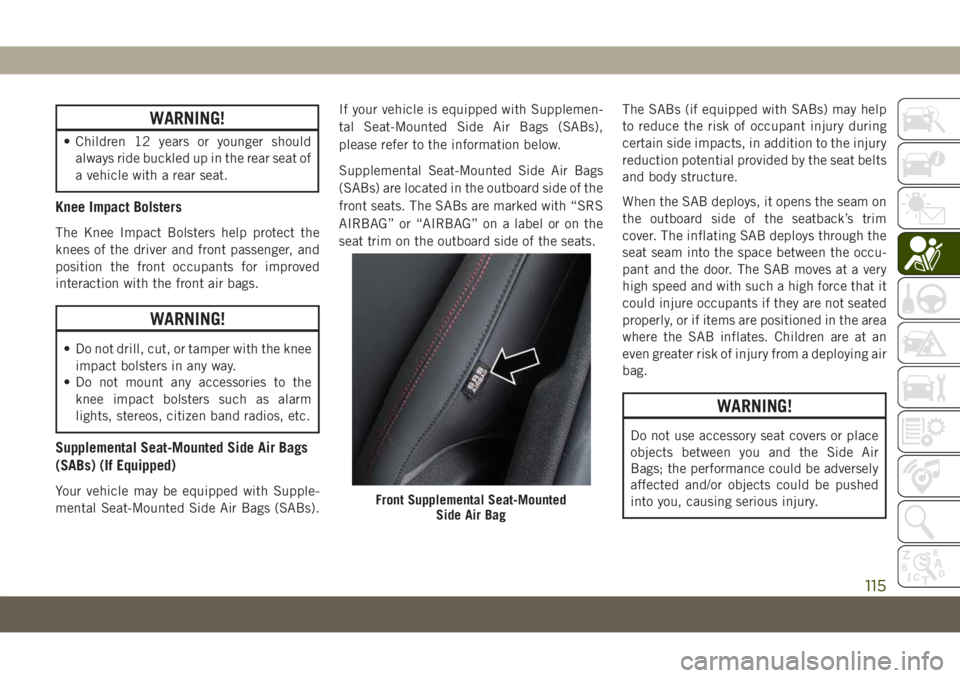
Supplemental Seat-Mounted Side Air Bags
(SABs) are located in the outboard side of the
front seats. The SABs are marked with “SRS
AIRBAG” or “AIRBAG” on a label or on the
seat trim on the outboard side of the seats.The SABs (if equipped with SABs) may help
to reduce the risk of occupant injury during
certain side impacts, in addition to the injury
reduction potential provided by the seat belts
and body structure.
When the SAB deploys, it opens the seam on
the outboard side of the seatback’s trim
cover. The inflating SAB deploys through the
seat seam into the space between the occu-
pant and the door. The SAB moves at a very
high speed and with such a high force that it
could injure occupants if they are not seated
properly, or if items are positioned in the area
where the SAB inflates. Children are at an
even greater risk of injury from a deploying air
bag.
WARNING!
Do not use accessory seat covers or place
objects between you and the Side Air
Bags; the performance could be adversely
affected and/or objects could be pushed
into you, causing serious injury.
Front Supplemental Seat-Mounted
Side Air Bag
115