window JEEP COMPASS 2019 Owner handbook (in English)
[x] Cancel search | Manufacturer: JEEP, Model Year: 2019, Model line: COMPASS, Model: JEEP COMPASS 2019Pages: 362, PDF Size: 6.23 MB
Page 8 of 362
WELCOME FROM FCA
HOW TO FIND YOUR OWNER’S MANUAL ONLINE.... 1
HOW TO USE THIS MANUAL
HOW TO USE THIS MANUAL............... 2Essential Information................ 2
Symbols........................ 2
ROLLOVER WARNING................... 2
IMPORTANT NOTICE................... 3
WARNINGS AND CAUTIONS............... 4
VEHICLE CHANGES/ALTERATIONS............ 4
GRAPHICAL TABLE OF CONTENTS
INSTRUMENT PANEL.................. 11
INTERIOR......................... 12
GETTING TO KNOW YOUR VEHICLE
KEYS........................... 13Key Fobs...................... 13
IGNITION SWITCH.................... 15Keyless Enter-N-Go — Ignition —
If Equipped..................... 15
Integrated/Manual Ignition — If Equipped . . 16
Electronic Steering Wheel Lock —
If Equipped..................... 16
Mechanical Steering Wheel Lock —
If Equipped..................... 16
REMOTE STARTING SYSTEM — IF EQUIPPED.... 17How To Use Remote Start — If Equipped . . . 17
To Enter Remote Start Mode........... 18
VEHICLE SECURITY ALARM — IF EQUIPPED..... 18To Arm The System................ 18
To Disarm The System.............. 19
Security System Manual Override........ 19
PREMIUM VEHICLE SECURITY ALARM —
IF EQUIPPED...................... 19
To Arm The System................ 20
To Disarm The System.............. 20
Security System Manual Override........ 21
DOORS.......................... 21Keyless Enter-N-Go — Passive Entry...... 21
Child-Protection Door Lock System —
Rear Doors..................... 23
SEATS .......................... 24Manual Adjustment (Rear Seats)........ 24
Driver Memory Seat — If Equipped....... 26
Front Heated Seats — If Equipped....... 28
Front Ventilated Seats — If Equipped..... 29
40/20/40 Rear Seat Armrest— If Equipped . 29
HEAD RESTRAINTS................... 29Front Head Restraint Adjustment........ 30
Rear Head Restraints............... 31
STEERING WHEEL................... 32Tilt/Telescoping Steering Column........ 32
Heated Steering Wheel — If Equipped..... 32
EXTERIOR LIGHTS.................... 33Multifunction Lever................ 33
Headlight Switch.................. 33
Daytime Running Lights (DRL) —
If Equipped..................... 34
High/Low Beam Switch.............. 34
Automatic High Beam Headlamp Control —
If Equipped..................... 34
Flash-To-Pass................... 34
Automatic Headlights — If Equipped..... 34
Headlight Time Delay............... 35
Lights-On Reminder — If Equipped...... 35
Front And Rear Fog Lights — If Equipped . . . 35
Turn Signals.................... 36Headlight Leveling System — If Equipped . . 36
Battery Saver Feature............... 36
WINDSHIELD WIPERS AND WASHERS......... 37Windshield Wiper Operation........... 37
Rain Sensing Wipers — If Equipped...... 38
Rear Window Wiper/Washer........... 39
CLIMATE CONTROLS................... 39Automatic Climate Controls Overview..... 39
Automatic Temperature Control (ATC)..... 47
Operating Tips................... 47
WINDOWS........................ 48Power Window Controls.............. 48
Auto-Down Feature................ 49
Auto-Up Feature With Anti-Pinch Protection . 49
Window Lockout Switch............. 49
Wind Buffeting.................. 50
POWER SUNROOF WITH POWER SHADE —
IF EQUIPPED....................... 50
Opening Sunroof.................. 51
Opening Sunroof — Vent............. 51
Closing Sunroof.................. 51
Opening Power Shade............... 51
Closing Power Shade............... 52
Pinch Protect Feature............... 52
Sunroof Maintenance............... 52
Ignition Off Operation............... 53
HOOD.......................... 53Opening The Hood................. 53
Closing The Hood................. 53
LIFTGATE......................... 54Opening....................... 54
Closing........................ 54
Power Liftgate — If Equipped.......... 54
INTERNAL EQUIPMENT................. 56Power Outlets.................... 56
TABLE OF CONTENTS
6
Page 14 of 362
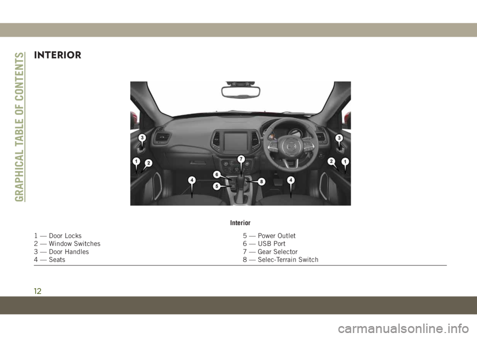
INTERIOR
Interior
1 — Door Locks 5 — Power Outlet
2 — Window Switches 6 — USB Port
3 — Door Handles 7 — Gear Selector
4 — Seats 8 — Selec-Terrain Switch
GRAPHICAL TABLE OF CONTENTS
12
Page 17 of 362
IGNITION SWITCH
Keyless Enter-N-Go — Ignition —
If Equipped
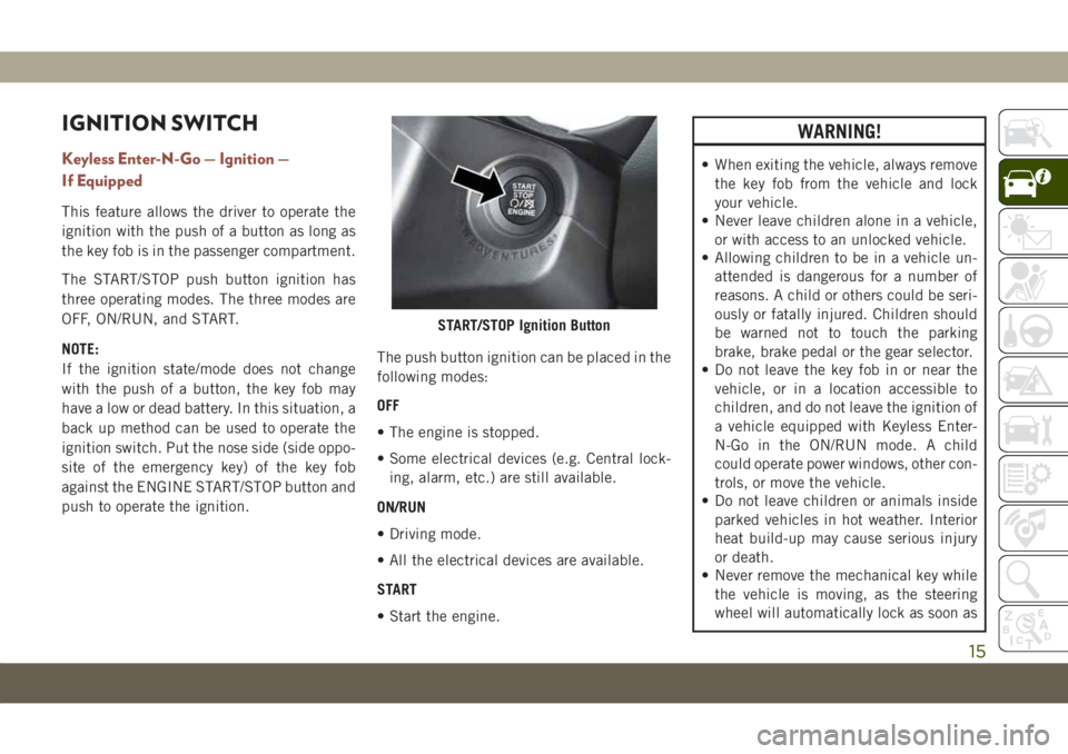
This feature allows the driver to operate the
ignition with the push of a button as long as
the key fob is in the passenger compartment.
The START/STOP push button ignition has
three operating modes. The three modes are
OFF, ON/RUN, and START.
NOTE:
If the ignition state/mode does not change
with the push of a button, the key fob may
have a low or dead battery. In this situation, a
back up method can be used to operate the
ignition switch. Put the nose side (side oppo-
site of the emergency key) of the key fob
against the ENGINE START/STOP button and
push to operate the ignition.The push button ignition can be placed in the
following modes:
OFF
• The engine is stopped.
• Some electrical devices (e.g. Central lock-
ing, alarm, etc.) are still available.
ON/RUN
• Driving mode.
• All the electrical devices are available.
START
• Start the engine.
WARNING!
• When exiting the vehicle, always remove
the key fob from the vehicle and lock
your vehicle.
• Never leave children alone in a vehicle,
or with access to an unlocked vehicle.
• Allowing children to be in a vehicle un-
attended is dangerous for a number of
reasons. A child or others could be seri-
ously or fatally injured. Children should
be warned not to touch the parking
brake, brake pedal or the gear selector.
• Do not leave the key fob in or near the
vehicle, or in a location accessible to
children, and do not leave the ignition of
a vehicle equipped with Keyless Enter-
N-Go in the ON/RUN mode. A child
could operate power windows, other con-
trols, or move the vehicle.
• Do not leave children or animals inside
parked vehicles in hot weather. Interior
heat build-up may cause serious injury
or death.
• Never remove the mechanical key while
the vehicle is moving, as the steering
wheel will automatically lock as soon as
START/STOP Ignition Button
15
Page 20 of 362
WARNING!
• Keep key fobs away from children. Op-
eration of the Remote Start System, win-
dows, door locks or other controls could
cause serious injury or death.
To Enter Remote Start Mode
Push and release the remote start button on
the key fob twice within five seconds. The
vehicle doors will lock, the parking lights will
flash, and the horn will chirp twice (if pro-
grammed). Then, the engine will start, and
the vehicle will remain in the Remote Start
mode for a 15-minute cycle.
NOTE:
• If an engine fault is present or fuel level is
low, the vehicle will start and then shut
down in 10 seconds.
• The park lamps will turn on and remain on
during Remote Start mode.
• For security, power window and power sun-
roof operation (if equipped) are disabled
when the vehicle is in the Remote Start
mode.• The engine can be started two consecutive
times with the key fob. However, the igni-
tion must be cycled by pushing the START/
STOP button twice (or the ignition switch
must be cycled to the ON/RUN position)
before you can repeat the start sequence
for a third cycle.
VEHICLE SECURITY ALARM
— IF EQUIPPED
The vehicle security alarm monitors the ve-
hicle doors, hood, liftgate, and the Keyless
Enter-N-Go — Ignition for unauthorized op-
eration. While the vehicle security alarm is
armed, interior switches for door locks and
liftgate release are disabled. If something
triggers the alarm, the vehicle security alarm
will provide the following audible and visible
signals:
• The horn will pulse
• The turn signals will flash
• The vehicle security light in the instrument
cluster will flash
To Arm The System
Follow these steps to arm the vehicle security
alarm:
1. Make sure the vehicle’s ignition is placed
in the “OFF” mode.
• For vehicles equipped with Keyless En-
try, make sure the vehicle’s keyless
ignition system is OFF.
2. Perform one of the following methods to
lock the vehicle:
• Push the lock button on the interior
power door lock switch with the driver
and/or passenger door open.
• Push the lock button on the exterior
Passive Entry Door Handle with a valid
key fob available in the same exterior
zone, refer to "Doors" in "Getting To
Know Your Vehicle" in the Owner’s
Manual at for further information.
•
Push the lock button on the exterior Pas-
sive Entry Door Handle with a valid key
fob available in the same exterior zone.
• Push the lock button on the key fob.
3. If any doors are open, close them.
GETTING TO KNOW YOUR VEHICLE
18
Page 26 of 362
NOTE:
• When the child lock system is engaged, the
door can be opened only by using the out-
side door handle even though the inside
door lock is in the unlocked position.
• After disengaging the Child-Protection
Door Lock system, always test the door from
the inside to make certain it is in the
desired position.
• After engaging the Child-Protection Door
Lock system, always test the door from the
inside to make certain it is in the desired
position.
• For emergency exit with the system en-
gaged, rotate the door lock button until the
lock indicator is hidden (unlocked posi-
tion), roll down the window, and open the
door with the outside door handle.WARNING!
Avoid trapping anyone in a vehicle in a
collision. Remember that the rear doors
can only be opened from the outside when
the Child-Protection locks are engaged
(locked).
NOTE:
Always use this device when carrying chil-
dren. After engaging the child lock on both
rear doors, check for effective engagement by
trying to open a door with the internal handle.
Once the child protection door lock system is
engaged, it is impossible to open the doors
from inside the vehicle. Before getting out of
the car, be sure to check that there is no one
left inside.
SEATS
Seats are a part of the Occupant Restraint
System of the vehicle.
WARNING!
•It is dangerous to ride in a cargo area,
inside or outside of a vehicle. In a collision,
people riding in these areas are more likely
to be seriously injured or killed.
• Do not allow people to ride in any area of
your vehicle that is not equipped with
seats and seat belts. In a collision,
people riding in these areas are more
likely to be seriously injured or killed.
• Be sure everyone in your vehicle is in a
seat and using a seat belt properly.
Manual Adjustment (Rear Seats)
WARNING!
Do not pile luggage or cargo higher than
the top of the seatback. This could impair
visibility or become a dangerous projectile
in a sudden stop or collision.
GETTING TO KNOW YOUR VEHICLE
24
Page 39 of 362
WINDSHIELD WIPERS
AND WASHERS
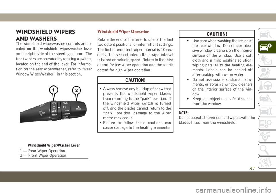
The windshield wiper/washer controls are lo-
cated on the windshield wiper/washer lever
on the right side of the steering column. The
front wipers are operated by rotating a switch,
located on the end of the lever. For informa-
tion on the rear wiper/washer, refer to “Rear
Window Wiper/Washer” in this section.
Windshield Wiper Operation
Rotate the end of the lever to one of the first
two detent positions for intermittent settings.
The first intermittent wiper interval is 10 sec-
onds. The second intermittent wipe interval
is based on vehicle speed. Rotate to the third
detent for low wiper operation and the fourth
detent for high wiper operation.
CAUTION!
• Always remove any buildup of snow that
prevents the windshield wiper blades
from returning to the “park” position. If
the windshield wiper switch is turned
off, and the blades cannot return to the
“park” position, damage to the wiper
motor may occur.
• Failure to follow these cautions can
cause damage to the heating elements:
CAUTION!
• Use care when washing the inside of
the rear window. Do not use abra-
sive window cleaners on the interior
surface of the window. Use a soft
cloth and a mild washing solution,
wiping parallel to the heating ele-
ments. Labels can be peeled off
after soaking with warm water.
• Do not use scrapers, sharp instru-
ments, or abrasive window cleaners
on the interior surface of the win-
dow.
• Keep all objects a safe distance
from the window.
NOTE:
Do not operate the windshield wipers with the
blades lifted from the windshield.
Windshield Wiper/Washer Lever
1 — Rear Wiper Operation
2 — Front Wiper Operation
37
Page 41 of 362
The Rain Sensing system has protection fea-
tures for the wiper blades and arms, and will
not operate under the following conditions:
•Change In Ignition Position— If the vehicle
is in Rain Sensing mode and the ignition is
cycled from OFF to ON, the auto wiper will
be suppressed until vehicle speed is greater
than 3 mph (5 km/h), or the wiper switch is
moved out of and back into the Intermittent
wipe position.
•Transmission In NEUTRAL Position— The
Rain Sensing system will not operate if the
NEUTRAL gear is selected at speeds of
3 mph (5 km/h) or less unless the wiper
switch is moved or the gear selector is
moved out of NEUTRAL.
Remote Start Mode Inhibit— On vehicles
equipped with Remote Starting system, Rain
Sensing wipers are not operational when the
vehicle is in the remote start mode. Once the
operator is in the vehicle and has placed the
ignition switch in the ON/RUN position, Rain
Sensing wiper operation can resume, if it has
been selected, and no other inhibit condi-
tions (mentioned previously) exist.Rear Window Wiper/Washer
The rear wiper/washer controls are located on
the windshield wiper/washer lever on the
right side of the steering column. The rear
wiper/washer is operated by rotating a switch,
located at the middle of the lever.
Rotate the center portion of the lever upward
to the first detent for intermittent operation
and to the second detent for continuous rear
wiper operation.
To use the washer, push the lever forward and
hold while spray is desired. If the lever is
pushed while the wiper is in the off position,
the wiper will operate for several wipe cycles,
then turn off.
CLIMATE CONTROLS
The Climate Control System allows you to
regulate the temperature, air flow, and direc-
tion of air circulating throughout the vehicle.
The controls are located on the touchscreen
(if equipped) and on the instrument panel
below the radio.
Automatic Climate Controls Overview
The controls for the heating and air condi-
tioning system in this vehicle can consist of a
series of outer rotary dials, inner push knobs,
and/or a touchscreen. These comfort controls
can be set to obtain desired interior condi-
tions.
39
Page 45 of 362
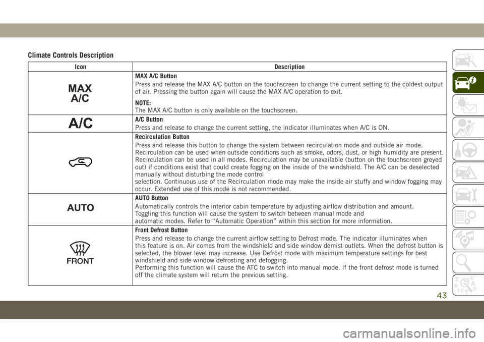
Climate Controls Description
Icon Description
MAX A/C Button
Press and release the MAX A/C button on the touchscreen to change the current setting to the coldest output
of air. Pressing the button again will cause the MAX A/C operation to exit.
NOTE:
The MAX A/C button is only available on the touchscreen.
A/C Button
Press and release to change the current setting, the indicator illuminates when A/C is ON.
Recirculation Button
Press and release this button to change the system between recirculation mode and outside air mode.
Recirculation can be used when outside conditions such as smoke, odors, dust, or high humidity are present.
Recirculation can be used in all modes. Recirculation may be unavailable (button on the touchscreen greyed
out) if conditions exist that could create fogging on the inside of the windshield. The A/C can be deselected
manually without disturbing the mode control
selection. Continuous use of the Recirculation mode may make the inside air stuffy and window fogging may
occur. Extended use of this mode is not recommended.
AUTO Button
Automatically controls the interior cabin temperature by adjusting airflow distribution and amount.
Toggling this function will cause the system to switch between manual mode and
automatic modes. Refer to “Automatic Operation” within this section for more information.
Front Defrost Button
Press and release to change the current airflow setting to Defrost mode. The indicator illuminates when
this feature is on. Air comes from the windshield and side window demist outlets. When the defrost button is
selected, the blower level may increase. Use Defrost mode with maximum temperature settings for best
windshield and side window defrosting and defogging.
Performing this function will cause the ATC to switch into manual mode. If the front defrost mode is turned
off the climate system will return the previous setting.
43
Page 46 of 362
Icon Description
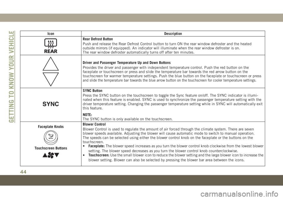
Rear Defrost Button
Push and release the Rear Defrost Control button to turn ON the rear window defroster and the heated
outside mirrors (if equipped). An indicator will illuminate when the rear window defroster is on.
The rear window defroster automatically turns off after ten minutes.
Driver and Passenger Temperature Up and Down Buttons
Provides the driver and passenger with independent temperature control. Push the red button on the
faceplate or touchscreen or press and slide the temperature bar towards the red arrow button on the
touchscreen for warmer temperature settings. Push the blue button on the faceplate or touchscreen or press
and slide the temperature bar towards the blue arrow button on the touchscreen for cooler temperature settings.
SYNC Button
Press the SYNC button on the touchscreen to toggle the Sync feature on/off. The SYNC indicator is illumi-
nated when this feature is enabled. SYNC is used to synchronize the passenger temperature setting with the
driver temperature setting. Changing the passenger temperature setting while in SYNC will automatically exit
this feature.
NOTE:
The SYNC button is only available on the touchscreen.
Faceplate Knobs
MODE
Touchscreen Buttons
Blower Control
Blower Control is used to regulate the amount of air forced through the climate system. There are seven
blower speeds available. Adjusting the blower will cause automatic mode to switch to manual operation.
The speeds can be selected using either the blower control knob on the faceplate or the buttons on the
touchscreen.
•Faceplate:The blower speed increases as you turn the blower control knob clockwise from the lowest blower
setting. The blower speed decreases as you turn the blower control knob counterclockwise.
•Touchscreen:Use the small blower icon to reduce the blower setting and the large blower icon to increase the
blower setting. Blower can also be selected by pressing the blower bar area between the icons.GETTING TO KNOW YOUR VEHICLE
44
Page 47 of 362
Icon Description
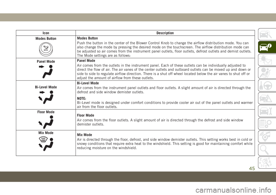
Modes Button
MODE
Modes Button
Push the button in the center of the Blower Control Knob to change the airflow distribution mode. You can
also change the mode by pressing the desired mode on the touchscreen. The airflow distribution mode can
be adjusted so air comes from the instrument panel outlets, floor outlets, defrost outlets and demist outlets.
The Mode settings are as follows:
Panel Mode
Panel Mode
Air comes from the outlets in the instrument panel. Each of these outlets can be individually adjusted to
direct the flow of air. The air vanes of the center outlets and outboard outlets can be moved up and down or
side to side to regulate airflow direction. There is a shut off wheel located below the air vanes to shut off or
adjust the amount of airflow from these outlets.
Bi-Level Mode
Bi-Level Mode
Air comes from the instrument panel outlets and floor outlets. A slight amount of air is directed through the
defrost and side window demister outlets.
NOTE:
Bi-Level mode is designed under comfort conditions to provide cooler air out of the panel outlets and warmer
air from the floor outlets.
Floor Mode
Floor Mode
Air comes from the floor outlets. A slight amount of air is directed through the defrost and side window
demister outlets.
Mix Mode
Mix Mode
Air is directed through the floor, defrost, and side window demister outlets. This setting works best in cold or
snowy conditions that require extra heat to the windshield. This setting is good for maintaining comfort while
reducing moisture on the windshield.
45