clock JEEP COMPASS 2020 Owner handbook (in English)
[x] Cancel search | Manufacturer: JEEP, Model Year: 2020, Model line: COMPASS, Model: JEEP COMPASS 2020Pages: 328, PDF Size: 8.85 MB
Page 12 of 328
10
DEALER SERVICE ................................ 227
Air Conditioner Maintenance.......... 227
Wiper Blades ............................... 228
Exhaust System ........................... 228
Cooling System ............................ 229
Brake System .............................. 230
Manual Transmission — If
Equipped ..................................... 231 Automatic Transmission ................ 231
RAISING THE VEHICLE .......................... 232TIRES ................................................. 232
Tires — General Information ......... 232
Tire Types .................................... 236
Spare Tires — If Equipped ............ 237
Tire Chains (Traction Devices) ....... 239
Tire Rotation Recommendations .... 239
STORING THE VEHICLE ......................... 240
BODYWORK ......................................... 241
Preserving The Bodywork ............... 241
INTERIORS ......................................... 242
Seats And Fabric Parts .................. 242
Plastic And Coated Parts ............... 243
Leather Parts ............................... 243
Glass Surfaces ............................ 243
TECHNICAL SPECIFICATIONS
IDENTIFICATION DATA .......................... 244
Vehicle Identification Number ....... 244
WHEEL AND TIRE TORQUE
SPECIFICATIONS ..................................244
Torque Specifications ................... 244
DIMENSIONS .......................................245
WHEELS ..............................................247
WEIGHTS ............................................249
FUEL REQUIREMENTS — GASOLINE
ENGINE ...............................................250
1.4L Turbo Gasoline Engine .......... 250
Ethanol ....................................... 250
Materials Added To Fuel ............... 250
Gasoline/Oxygenate Blends............ 250
Fuel Icon Identification Compliant To
EN16942 .................................... 251 Fuel System Cautions ................... 252
Carbon Monoxide Warnings ........... 252
FUEL REQUIREMENTS — DIESEL
ENGINE ..............................................252
Diesel Engine .............................. 252
Fuel Icon Identification Compliant To
EN16942 .................................... 253
FLUID CAPACITIES ..............................254 FLUIDS AND LUBRICANTS .....................255
Engine ........................................ 255
Chassis ...................................... 259
FUEL CONSUMPTION AND CO2
EMISSIONS ........................................260 MOPAR ACCESSORIES .........................260
Authentic Accessories By Mopar .... 260
MULTIMEDIA
UCONNECT SYSTEMS ...........................262
CYBERSECURITY .................................262
UCONNECT 3 WITH 5–INCH DISPLAY — IF
EQUIPPED............................................263
Uconnect 3 With 5–inch Display At A
Glance .........................................263 Clock Setting ...............................263
Audio Setting ...............................263
Radio Operation ...........................264
USB/Audio Jack (AUX)/Bluetooth®
Operation .....................................265 Voice Text Reply (Not Compatible With
iPhone®) ....................................266 Apps — If Equipped......................267
UCONNECT 4 WITH 7-INCH DISPLAY ....267
Uconnect 4 At A Glance ...............267
Drag & Drop Menu Bar .................268
Radio ..........................................269
Media Hub — USB/Audio Jack (AUX) —
If Equipped ..................................270 Android Auto™ — If Equipped .......271
Apple CarPlay® Integration — If
Equipped .....................................272 Apps — If Equipped......................273
2020_JEEP_M6_UG_UK.book Page 10
Page 18 of 328
GETTING TO KNOW YOUR VEHICLE
16
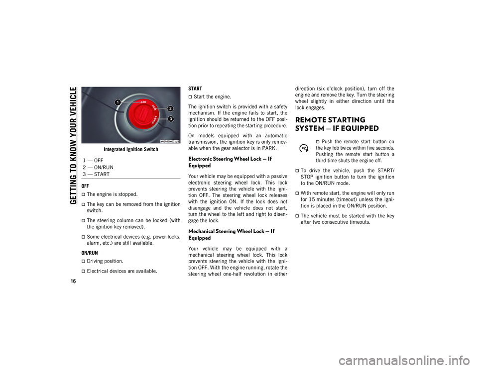
Integrated Ignition Switch
OFF
The engine is stopped.
The key can be removed from the ignition
switch.
The steering column can be locked (with
the ignition key removed).
Some electrical devices (e.g. power locks,
alarm, etc.) are still available.
ON/RUN
Driving position.
Electrical devices are available. START
Start the engine.
The ignition switch is provided with a safety
mechanism. If the engine fails to start, the
ignition should be returned to the OFF posi -
tion prior to repeating the starting procedure.
On models equipped with an automatic
transmission, the ignition key is only remov -
able when the gear selector is in PARK.
Electronic Steering Wheel Lock — If
Equipped
Your vehicle may be equipped with a passive
electronic steering wheel lock. This lock
prevents steering the vehicle with the igni -
tion OFF. The steering wheel lock releases
with the ignition ON. If the lock does not
disengage and the vehicle does not start,
turn the wheel to the left and right to disen -
gage the lock.
Mechanical Steering Wheel Lock — If
Equipped
Your vehicle may be equipped with a
mechanical steering wheel lock. This lock
prevents steering the vehicle with the igni -
tion OFF. With the engine running, rotate the
steering wheel one-half revolution in either direction (six o’clock position), turn off the
engine and remove the key. Turn the steering
wheel slightly in either direction until the
lock engages.
REMOTE STARTING
SYSTEM — IF EQUIPPED
Push the remote start button on
the key fob twice within five seconds.
Pushing the remote start button a
third time shuts the engine off.
To drive the vehicle, push the START/
STOP ignition button to turn the ignition
to the ON/RUN mode.
With remote start, the engine will only run
for 15 minutes (timeout) unless the igni -
tion is placed in the ON/RUN position.
The vehicle must be started with the key
after two consecutive timeouts.
1 — OFF
2 — ON/RUN
3 — START
2020_JEEP_M6_UG_UK.book Page 16
Page 33 of 328
31
EXTERIOR LIGHTS
Multifunction Lever
The multifunction lever controls the opera-
tion of the turn signals, headlight beam
selection and passing lights. The multifunc -
tion lever is located on the left side of the
steering column. Multifunction Lever
Headlight Switch
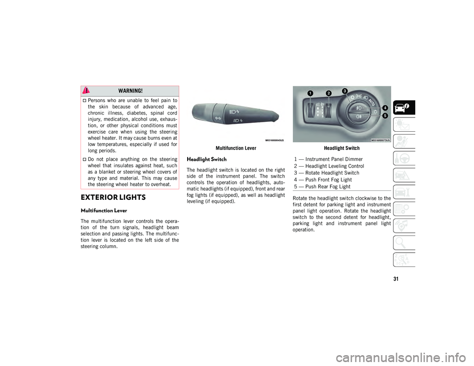
The headlight switch is located on the right
side of the instrument panel. The switch
controls the operation of headlights, auto
-
matic headlights (if equipped), front and rear
fog lights (if equipped), as well as headlight
leveling (if equipped). Headlight Switch
Rotate the headlight switch clockwise to the
first detent for parking light and instrument
panel light operation. Rotate the headlight
switch to the second detent for headlight,
parking light and instrument panel light
operation.
WARNING!
Persons who are unable to feel pain to
the skin because of advanced age,
chronic illness, diabetes, spinal cord
injury, medication, alcohol use, exhaus-
tion, or other physical conditions must
exercise care when using the steering
wheel heater. It may cause burns even at
low temperatures, especially if used for
long periods.
Do not place anything on the steering
wheel that insulates against heat, such
as a blanket or steering wheel covers of
any type and material. This may cause
the steering wheel heater to overheat.1 — Instrument Panel Dimmer
2 — Headlight Leveling Control
3 — Rotate Headlight Switch
4 — Push Front Fog Light
5 — Push Rear Fog Light
2020_JEEP_M6_UG_UK.book Page 31
Page 34 of 328
GETTING TO KNOW YOUR VEHICLE
32
Daytime Running Lights (DRL) — If
Equipped
The Daytime Running Lights will turn on
when the engine is started and remain on
unless the headlamps are turned on or the
ignition is in the OFF position.
NOTE:
If allowed by law in the country in which the
vehicle was purchased the Daytime Running
Lights can be turned on and off using the
Uconnect System. Refer to “Uconnect
Settings” in “Multimedia” in the Owner’s
Manual for further details.
High/Low Beam Switch
Push the multifunction lever toward the
instrument panel to switch the headlights to
high beams. Pulling the multifunction lever
back toward the steering wheel will return
the lights to low beams.
Automatic High Beam Headlamp Control
— If Equipped
The Automatic High Beam Headlamp Control
system provides increased forward lighting at
night by automating high beam control
through the use of a digital camera mounted
on the inside rearview mirror. This cameradetects vehicle specific light and automati
-
cally switches from high beams to low beams
until the approaching vehicle is out of view.
NOTE:
The Automatic High Beam Headlamp
Control can be turned on or off using the
Uconnect System. Refer to “Uconnect
Settings” in “Multimedia” in the Owner’s
Manual for further information.
Broken, muddy, or obstructed headlights
and taillights of vehicles in the field of
view will cause headlights to remain on
longer (closer to the vehicle). Also, dirt,
film, and other obstructions on the wind -
shield or camera lens will cause the
system to function improperly.
Flash-To-Pass
You can signal another vehicle with your
headlights by lightly pulling the multifunc -
tion lever toward you. This will cause the
high beam headlights to turn on, and remain
on, until the lever is released.
Automatic Headlights — If Equipped
This system automatically turns the head -
lights on or off according to ambient light
levels. To turn the system on, rotate the headlight switch clockwise to the last detent
for automatic headlight operation. When the
system is on, the headlight time delay
feature is also on. This means the headlights
will stay on for up to 90 seconds after you
place the ignition into the OFF position. To
turn the automatic system off, move the
headlight switch out of the AUTO position.
NOTE:
The engine must be running before the head
-
lights will come on in the automatic mode.
Headlight Time Delay
This feature provides the safety of headlight
illumination for up to 90 seconds (program -
mable) when leaving your vehicle in an unlit
area.
To activate the delay feature, place the igni -
tion in the OFF position while the headlights
are still on. Then, turn off the headlights
within 45 seconds. The delay interval begins
when the headlight switch is turned off.
If you turn the headlights or parking lights
on, or place the ignition in ACC or RUN, the
system will cancel the delay.
If you turn the headlights off before the igni -
tion, they will turn off in the normal manner.
2020_JEEP_M6_UG_UK.book Page 32
Page 43 of 328
41
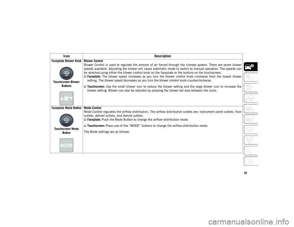
Faceplate Blower KnobTouchscreen Blower Buttons Blower Control
Blower Control is used to regulate the amount of air forced through the climate system. There are seven blower
speeds available. Adjusting the blower will cause automatic mode to switch to manual operation. The speeds can
be selected using either the blower control knob on the faceplate or the buttons on the touchscreen.
Faceplate:
The blower speed increases as you turn the blower control knob clockwise from the lowest blower
setting. The blower speed decreases as you turn the blower control knob counterclockwise.
Touchscreen: Use the small blower icon to reduce the blower setting and the large blower icon to increase the
blower setting. Blower can also be selected by pressing the blower bar area between the icons.
Faceplate Mode Button
Touchscreen Mode Button Mode Control
Mode Control regulates the airflow distribution. The airflow distribution outlets are: instrument panel outlets, floor
outlets, defrost outlets, and demist outlets.
Faceplate:
Push the Mode Button to change the airflow distribution mode.
Touchscreen: Press one of the “MODE” buttons to change the airflow distribution mode.
The Mode settings are as follows:
Icon Description
2020_JEEP_M6_UG_UK.book Page 41
Page 172 of 328
STARTING AND OPERATING
170
Refilling With Nozzles
You can fill up at any AdBlue® (UREA)
distributor.
Proceed as follows:
Insert the AdBlue® (UREA) nozzle in the
filler, start refilling and stop refilling at the
first shut-off (the shut-off indicates that
the AdBlue® (UREA) tank is full). Do not
proceed with the refilling, to prevent
spillage of AdBlue® (UREA).
Extract the nozzle.
Refilling With Containers
Proceed as follows:
Check the expiration date.
Read the advice for use on the label before
pouring the content of the bottle into the
AdBlue® (UREA) tank.
If systems which cannot be screwed in
(e.g. tanks) are used for refilling, after the
indication appears on the instrument
panel display refer to “Warning lights And
Messages" in the “Getting To Know Your
Instrument Panel” for further information,
fill the AdBlue® (UREA) tank with no
more than 2 Gallons (8 liters).
If containers which can be screwed to the
filler are used, the reservoir is full when
the AdBlue® (UREA) level in the
container stops pouring out. Do not
proceed further.
Operations After Refilling
Proceed as follows:
Fit the cap back on the AdBlue® (UREA)
filler by turning it clockwise and screwing
it completely.
Cycle the ignition to RUN (it is not neces-
sary to start the engine).
Wait for the indication on the instrument
panel to switch off before moving the car.
The indication may stay on for a few
seconds to approximately half a minute. If
the engine is started and the car is moved,
the indication will remain on for longer.
This will not compromise engine opera-
tion.
If the AdBlue® (UREA) was topped up
when the tank was empty, wait for
2 minutes before starting the engine. NOTE:
If AdBlue® (UREA) is spilled out of the
filler neck, clean up well the area and
proceed to filling up again. If the liquid
crystallizes, eliminate it with a sponge and
warm water.
DO NOT EXCEED THE MAXIMUM LEVEL:
this could cause damage to the reservoir.
AdBlue® (UREA) freezes at under 12°F
(-11°C). Although the system is designed
to operate below the freezing point of the
UREA, it is advisable not to fill the tank
beyond the maximum level because if the
UREA freezes the system can be
damaged. Follow the instructions in this
section.
If the AdBlue® (UREA) is spilled on
painted surfaces or aluminium, immedi
-
ately clean the area with water and use
absorbent material to collect the fluid that
has been spilled on the ground.
Do not try to start the engine if AdBlue®
(UREA) was accidentally added to the
diesel fuel tank, this can result in serious
engine damage, contact an authorized
dealer.
2020_JEEP_M6_UG_UK.book Page 170
Page 181 of 328
179
High Intensity Discharge (HID)
Headlamps — If Equipped
The headlamps contain a type of high voltage
discharge light source. High voltage can
remain in the circuit even with the headlamp
switch off. Because of this, you should not
attempt to service a HID headlamp light
source yourself. If an HID headlamp light
source fails, take your vehicle to an autho-
rized dealer for service.
NOTE:
On vehicles equipped with HID headlamps,
when the headlamps are turned on, there is
a blue hue to the lights. This diminishes and
becomes more white after approximately 10
seconds, as the system charges.
Replacing Exterior Bulbs
Headlamps
Hi/Lo Beam Light Halogen
The bulbs can be accessed from the wheel
liner with the following procedure:
1. Turn the front wheels completely.
2. Remove the wheel liner.
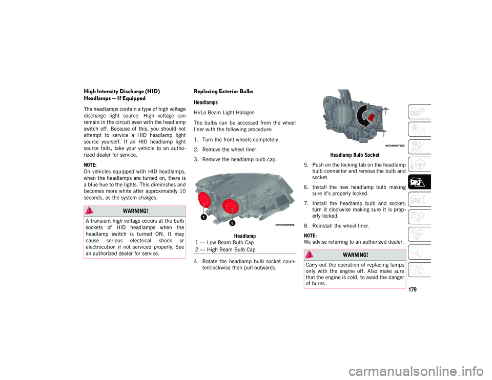
3. Remove the headlamp bulb cap.
Headlamp
4. Rotate the headlamp bulb socket coun -
terclockwise then pull outwards. Headlamp Bulb Socket
5. Push on the locking tab on the headlamp bulb connector and remove the bulb and
socket.
6. Install the new headlamp bulb making sure it’s properly locked.
7. Install the headlamp bulb and socket; turn it clockwise making sure it is prop -
erly locked.
8. Reinstall the wheel liner.
NOTE:
We advise referring to an authorized dealer.
WARNING!
A transient high voltage occurs at the bulb
sockets of HID headlamps when the
headlamp switch is turned ON. It may
cause serious electrical shock or
electrocution if not serviced properly. See
an authorized dealer for service.
1 — Low Beam Bulb Cap
2 — High Beam Bulb Cap
WARNING!
Carry out the operation of replacing lamps
only with the engine off. Also make sure
that the engine is cold, to avoid the danger
of burns.
2020_JEEP_M6_UG_UK.book Page 179
Page 182 of 328
IN CASE OF EMERGENCY
180
Turn Signal Light/Position Lights/Daytime
Running Lights
To replace the bulbs proceed as follows:
1. Turn the front wheels completely.
2. Remove the wheel liner.
3. Remove the electrical connectors.
4. For the DRL bulb, grip the bulb at the topand bottom locking tabs and squeeze to
remove the bulb.
5. To replace the DRL bulb gently push bulb towards housing. Be sure to hear both the
top and bottom locking tabs “CLICK” to
ensure the bulb is properly seated.
6. For the turn signal bulb, rotate in a coun -
terclockwise direction and remove the
bulb and bulb socket. Pull the bulb
axially to remove it from the socket.
7. Install the bulb and sockets and rotate them clockwise making sure that it is
properly locked.
8. Reconnect the electrical connectors.
9. Reinstall the wheel liner.
NOTE:
We advise referring to an authorized dealer. Front Fog Lights
To replace the bulbs proceed as follows:
1. Turn the front wheels completely.
2. Remove the wheel liner.
3. By pushing the electrical connector tab
remove the electrical connector.
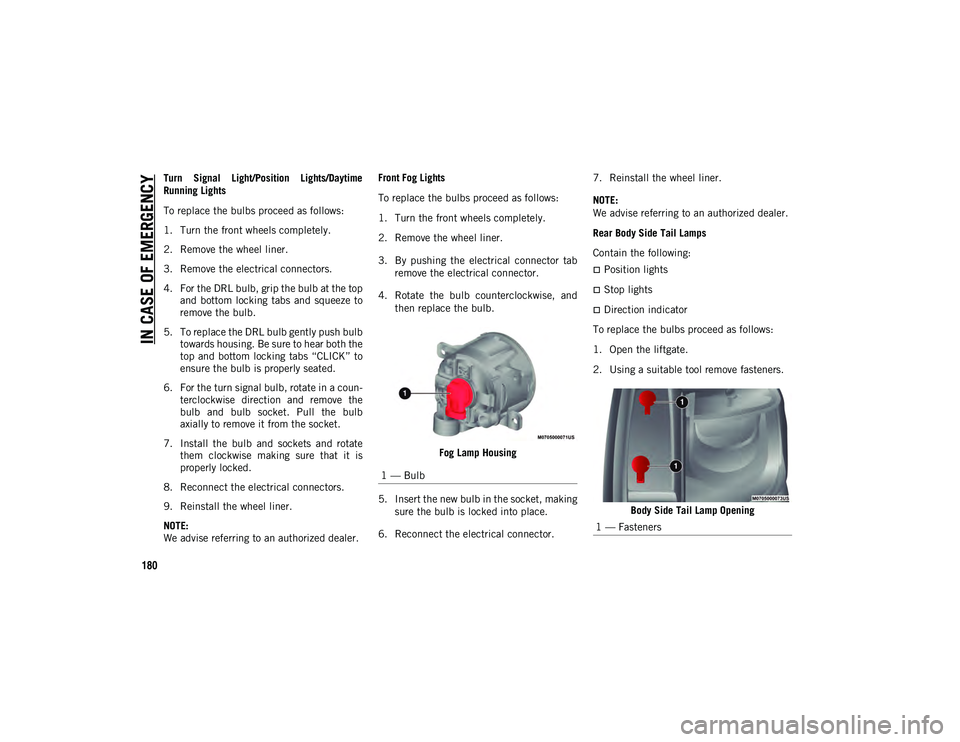
4. Rotate the bulb counterclockwise, and then replace the bulb.
Fog Lamp Housing
5. Insert the new bulb in the socket, making sure the bulb is locked into place.
6. Reconnect the electrical connector. 7. Reinstall the wheel liner.
NOTE:
We advise referring to an authorized dealer.
Rear Body Side Tail Lamps
Contain the following:
Position lights
Stop lights
Direction indicator
To replace the bulbs proceed as follows:
1. Open the liftgate.
2. Using a suitable tool remove fasteners.
Body Side Tail Lamp Opening
1 — Bulb
1 — Fasteners
2020_JEEP_M6_UG_UK.book Page 180
Page 191 of 328
189
JACKING AND TIRE
CHANGING Jack Location/Spare Tire Stowage
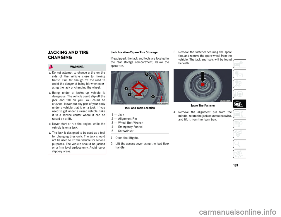
If equipped, the jack and tools are located in
the rear storage compartment, below the
spare tire.Jack And Tools Location
1. Open the liftgate.
2. Lift the access cover using the load floor handle. 3. Remove the fastener securing the spare
tire, and remove the spare wheel from the
vehicle. The jack and tools will be found
beneath.
Spare Tire Fastener
4. Remove the alignment pin from the middle, rotate the jack counterclockwise,
and lift it from the foam tray.
WARNING!
Do not attempt to change a tire on the
side of the vehicle close to moving
traffic. Pull far enough off the road to
avoid the danger of being hit when oper -
ating the jack or changing the wheel.
Being under a jacked-up vehicle is
dangerous. The vehicle could slip off the
jack and fall on you. You could be
crushed. Never put any part of your body
under a vehicle that is on a jack. If you
need to get under a raised vehicle, take
it to a service center where it can be
raised on a lift.
Never start or run the engine while the
vehicle is on a jack.
The jack is designed to be used as a tool
for changing tires only. The jack should
not be used to lift the vehicle for service
purposes. The vehicle should be jacked
on a firm level surface only. Avoid ice or
slippery areas.
1 — Jack
2 — Alignment Pin
3 — Wheel Bolt Wrench
4 — Emergency Funnel
5 — Screwdriver
2020_JEEP_M6_UG_UK.book Page 189
Page 193 of 328
191(Continued)
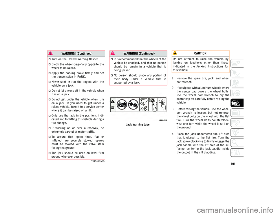
Jack Warning Label1. Remove the spare tire, jack, and wheel
bolt wrench.
2. If equipped with aluminum wheels where the center cap covers the wheel bolts,
use the wheel bolt wrench to pry the
center cap off carefully before raising the
vehicle.
3. Before raising the vehicle, use the wheel bolt wrench to loosen, but not remove,
the wheel bolts on the wheel with the flat
tire. Turn the wheel bolts counterclock -
wise one turn while the wheel is still on
the ground.
4. Place the jack underneath the lift area that is closest to the flat tire. Turn the
jack screw clockwise to firmly engage the
jack saddle with the lift area of the sill
flange, centering the jack saddle inside
the cutout in the sill cladding.
Turn on the Hazard Warning flasher.
Block the wheel diagonally opposite the
wheel to be raised.
Apply the parking brake firmly and set
the transmission in PARK.
Never start or run the engine with the
vehicle on a jack.
Do not let anyone sit in the vehicle when
it is on a jack.
Do not get under the vehicle when it is
on a jack. If you need to get under a
raised vehicle, take it to a service center
where it can be raised on a lift.
Only use the jack in the positions indi -
cated and for lifting this vehicle during a
tire change.
If working on or near a roadway, be
extremely careful of motor traffic.
To assure that spare tires, flat or
inflated, are securely stowed, spares
must be stowed with the valve stem
facing the ground.
The jack should be used on level firm
ground wherever possible.
WARNING! (Continued)
It is recommended that the wheels of the
vehicle be chocked, and that no person
should be remain in a vehicle that is
being jacked.
No person should place any portion of
their body under a vehicle that is
supported by a jack.
WARNING! (Continued) CAUTION!
Do not attempt to raise the vehicle by
jacking on locations other than those
indicated in the Jacking Instructions for
this vehicle.
2020_JEEP_M6_UG_UK.book Page 191