reset JEEP COMPASS 2020 Owner handbook (in English)
[x] Cancel search | Manufacturer: JEEP, Model Year: 2020, Model line: COMPASS, Model: JEEP COMPASS 2020Pages: 328, PDF Size: 8.85 MB
Page 27 of 328
25
NOTE:
Prior to folding the rear seat, it may be
necessary to position the front seat to its
mid-track position. Also, be sure that the
front seats are fully upright and positioned
forward. This will allow the rear seat to fold
down easily.
To Lower The Rear Seat
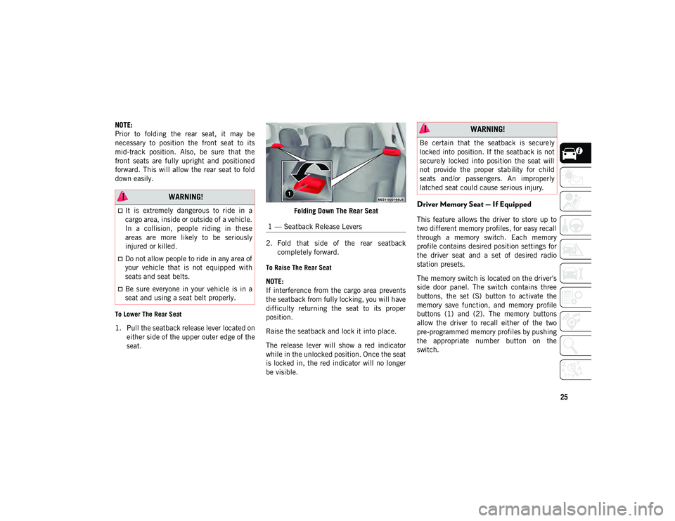
1. Pull the seatback release lever located oneither side of the upper outer edge of the
seat. Folding Down The Rear Seat
2. Fold that side of the rear seatback completely forward.
To Raise The Rear Seat
NOTE:
If interference from the cargo area prevents
the seatback from fully locking, you will have
difficulty returning the seat to its proper
position.
Raise the seatback and lock it into place.
The release lever will show a red indicator
while in the unlocked position. Once the seat
is locked in, the red indicator will no longer
be visible.
Driver Memory Seat — If Equipped
This feature allows the driver to store up to
two different memory profiles, for easy recall
through a memory switch. Each memory
profile contains desired position settings for
the driver seat and a set of desired radio
station presets.
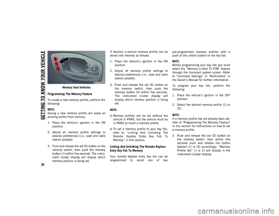
The memory switch is located on the driver's
side door panel. The switch contains three
buttons, the set (S) button to activate the
memory save function, and memory profile
buttons (1) and (2). The memory buttons
allow the driver to recall either of the two
pre-programmed memory profiles by pushing
the appropriate number button on the
switch.
WARNING!
It is extremely dangerous to ride in a
cargo area, inside or outside of a vehicle.
In a collision, people riding in these
areas are more likely to be seriously
injured or killed.
Do not allow people to ride in any area of
your vehicle that is not equipped with
seats and seat belts.
Be sure everyone in your vehicle is in a
seat and using a seat belt properly.
1 — Seatback Release Levers
WARNING!
Be certain that the seatback is securely
locked into position. If the seatback is not
securely locked into position the seat will
not provide the proper stability for child
seats and/or passengers. An improperly
latched seat could cause serious injury.
2020_JEEP_M6_UG_UK.book Page 25
Page 28 of 328
GETTING TO KNOW YOUR VEHICLE
26
Memory Seat Switches
Programming The Memory Feature
To create a new memory profile, perform the
following:
NOTE:
Saving a new memory profile will erase an
existing profile from memory.
1. Place the vehicle’s ignition in the ONposition.
2. Adjust all memory profile settings to desired preferences (i.e., seat and radio
station presets).
3. Push and release the set (S) button on the memory switch, then push the memory
button (1) within five seconds. The instru -
ment cluster display will display which
memory position is being set.
If desired, a second memory profile can be
stored into memory as follows:
1. Place the vehicle’s ignition in the ON
position.
2. Adjust all memory profile settings to desired preferences (i.e., seat and radio
station presets).
3. Push and release the set (S) button on the memory switch, then push the
memory button (2) within five seconds.
The instrument cluster display will
display which memory position is being
set.
NOTE:
Memory profiles can be set without the
vehicle in PARK, but the vehicle must be
in PARK to recall a memory profile.
To set a memory profile to your key fob,
refer to “Linking And Unlinking The
Remote Keyless Entry Key Fob To
Memory” in this section.
Linking And Unlinking The Remote Keyless
Entry Key Fob To Memory
Your remote keyless entry key fob can be
programmed to recall one of two pre-programmed memory profiles with a
push of the unlock button on the key fob.
NOTE:
Before programming your key fob you must
select the “Memory Linked To FOB” feature
through the Uconnect system screen. Refer
to “Uconnect Settings” in “Multimedia” in
the Owner’s Manual for further information.
To program your key fob, perform the
following:
1. Place the vehicle’s ignition in the OFF
position.
2. Select the desired memory profile (1) or (2).
NOTE:
If a memory profile has not already been set,
refer to "Programming The Memory Feature"
in this section for instructions on how to set
a memory profile.
3. Push and release the set (S) button on the memory switch, then within five
seconds push and release the button
labeled (1) or (2) accordingly. “Memory
Profile Set” (1 or 2) will display in the
instrument cluster display.
2020_JEEP_M6_UG_UK.book Page 26
Page 53 of 328
51
(Continued)
NOTE:
Before closing the liftgate, make sure to
be in possession of the key because the
liftgate may be locked.
Use the interior door lock/unlock button
on the door panel or the key fob to lock
and unlock the liftgate. The manual door
locks on the doors and the exterior door
lock cylinder will not lock and unlock the
liftgate.
Lock The Vehicle
NOTE:
The liftgate will not power open or close if
the gear selector is in gear or the vehicle
speed is above 0 mph (0 km/h).
If anything obstructs the power liftgate
while it is closing or opening, the liftgate
will automatically reverse to the closed or
open position, provided it meets sufficient
resistance.
There are pinch sensors attached to the
side of the liftgate opening. Light pressure
anywhere along these strips will cause the
liftgate to return to the open position.
If the power liftgate encounters multiple
obstructions within the same cycle, the
system will automatically stop. If this
occurs, the liftgate must be opened or
closed manually.
The power liftgate will not operate in
temperatures below −22°F (−30°C) or
temperatures above 150°F (65°C). Be
sure to remove any buildup of snow or ice
from the liftgate before pushing any of the
power liftgate switches.
If the liftgate is left open for an extended
period of time, the liftgate may need to be
closed manually to reset power liftgate
functionality.
Gas props support the liftgate in the open
position. However, because the gas pres-
sure drops with temperature, it may be
necessary to assist the props when
opening the liftgate in cold weather.
Before driving off, check the instrument
cluster for a liftgate or door open message
or warning indicator. Failure to do this
could result in unintentionally leaving the
liftgate open while driving.
If your liftgate is power closing and you
put the vehicle in gear, the liftgate will
continue to power close. However, vehicle
movement may result in a detection of an
obstruction.
If the electronic liftgate release handle is
pushed while the power liftgate is
opening, the liftgate motor will disengage
to allow manual operation.
If the electronic liftgate release handle is
pushed while the power liftgate is closing,
the liftgate will reverse to the full open
position.
WARNING!
During power operation, personal injury or
cargo damage may occur. Ensure the
liftgate travel path is clear. Make sure the
liftgate is closed and latched before
driving away.
WARNING!
Driving with the liftgate open can allow
poisonous exhaust gases into your
vehicle. You and your passengers could
be injured by these fumes. Keep the lift -
gate closed when you are operating the
vehicle.
2020_JEEP_M6_UG_UK.book Page 51
Page 55 of 328
53
(Continued)
NOTE:
The rear cargo area power outlet can be
switched from “ignition” only to constant
“battery” powered all the time. See an
authorized dealer for details.
Power Inverter — If Equipped
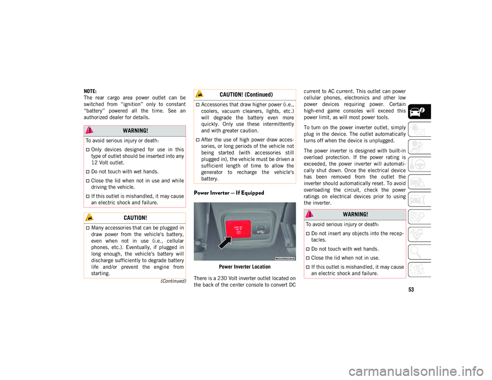
Power Inverter Location
There is a 230 Volt inverter outlet located on
the back of the center console to convert DC current to AC current. This outlet can power
cellular phones, electronics and other low
power devices requiring power. Certain
high-end game consoles will exceed this
power limit, as will most power tools.
To turn on the power inverter outlet, simply
plug in the device. The outlet automatically
turns off when the device is unplugged.
The power inverter is designed with built-in
overload protection. If the power rating is
exceeded, the power inverter will automati
-
cally shut down. Once the electrical device
has been removed from the outlet the
inverter should automatically reset. To avoid
overloading the circuit, check the power
ratings on electrical devices prior to using
the inverter.
WARNING!
To avoid serious injury or death:
Only devices designed for use in this
type of outlet should be inserted into any
12 Volt outlet.
Do not touch with wet hands.
Close the lid when not in use and while
driving the vehicle.
If this outlet is mishandled, it may cause
an electric shock and failure.
CAUTION!
Many accessories that can be plugged in
draw power from the vehicle's battery,
even when not in use (i.e., cellular
phones, etc.). Eventually, if plugged in
long enough, the vehicle's battery will
discharge sufficiently to degrade battery
life and/or prevent the engine from
starting.
Accessories that draw higher power (i.e.,
coolers, vacuum cleaners, lights, etc.)
will degrade the battery even more
quickly. Only use these intermittently
and with greater caution.
After the use of high power draw acces-
sories, or long periods of the vehicle not
being started (with accessories still
plugged in), the vehicle must be driven a
sufficient length of time to allow the
generator to recharge the vehicle's
battery.
CAUTION! (Continued)
WARNING!
To avoid serious injury or death:
Do not insert any objects into the recep -
tacles.
Do not touch with wet hands.
Close the lid when not in use.
If this outlet is mishandled, it may cause
an electric shock and failure.
2020_JEEP_M6_UG_UK.book Page 53
Page 58 of 328
GETTING TO KNOW YOUR INSTRUMENT PANEL
56
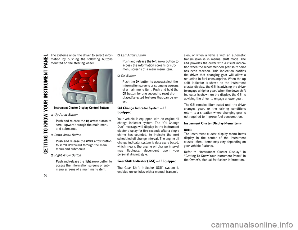
The systems allow the driver to select infor-
mation by pushing the following buttons
mounted on the steering wheel:
Instrument Cluster Display Control Buttons
Up Arrow Button Push and release the up arrow button to
scroll upward through the main menu
and submenus.
Down Arrow Button
Push and release the down arrow button
to scroll downward through the main
menu and submenus.
Right Arrow Button
Push and release the right arrow button to
access the information screens or sub -
menu screens of a main menu item.
Left Arrow Button
Push and release the left arrow button to
access the information screens or sub -
menu screens of a main menu item.
OK Button
Push the OK button to access/select the
information screens or submenu screens
of a main menu item. Push and hold the
OK button for one second to reset dis -
played/selected features that can be re -
set.
Oil Change Indicator System — If
Equipped
Your vehicle is equipped with an engine oil
change indicator system. The “Oil Change
Due” message will display in the instrument
cluster display for five seconds after a single
chime has sounded, to indicate the next
scheduled oil change interval. The engine oil
change indicator system is duty cycle based,
which means the engine oil change interval
may fluctuate, dependent upon your
personal driving style.
Gear Shift Indicator (GSI) — If Equipped
The Gear Shift Indicator (GSI) system is
enabled on vehicles with a manual transmis -sion, or when a vehicle with an automatic
transmission is in manual shift mode. The
GSI provides the driver with a visual indica
-
tion when the recommended gear shift point
has been reached. This indication notifies
the driver that changing gear will allow a
reduction in fuel consumption. When the up
shift indicator is shown on the instrument
cluster display, the GSI is advising the driver
to engage a higher gear. When the down shift
indicator is shown on the display, the GSI is
advising the driver to engage a lower gear.
The GSI remains illuminated until the driver
changes gear, or the driving conditions
return to a situation where changing gear is
not required to improve fuel consumption.
Instrument Cluster Display Menu Items
NOTE:
The instrument cluster display menu items
display in the center of the instrument
cluster. Menu items may vary depending on
your vehicle features.
Refer to “Instrument Cluster Display” in
“Getting To Know Your Instrument Panel” in
the Owner’s Manual for further information.
2020_JEEP_M6_UG_UK.book Page 56
Page 86 of 328
SAFETY
84
time, both the visual and audible alerts will
be issued. In addition to the audible alert the
radio (if on) will also be muted.
NOTE:
Whenever an audible alert is requested by
the BSM system, the radio is also muted.
When the system is in RCP, the system shall
respond with both visual and audible alerts
when a detected object is present. Whenever
an audible alert is requested, the radio
volume is reduced. Turn/hazard signal status
is ignored; the RCP state always requests the
chime.
Blind Spot Alert Off
When the BSM system is turned off there will
be no visual or audible alerts from either the
BSM or RCP systems.
NOTE:
The BSM system will store the current oper-
ating mode when the vehicle is shut off.
Each time the vehicle is started the previ -
ously stored mode will be recalled and used.
Blocked Sensor
If the system detects degraded performance
due to contamination or foreign objects, a
message will warn you of a blocked sensor and the warning indicators in side view
mirrors will be illuminated. The warning indi
-
cators will remain illuminated until blockage
clearing conditions are met. First clear the
fascia area around the sensors of the
blockage. After removing the blockage, reset
the system by placing the ignition from ON to
OFF and then back ON.
Forward Collision Warning (FCW) With
Mitigation — If Equipped
Forward Collision Warning (FCW) With
Mitigation Operation
The Forward Collision Warning (FCW) system
with mitigation provides the driver with
audible warnings, visual warnings (within the
instrument cluster display), and may apply a
brake jerk to warn the driver when it detects
a potential frontal collision. The warnings
and limited braking are intended to provide
the driver with enough time to react, avoid or
mitigate the potential collision.
NOTE:
FCW monitors the information from the
forward looking sensors as well as the Elec -
tronic Brake Controller (EBC), to calculate
the probability of a forward collision. When
the system determines that a forward colli -sion is probable, the driver will be provided
with audible and visual warnings and may
provide a brake jerk warning.
If the driver does not take action based upon
these progressive warnings, then the system
will provide a limited level of active braking
to help slow the vehicle and mitigate the
potential forward collision. If the driver
reacts to the warnings by braking and the
system determines that the driver intends to
avoid the collision by braking but has not
applied sufficient brake force, the system
will compensate and provide additional
brake force as required.
If a Forward Collision Warning with Mitiga
-
tion event begins at a speed below 26 mph
(42 km/h), the system may provide the
maximum braking possible to mitigate the
potential forward collision. If the Forward
Collision Warning with Mitigation event stops
the vehicle completely, the system will hold
the vehicle at standstill for two seconds and
then release the brakes.
2020_JEEP_M6_UG_UK.book Page 84
Page 87 of 328
85
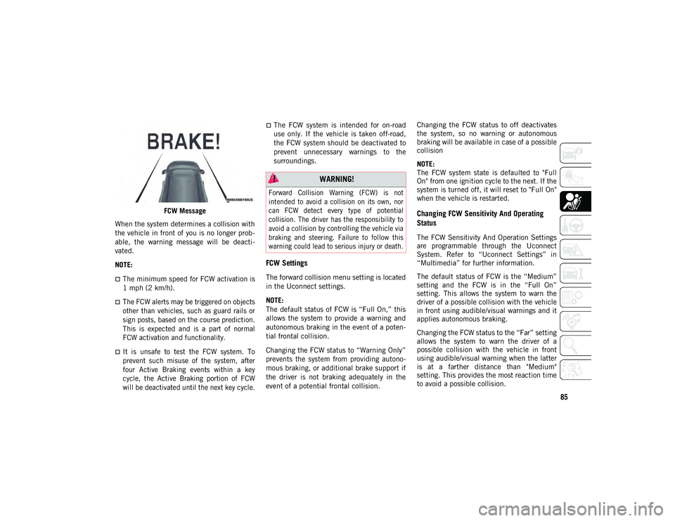
FCW Message
When the system determines a collision with
the vehicle in front of you is no longer prob -
able, the warning message will be deacti -
vated.
NOTE:
The minimum speed for FCW activation is
1 mph (2 km/h).
The FCW alerts may be triggered on objects
other than vehicles, such as guard rails or
sign posts, based on the course prediction.
This is expected and is a part of normal
FCW activation and functionality.
It is unsafe to test the FCW system. To
prevent such misuse of the system, after
four Active Braking events within a key
cycle, the Active Braking portion of FCW
will be deactivated until the next key cycle.
The FCW system is intended for on-road
use only. If the vehicle is taken off-road,
the FCW system should be deactivated to
prevent unnecessary warnings to the
surroundings.
FCW Settings
The forward collision menu setting is located
in the Uconnect settings.
NOTE:
The default status of FCW is “Full On,” this
allows the system to provide a warning and
autonomous braking in the event of a poten -
tial frontal collision.
Changing the FCW status to “Warning Only”
prevents the system from providing autono -
mous braking, or additional brake support if
the driver is not braking adequately in the
event of a potential frontal collision. Changing the FCW status to off deactivates
the system, so no warning or autonomous
braking will be available in case of a possible
collision
NOTE:
The FCW system state is defaulted to "Full
On" from one ignition cycle to the next. If the
system is turned off, it will reset to "Full On"
when the vehicle is restarted.
Changing FCW Sensitivity And Operating
Status
The FCW Sensitivity And Operation Settings
are programmable through the Uconnect
System. Refer to “Uconnect Settings” in
“Multimedia” for further information.
The default status of FCW is the “Medium”
setting and the FCW is in the “Full On”
setting. This allows the system to warn the
driver of a possible collision with the vehicle
in front using audible/visual warnings and it
applies autonomous braking.
Changing the FCW status to the “Far” setting
allows the system to warn the driver of a
possible collision with the vehicle in front
using audible/visual warning when the latter
is at a farther distance than "Medium"
setting. This provides the most reaction time
to avoid a possible collision.
WARNING!
Forward Collision Warning (FCW) is not
intended to avoid a collision on its own, nor
can FCW detect every type of potential
collision. The driver has the responsibility to
avoid a collision by controlling the vehicle via
braking and steering. Failure to follow this
warning could lead to serious injury or death.
2020_JEEP_M6_UG_UK.book Page 85
Page 88 of 328
SAFETY
86
Changing the FCW status to the “Near”
setting, allows the system to warn the driver
of a possible collision with the vehicle in
front when the distance between the vehicle
in the front is much closer. This setting
provides less reaction time than the “Far”
and “Medium” settings, which allows for a
more dynamic driving experience.
NOTE:
The system will NOT retain the last setting
selected by the driver after ignition shut
down. The system will reset to Medium
sensitivity with FCW "Full On" setting
when the vehicle is restarted.
FCW may not react to irrelevant objects
such as overhead objects, ground reflec-
tions, objects not in the path of the
vehicle, stationary objects that are far
away, oncoming traffic, or leading vehicles
with the same or higher rate of speed.
If FCW is disabled, unavailable screens
will be displayed.
FCW Limited Warning
If the instrument cluster display reads “ACC/
FCW Limited Functionality” or “ACC/FCW
Limited Functionality Clean Front Wind-
shield” momentarily, there may be a condi -tion that limits FCW functionality. Although
the vehicle is still drivable under normal
conditions, the active braking may not be
fully available. Once the condition that
limited the system performance is no longer
present, the system will return to its full
performance state. If the problem persists,
see an authorized dealer.
Service FCW Warning
If the system turns off, and the instrument
cluster display reads “FCW Unavailable
Service Required”, this indicates there is an
internal system fault. Although the vehicle is
still drivable under normal conditions, have
the system checked by an authorized dealer.
Tire Pressure Monitoring System (TPMS)
The Tire Pressure Monitoring System (TPMS)
will warn the driver of a low tire pressure
based on the vehicle recommended cold
placard pressure.
The tire pressure will vary with temperature
by approximately 1 psi (7 kPa) for every 12°F
(6.5°C). This means that when the outside
temperature decreases, the tire pressure will
decrease. Tire pressure should always be set
based on cold inflation tire pressure. This is
defined as the tire pressure after the vehicle
has not been driven for at least three hours,
or driven less than 1 mile (1.6 km) after a
three hour period. The cold tire inflation
pressure must not exceed the maximum
inflation pressure molded into the tire side
-
wall. Refer to “Tires” in “Servicing And
Maintenance” for information on how to
properly inflate the vehicle’s tires. The tire
pressure will also increase as the vehicle is
driven. This is normal and there should be no
adjustment for this increased pressure.
The TPMS will warn the driver of a low tire
pressure if the tire pressure falls below the
low-pressure warning limit for any reason,
including low temperature effects and
natural pressure loss through the tire. The
TPMS will continue to warn the driver of low
tire pressure as long as the condition exists,
and will not turn off until the tire pressure is
at or above the recommended cold placard
pressure.
NOTE:
Once the low tire pressure warning (TPMS
Warning Light) illuminates, you must
increase the tire pressure to the recom -
mended cold placard pressure in order for
the TPMS Warning Light to turn off.
2020_JEEP_M6_UG_UK.book Page 86
Page 113 of 328
111
NOTE:
Air bag covers may not be obvious in the
interior trim, but they will open during air
bag deployment.
After any collision, the vehicle should be
taken to an authorized dealer immedi-
ately.
Enhanced Accident Response System
In the event of an impact, if the communica -
tion network remains intact, and the power
remains intact, depending on the nature of
the event, the ORC will determine whether to
have the Enhanced Accident Response
System perform the following functions:
Cut off fuel to the engine (If Equipped)
Cut off battery power to the electric motor
(If Equipped)
Flash hazard lights as long as the battery
has power
Turn on the interior lights, which remain
on as long as the battery has power or for
15 minutes from the intervention of the
Enhanced Accident Response System.
Unlock the power door locks. Your vehicle may also be designed to perform
any of these other functions in response to
the Enhanced Accident Response System:
Turn off the Fuel Filter Heater, turn off the
HVAC Blower Motor, close the HVAC
Circulation Door
Cut off battery power to the:
Engine
Electric motor (if equipped)
Electric power steering
Brake booster
Electric park brake
Automatic transmission gear selector
Horn
Front wiper
Headlamp washer pump
NOTE:
After an accident, remember to place the
ignition to the STOP (OFF/LOCK) position
and remove the key from the ignition switch
to avoid draining the battery. Carefully check
the vehicle for fuel leaks in the engine
compartment and on the ground near the
engine compartment and fuel tank before resetting the system and starting the engine.
If there are no fuel leaks or damage to the
vehicle electrical devices (e.g. headlights)
after an accident, reset the system by
following the procedure described below. If
you have any doubt, contact an authorized
dealer.
Enhanced Accident Response System Reset
Procedure
After the event occurs, when the system is
active, a message regarding fuel cutoff is
displayed. Turn the ignition switch from igni
-
tion AVV/START or MAR/ACC/ON/RUN to
ignition STOP/OFF/LOCK. Carefully check
the vehicle for fuel leaks in the engine
compartment and on the ground near the
engine compartment and fuel tank before
resetting the system and starting the engine.
Depending on the nature of the event the left
and right turn signal lights, located in the
instrument panel, may both be blinking and
will continue to blink. In order to move your
vehicle to the side of the road, you must
follow the system reset procedure.
2020_JEEP_M6_UG_UK.book Page 111
Page 115 of 328
113(Continued)
If a reset procedure step is not completed
within 60 seconds, then the turn signal
lights will blink and the reset procedure must
be performed again in order to be successful.
Maintaining Your Air Bag System Event Data Recorder (EDR)
This vehicle is equipped with an Event Data
Recorder (EDR). The main purpose of an
EDR is to record, in certain crash or near
crash-like situations, such as an air bag
deployment or hitting a road obstacle, data
that will assist in understanding how a
vehicle’s systems performed. The EDR is
designed to record data related to vehicle
dynamics and safety systems for a short
period of time, typically 30 seconds or less.
The EDR in this vehicle is designed to record
such data as:
How various systems in your vehicle were
operating;
Whether or not the driver and passenger
safety belts were buckled/fastened;
11. Turn ignition STOP/OFF/LOCK.
12. Turn ignition MAR/ACC/ON/RUN. (Entire sequence needs to be
completed within one minute or sequence will need to be repeated).
System is now reset and the engine may be started.
Turn hazard flashers OFF (Manually).
Customer Action Customer Will SeeNOTE:
Each step MUST BE held for at least two seconds
WARNING!
Modifications to any part of the air bag
system could cause it to fail when you
need it. You could be injured if the air
bag system is not there to protect you.
Do not modify the components or wiring,
including adding any kind of badges or
stickers to the steering wheel hub trim
cover or the upper passenger side of the
instrument panel. Do not modify the
front bumper, vehicle body structure, or
add aftermarket side steps or running
boards.
It is dangerous to try to repair any part of
the air bag system yourself. Be sure to
tell anyone who works on your vehicle
that it has an air bag system.
Do not attempt to modify any part of your
air bag system. The air bag may inflate
accidentally or may not function properly if
modifications are made. Take your vehicle
to an authorized dealer for any air bag
system service. If your seat, including your
trim cover and cushion, needs to be
serviced in any way (including removal or
loosening/tightening of seat attachment
bolts), take the vehicle to an authorized
dealer. Only manufacturer approved seat
accessories may be used. If it is necessary
to modify the air bag system for persons
with disabilities, contact an authorized
dealer.
WARNING! (Continued)
2020_JEEP_M6_UG_UK.book Page 113