tire type JEEP COMPASS 2023 Owners Manual
[x] Cancel search | Manufacturer: JEEP, Model Year: 2023, Model line: COMPASS, Model: JEEP COMPASS 2023Pages: 344, PDF Size: 18.8 MB
Page 8 of 344
6
IN CASE OF EMERGENCY
HAZARD WARNING FLASHERS ........................ 244
SOS MIRROR — IF EQUIPPED ............................ 244
JACKING AND TIRE CHANGING —
IF EQUIPPED ......................................................... 247
Preparations For Jacking ............................. 248
Jack Location/Spare Tire Stowage .............. 248
Jacking Instructions ..................................... 250
TIRE SERVICE KIT — IF EQUIPPED ..................... 252
JUMP STARTING................................................... 258
Preparations For Jump Start......................... 258Jump Starting Procedure .............................. 259
REFUELING IN EMERGENCY............................... 260
IF YOUR ENGINE OVERHEATS ........................... 261
GEAR SELECTOR OVERRIDE ............................. 262
FREEING A STUCK VEHICLE .............................. 262
TOWING A DISABLED VEHICLE .......................... 264 Without The Key Fob ..................................... 265
Front-Wheel Drive (FWD) Models —
With Key Fob.................................................. 265
4x4 Models .................................................... 265
Emergency Tow Hooks —
If Equipped .................................................... 266 ENHANCED ACCIDENT RESPONSE
SYSTEM (EARS) .................................................. 266
EVENT DATA RECORDER (EDR) ........................ 266
SERVICING AND MAINTENANCE
SCHEDULED SERVICING ................................... 267
Maintenance Plan ......................................... 268
ENGINE COMPARTMENT .................................... 271
2.4L Engine ................................................... 271
Checking Oil Level ......................................... 272
Adding Washer Fluid .................................... 272
Maintenance-Free Battery ............................ 272
Pressure Washing ......................................... 273
VEHICLE MAINTENANCE..................................... 273
Engine Oil ....................................................... 273
Engine Oil Filter ............................................. 274Engine Air Cleaner Filter ............................... 274
Air Conditioner Maintenance........................ 274
Body Lubrication ........................................... 275Wiper Blades ................................................ 275Exhaust System ............................................ 278
Cooling System .............................................. 279
Brake System ............................................... 282
Automatic Transmission —
If Equipped..................................................... 283Fuses.............................................................. 284
Bulb Replacement ........................................ 291 TIRES .................................................................... 298
Tire Safety Information ................................ 298Tires — General Information ........................ 306Tire Types....................................................... 309Spare Tires — If Equipped ............................ 310
Snow Traction Devices ................................. 311
Tire Rotation Recommendations ................ 313
DEPARTMENT OF TRANSPORTATION UNIFORM
TIRE QUALITY GRADES ...................................... 314
Treadwear...................................................... 314
Traction Grades ............................................. 314Temperature Grades..................................... 314
STORING THE VEHICLE ....................................... 315
BODYWORK .......................................................... 315
Protection From Atmospheric Agents .......... 315
Body And Underbody Maintenance ............. 315
Preserving The Bodywork ............................. 316
INTERIORS ........................................................... 317
Seats And Fabric Parts ................................. 317
Plastic And Coated Parts .............................. 318
Leather Surfaces........................................... 318
Glass Surfaces ............................................. 318
22_MP_OM_EN_USC_t.book Page 6
Page 11 of 344
9
SYMBOLS KEY
If you do not read this entire Owner’s Manual, you may miss important
information. Observe all Cautions and Warnings.
ROLLOVER WARNING
Utility vehicles have a significantly higher rollover rate than other types of
vehicles. This vehicle has a higher ground clearance and a higher center of gravity than many passenger vehicles. It is capable of performing better in a
wide variety of off-road applications. Driven in an unsafe manner, all vehicles
can go out of control. Because of the higher center of gravity, if this vehicle is
out of control it may roll over while some other vehicles may not.
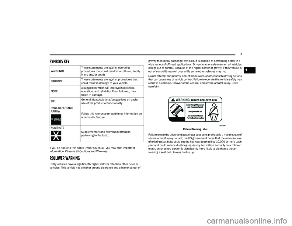
Do not attempt sharp turns, abrupt maneuvers, or other unsafe driving actions
that can cause loss of vehicle control. Failure to operate this vehicle safely may
result in a collision, rollover of the vehicle, and severe or fatal injury. Drive
carefully.
Rollover Warning Label
Failure to use the driver and passenger seat belts provided is a major cause of
severe or fatal injury. In fact, the US government notes that the universal use
of existing seat belts could cut the highway death toll by 10,000 or more each
year and could reduce disabling injuries by two million annually. In a rollover
crash, an unbelted person is significantly more likely to die than a person
wearing a seat belt. Always buckle up.
WARNING!
These statements are against operating
procedures that could result in a collision, bodily
injury and/or death.
CAUTION! These statements are against procedures that
could result in damage to your vehicle.
NOTE: A suggestion which will improve installation,
operation, and reliability. If not followed, may
result in damage.
TIP: General ideas/solutions/suggestions on easier
use of the product or functionality.
PAGE REFERENCE
ARROW Follow this reference for additional information on
a particular feature.
FOOTNOTE Supplementary and relevant information
pertaining to the topic.
1
22_MP_OM_EN_USC_t.book Page 9
Page 82 of 344
80GETTING TO KNOW YOUR INSTRUMENT PANEL
The instrument cluster display will normally display
the main menu or the screens of a selected feature
of the main menu. The main display area also
displays pop-up messages that consist of
approximately 60 possible warning or information
messages. These pop-up messages fall into
several categories:
Five Second Stored Messages
When the appropriate conditions occur, this
type of message takes control of the main
display area for five seconds and then returns to
the previous screen. Most of the messages of
this type are then stored (as long as the condi-
tion that activated it remains active) and can be
reviewed from the “Messages” main menu item.
Examples of this message type are “Right Front
Turn Signal Lamp Out” and “Low Tire Pressure.”
Unstored Messages
This message type is displayed indefinitely or
until the condition that activated the message is
cleared. Examples of this message type are
“Turn Signal On” (if a turn signal is left on) and
“Lights On” (if driver leaves the vehicle with the
lights on).
Unstored Messages Until RUN
These messages deal primarily with the Remote
Start feature. This message type is displayed
until the ignition is in the RUN state. Examples of
this message type are “Remote Start Canceled -
Door Ajar” and “Press Brake Pedal and Push
Button to Start.”
Five Second Unstored Messages
When the appropriate conditions occur, this
type of message takes control of the main
display area for five seconds and then returns to
the previous screen. An example of this
message type is “Automatic High Beams On.”
OIL CHANGE RESET
Your vehicle is equipped with an engine oil
change indicator system. The “Oil Change Due”
message will display in the instrument cluster
display for five seconds after a single chime has
sounded, to indicate the next scheduled oil
change interval. The engine oil change indicator
system is duty cycle based, which means the
engine oil change interval may fluctuate, depen -
dent upon your personal driving style.
Unless reset, this message will continue to
display each time the ignition is cycled to the
ON/RUN position.
To reset the oil change indicator after performing
the scheduled maintenance, refer to the following
procedure:
1. Without pressing the brake pedal, push the ENGINE START/STOP button and cycle the
ignition to the ON/RUN position (do not start
the engine).
2. Fully press the accelerator pedal, slowly, three times within ten seconds.
3. Cycle the ignition to the OFF position.
NOTE:If the indicator message illuminates when you start
the vehicle, the oil change indicator system did not
reset. If necessary, repeat this procedure.
22_MP_OM_EN_USC_t.book Page 80
Page 88 of 344
86GETTING TO KNOW YOUR INSTRUMENT PANEL
VEHICLE SETTINGS — IF EQUIPPED
Push and release the up or down arrow
button until the Vehicle Setup Menu item is
displayed in the instrument cluster display. This
menu item allows you to change the settings for
the following:
Display
Navigation Repetition
Security
Passenger Airbag
Seat Belt Reminder
Safety and Assistance
Speed Warning
Hill Start Assist
NOTE:Most vehicle settings will be moved into the radio
if a touchscreen radio is present Ú page 165.
Display
By selecting Display, the following settings can be
selected:
Language: select the language in which to
display the information/warnings.
Phone Repetition: displays information relating
to the phone mode. Units
By selecting Units, the unit of measurement to use
for displaying various values can be set. Possible
options are:
US
Metric
Custom: allows individual changes of units for
temperature, distance, consumption, and tire
pressure.
Clock And Date
By selecting Clock and Date, the time and date can
be set. Possible options are:
Set Time: adjust hours/minutes
Set Format: adjust the time format “12h”
(12 hours) or “24h” (24 hours)
Set Date: adjust day/month/year
Security
Passenger Air Bag Disable (PAD): a selection of
Passenger Air Bag Disable (ON/OFF) may be made
if a child restraint must be installed in the front
seat. Safety And Assistance
By selecting the item Safety and Assistance, the
following adjustments can be made:
ParkSense (If Equipped): a selection of the type
of information provided by ParkSense
Front ParkSense Volume (If Equipped): selec
-
tion of the volume of the beeps provided by the
front ParkSense
Rear ParkSense Volume (If Equipped): selection
of the volume of the beeps provided by the rear
ParkSense
Forward Collision Warning (FCW) (If Equipped): a
selection of operating modes of the system
Forward Collision Warning Plus
FCW Sensitivity (If Equipped): a selection of the
“readiness” of intervention of the Forward Colli -
sion Warning Plus system, based on the
distance to the obstacle
Rain Sensing Wipers (If Equipped): enabling/
disabling the automatic operation of wipers in
the event of rain
Active Lane Management Force (If Equipped):
selection of the force to be applied to the
steering wheel to put the car in the roadway
through the system of electrical drive, in case of
operation of the system Active Lane Manage -
ment
22_MP_OM_EN_USC_t.book Page 86
Page 97 of 344
GETTING TO KNOW YOUR INSTRUMENT PANEL95
Each tire, including the spare (if provided), should
be checked monthly when cold and inflated to the
inflation pressure recommended by the vehicle
manufacturer on the vehicle placard or tire
inflation pressure label. If your vehicle has tires of
a different size than the size indicated on the
vehicle placard or tire inflation pressure label, you
should determine the proper tire inflation pressure
for those tires.
As an added safety feature, your vehicle has been
equipped with a TPMS that illuminates a low tire
pressure telltale when one or more of your tires is
significantly underinflated. Accordingly, when the
low tire pressure telltale illuminates, you should
stop and check your tires as soon as possible, and
inflate them to the proper pressure. Driving on a
significantly underinflated tire causes the tire to
overheat and can lead to tire failure. Underinflation
also reduces fuel efficiency and tire tread life, and
may affect the vehicle’s handling and stopping
ability.
Please note that the TPMS is not a substitute for
proper tire maintenance, and it is the driver’s
responsibility to maintain correct tire pressure,
even if underinflation has not reached the level to
trigger illumination of the TPMS low tire pressure
telltale. Your vehicle has also been equipped with a TPMS
malfunction indicator to indicate when the system
is not operating properly. The TPMS malfunction
indicator is combined with the low tire pressure
telltale. When the system detects a malfunction,
the telltale will flash for approximately one minute
and then remain continuously illuminated. This
sequence will continue upon subsequent vehicle
start-ups as long as the malfunction exists. When
the malfunction indicator is illuminated, the
system may not be able to detect or signal low tire
pressure as intended. TPMS malfunctions may
occur for a variety of reasons, including the
installation of replacement or alternate tires or
wheels on the vehicle that prevent the TPMS from
functioning properly. Always check the TPMS
malfunction telltale after replacing one or more
tires or wheels on your vehicle to ensure that the
replacement or alternate tires and wheels allow
the TPMS to continue to function properly.
Towing Hook Breakdown Warning Light —
If Equipped
This light illuminates when there is a
failure with the tow hook. Contact an
authorized dealer for service.
CAUTION!
The TPMS has been optimized for the original
equipment tires and wheels. TPMS pressures
and warning have been established for the tire
size equipped on your vehicle. Undesirable
system operation or sensor damage may result
when using replacement equipment that is not
of the same size, type, and/or style. Aftermarket
wheels can cause sensor damage. Using
aftermarket tire sealants may cause the Tire
Pressure Monitoring System (TPMS) sensor to
become inoperable. After using an aftermarket
tire sealant it is recommended that you take
your vehicle to an authorized dealer to have your
sensor function checked.
3
22_MP_OM_EN_USC_t.book Page 95
Page 114 of 344
112STARTING AND OPERATING
5. Restart the engine.
6. Shift into the desired gear range. If the problem is no longer detected, the
transmission will return to normal operation.
NOTE:Even if the transmission can be reset, we
recommend that you visit an authorized dealer at
your earliest possible convenience. An authorized
dealer has diagnostic equipment to assess the
condition of your transmission. If the transmission
cannot be reset, authorized dealer service is
required.
TORQUE CONVERTER CLUTCH
A feature designed to improve fuel economy has
been included in the automatic transmission on
your vehicle. A clutch within the torque converter
engages automatically at calibrated speeds. This
may result in a slightly different feeling or response
during normal operation in the upper gears. When
the vehicle speed drops or during some
accelerations, the clutch automatically
disengages.
NOTE:The torque converter clutch will not engage until
the engine and/or transmission is warm (usually
after 1 to 3 miles [2 to 5 km] of driving). Because
the engine speed is higher when the torque
converter clutch is not engaged, it may seem as if the transmission is not shifting properly when the
vehicle is cold. This is normal. The torque converter
clutch will function normally once the powertrain is
sufficiently warm.
FOUR-WHEEL DRIVE OPERATION —
IF EQUIPPED
JEEP® ACTIVE DRIVE
Your vehicle may be equipped with a Power
Transfer Unit (PTU). This system is automatic
with no driver inputs or additional driving skills
required. Under normal driving conditions, the
front wheels provide most of the traction. If the
front wheels begin to lose traction, power is shifted
automatically to the rear wheels. The greater the
front wheel traction loss, the greater the power
transfer to the rear wheels.
Additionally, on dry pavement under heavy throttle
input (where one may have no wheel spin), torque
will be sent to the rear in a preemptive effort to
improve vehicle launch and performance
characteristics.
Four-Wheel Drive (4x4)
The four-wheel drive (4WD) is fully automatic in
normal driving mode.
NOTE:It is not possible to carry out the change of mode
when the vehicle exceeds the speed of 75 mph
(120 km/h).
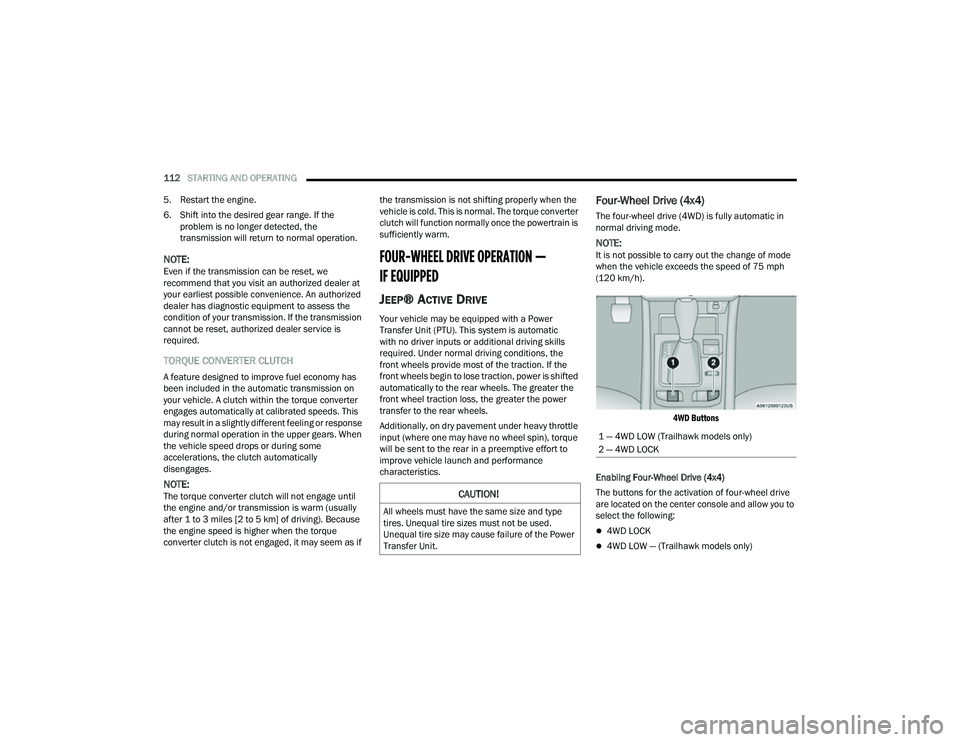
4WD Buttons
Enabling Four-Wheel Drive (4x4)
The buttons for the activation of four-wheel drive
are located on the center console and allow you to
select the following:
4WD LOCK
4WD LOW — (Trailhawk models only)
CAUTION!
All wheels must have the same size and type
tires. Unequal tire sizes must not be used.
Unequal tire size may cause failure of the Power
Transfer Unit.
1 — 4WD LOW (Trailhawk models only)
2 — 4WD LOCK
22_MP_OM_EN_USC_t.book Page 112
Page 150 of 344
148STARTING AND OPERATING
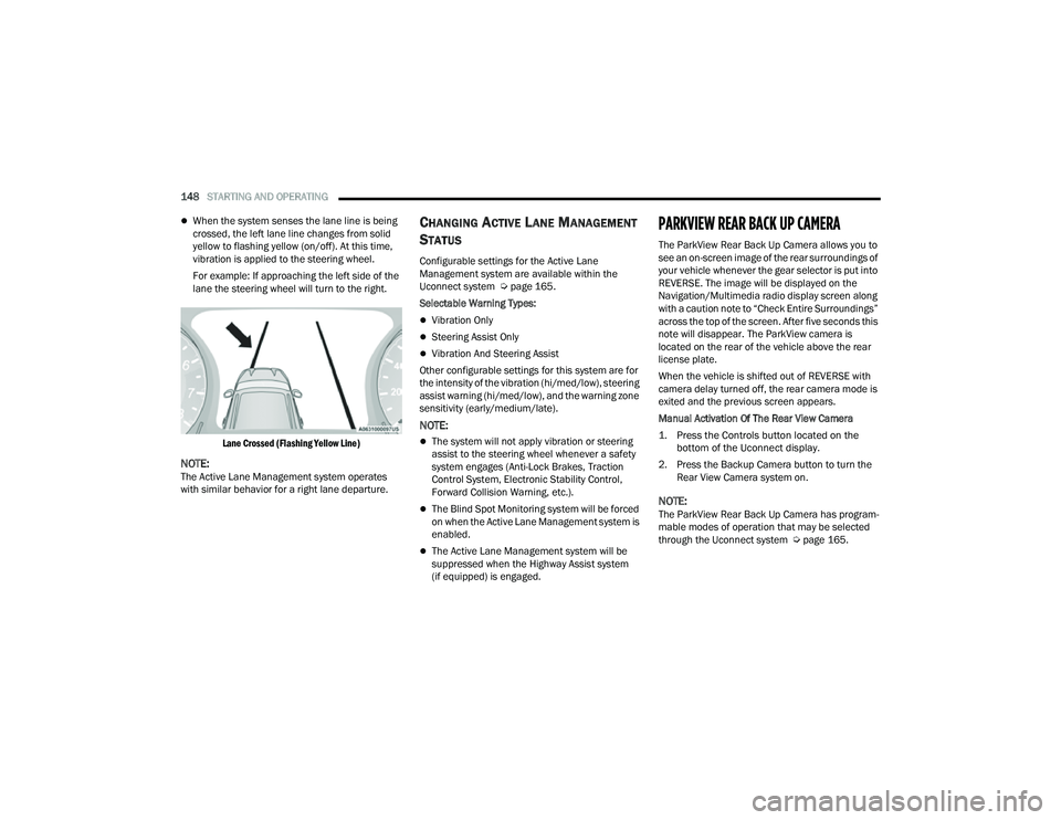
When the system senses the lane line is being
crossed, the left lane line changes from solid
yellow to flashing yellow (on/off). At this time,
vibration is applied to the steering wheel.
For example: If approaching the left side of the
lane the steering wheel will turn to the right.
Lane Crossed (Flashing Yellow Line)
NOTE:The Active Lane Management system operates
with similar behavior for a right lane departure.
CHANGING ACTIVE LANE MANAGEMENT
S
TATUS
Configurable settings for the Active Lane
Management system are available within the
Uconnect system Ú page 165.
Selectable Warning Types:
Vibration Only
Steering Assist Only
Vibration And Steering Assist
Other configurable settings for this system are for
the intensity of the vibration (hi/med/low), steering
assist warning (hi/med/low), and the warning zone
sensitivity (early/medium/late).
NOTE:
The system will not apply vibration or steering
assist to the steering wheel whenever a safety
system engages (Anti-Lock Brakes, Traction
Control System, Electronic Stability Control,
Forward Collision Warning, etc.).
The Blind Spot Monitoring system will be forced
on when the Active Lane Management system is
enabled.
The Active Lane Management system will be
suppressed when the Highway Assist system
(if equipped) is engaged.
PARKVIEW REAR BACK UP CAMERA
The ParkView Rear Back Up Camera allows you to
see an on-screen image of the rear surroundings of
your vehicle whenever the gear selector is put into
REVERSE. The image will be displayed on the
Navigation/Multimedia radio display screen along
with a caution note to “Check Entire Surroundings”
across the top of the screen. After five seconds this
note will disappear. The ParkView camera is
located on the rear of the vehicle above the rear
license plate.
When the vehicle is shifted out of REVERSE with
camera delay turned off, the rear camera mode is
exited and the previous screen appears.
Manual Activation Of The Rear View Camera
1. Press the Controls button located on the bottom of the Uconnect display.
2. Press the Backup Camera button to turn the Rear View Camera system on.
NOTE:The ParkView Rear Back Up Camera has program -
mable modes of operation that may be selected
through the Uconnect system Ú page 165.
22_MP_OM_EN_USC_t.book Page 148
Page 156 of 344
154STARTING AND OPERATING
The entire vehicle should first be weighed on a
commercial scale to ensure that the GVWR has not
been exceeded. The weight on the front and rear of
the vehicle should then be determined separately
to be sure that the load is properly distributed over
the front and rear axle. Weighing the vehicle may
show that the GAWR of either the front or rear axles
has been exceeded but the total load is within the
specified GVWR. If so, weight must be shifted from
front to rear or rear to front as appropriate until the
specified weight limitations are met. Store the
heavier items down low and be sure that the
weight is distributed equally. Stow all loose items
securely before driving.
Improper weight distributions can have an adverse
effect on the way your vehicle steers and handles
and the way the brakes operate.
TRAILER TOWING
In this section you will find safety tips and
information on limits to the type of towing you can
reasonably do with your vehicle. Before towing a
trailer, carefully review this information to tow your
load as efficiently and safely as possible.
To maintain the New Vehicle Limited Warranty
coverage, follow the requirements and
recommendations in this manual concerning
vehicles used for trailer towing.
COMMON TOWING DEFINITIONS
The following trailer towing related definitions will
assist you in understanding the following
information:
Gross Vehicle Weight Rating (GVWR)
The GVWR is the total allowable weight of your
vehicle. This includes driver, passengers, cargo
and tongue weight. The total load must be limited
so that you do not exceed the GVWR Ú page 153.
Gross Trailer Weight (GTW)
The GTW is the weight of the trailer plus the weight
of all cargo, consumables and equipment
(permanent or temporary) loaded in or on the
trailer in its "loaded and ready for operation"
condition. The recommended way to measure GTW is to put
your fully loaded trailer on a vehicle scale. The
entire weight of the trailer must be supported by
the scale.
Gross Axle Weight Rating (GAWR)
The GAWR is the maximum capacity of the front
and rear axles. Distribute the load over the front
and rear axles evenly. Make sure that you do not
exceed either front or rear GAWR Ú
page 153.
Tongue Weight (TW)
The TW is the downward force exerted on the hitch
ball by the trailer. You must consider this as part of
the load on your vehicle.
Trailer Frontal Area
The frontal area is the maximum height multiplied
by the maximum width of the front of a trailer.
CAUTION!
Do not load your vehicle any heavier than the
GVWR or the maximum front and rear GAWR. If
you do, parts on your vehicle can break, or it can
change the way your vehicle handles. This could
cause you to lose control. Overloading can
shorten the life of your vehicle.
WARNING!
It is important that you do not exceed the
maximum front or rear GAWR. A dangerous
driving condition can result if either rating is
exceeded. You could lose control of the vehicle
and have a collision.
22_MP_OM_EN_USC_t.book Page 154
Page 158 of 344
156STARTING AND OPERATING
(Continued)
TRAILER AND TONGUE WEIGHT
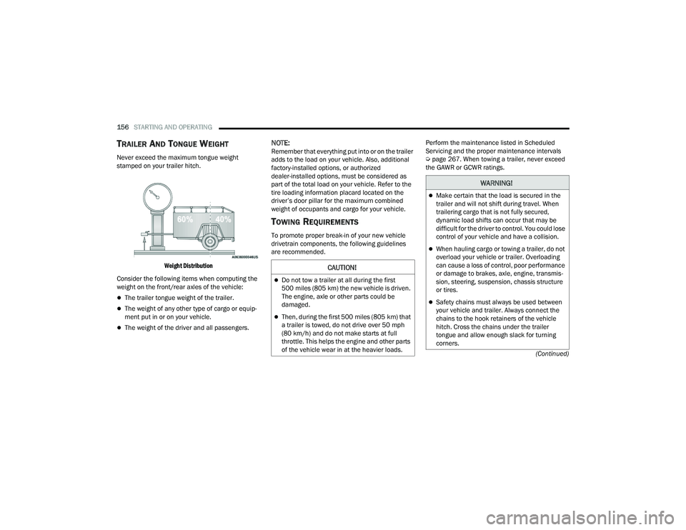
Never exceed the maximum tongue weight
stamped on your trailer hitch.
Weight Distribution
Consider the following items when computing the
weight on the front/rear axles of the vehicle:
The trailer tongue weight of the trailer.
The weight of any other type of cargo or equip -
ment put in or on your vehicle.
The weight of the driver and all passengers.
NOTE:Remember that everything put into or on the trailer
adds to the load on your vehicle. Also, additional
factory-installed options, or authorized
dealer-installed options, must be considered as
part of the total load on your vehicle. Refer to the
tire loading information placard located on the
driver’s door pillar for the maximum combined
weight of occupants and cargo for your vehicle.
TOWING REQUIREMENTS
To promote proper break-in of your new vehicle
drivetrain components, the following guidelines
are recommended. Perform the maintenance listed in Scheduled
Servicing and the proper maintenance intervals
Ú
page 267. When towing a trailer, never exceed
the GAWR or GCWR ratings.
CAUTION!
Do not tow a trailer at all during the first
500 miles (805 km) the new vehicle is driven.
The engine, axle or other parts could be
damaged.
Then, during the first 500 miles (805 km) that
a trailer is towed, do not drive over 50 mph
(80 km/h) and do not make starts at full
throttle. This helps the engine and other parts
of the vehicle wear in at the heavier loads.
WARNING!
Make certain that the load is secured in the
trailer and will not shift during travel. When
trailering cargo that is not fully secured,
dynamic load shifts can occur that may be
difficult for the driver to control. You could lose
control of your vehicle and have a collision.
When hauling cargo or towing a trailer, do not
overload your vehicle or trailer. Overloading
can cause a loss of control, poor performance
or damage to brakes, axle, engine, transmis -
sion, steering, suspension, chassis structure
or tires.
Safety chains must always be used between
your vehicle and trailer. Always connect the
chains to the hook retainers of the vehicle
hitch. Cross the chains under the trailer
tongue and allow enough slack for turning
corners.
22_MP_OM_EN_USC_t.book Page 156
Page 192 of 344
190SAFETY
(Continued)
ESC Operating Modes
Depending upon model and mode of operation, the
ESC system may have multiple operating modes.
ESC On
This is the normal operating mode for the ESC.
Whenever the vehicle is started, the ESC system
will be in this mode. This mode should be used for
most driving conditions. Alternate ESC modes
should only be used for specific reasons as noted
in the following paragraphs.Partial Off
This mode may be useful if the vehicle becomes
stuck. This mode may modify TCS and ESC
thresholds for activation, which allows for more
wheel spin than normally allowed.
To enter the “Partial Off” mode, momentarily push
the ESC OFF button, located below the radio. The
ESC OFF Indicator Light will illuminate. To turn the
ESC on again, momentarily push the ESC OFF
button and the ESC OFF Indicator Light will turn off.
NOTE:
When driving with snow chains, or when starting off
in deep snow, sand, or gravel, it may be desirable to
allow more wheel spin. This can be accomplished by
momentarily pushing the ESC OFF button to enter
“Partial Off” mode. Once the situation requiring
“Partial Off” mode is overcome, turn ESC back on by
momentarily pushing the ESC OFF button. This may
be done while the vehicle is in motion.
Full Off (Four-Wheel Drive Models Only)
This mode is intended for off-highway or off-road
use when ESC stability features could inhibit
vehicle maneuverability due to trail conditions.
This mode is entered by pushing and holding the
ESC OFF button for five seconds when the vehicle
is stopped and the engine is running. After five
seconds, the ESC OFF Indicator Light will illuminate
and the “ESC OFF” message will appear in the
instrument cluster display.
In this mode, ESC and TCS, except for the “limited
slip” feature described in the TCS section, are
turned off until the vehicle reaches a speed of
40 mph (64 km/h). At 40 mph (64 km/h), the
system returns to “Partial Off” mode, as described
above. TCS remains off. When the vehicle speed
drops below 30 mph (48 km/h), the ESC system
shuts off. ESC is deactivated at low vehicle speeds
so that it will not interfere with off-road driving.
However, ESC function returns to provide the
stability feature at speeds above 40 mph
(64 km/h). The ESC OFF Indicator Light will always
be illuminated when ESC is off.
Vehicle modifications, or failure to properly
maintain your vehicle, may change the
handling characteristics of your vehicle, and
may negatively affect the performance of the
ESC system. Changes to the steering system,
suspension, braking system, tire type and size
or wheel size may adversely affect ESC perfor
-
mance. Improperly inflated and unevenly worn
tires may also degrade ESC performance. Any
vehicle modification or poor vehicle mainte -
nance that reduces the effectiveness of the
ESC system can increase the risk of loss of
vehicle control, vehicle rollover, personal
injury and death.
WARNING!
WARNING!
When in “Partial Off” mode, the TCS function -
ality of ESC, except for the limited slip feature
described in the TCS section, has been
disabled and the ESC OFF Indicator Light will
be illuminated. When in “Partial Off” mode,
the engine power reduction feature of TCS is
disabled, and the enhanced vehicle stability
offered by the ESC system is reduced.
Trailer Sway Control (TSC) is disabled when
the ESC system is in the “Partial Off” mode.
WARNING!
22_MP_OM_EN_USC_t.book Page 190