buttons JEEP COMPASS 2023 User Guide
[x] Cancel search | Manufacturer: JEEP, Model Year: 2023, Model line: COMPASS, Model: JEEP COMPASS 2023Pages: 344, PDF Size: 18.8 MB
Page 54 of 344
52GETTING TO KNOW YOUR VEHICLE
Driver And Passenger Temperature
Control Buttons
These buttons provide the driver and passenger
with independent temperature control.
Push the red button on the faceplate or
touchscreen or press and slide the
temperature bar towards the red arrow
button on the touchscreen for warmer
temperature settings. Push the blue button on the faceplate or
touchscreen or press and slide the
temperature bar towards the blue arrow
button on the touchscreen for cooler
temperature settings.
SYNC Button
Press the SYNC button on the
touchscreen to toggle the Sync feature
on/off. The SYNC indicator is illuminated
when SYNC is on. SYNC is used to
synchronize the passenger temperature setting
with the driver temperature setting. Changing the
passenger temperature setting while in SYNC will
automatically exit this feature.
NOTE:The SYNC button is only available on the touch-
screen.
Blower Control
Blower Control is used to regulate the
amount of air forced through the Climate
Control system. There are seven blower
speeds available. Adjusting the blower
will cause automatic mode to switch to manual
operation. The speeds can be selected using either
the blower control knob on the faceplate or the
buttons on the touchscreen. Faceplate
The blower speed increases as you turn the blower
control knob clockwise from the lowest blower
setting. The blower speed decreases as you turn
the blower control knob counterclockwise.
Touchscreen
Use the small blower icon to reduce the blower
setting and the large blower icon to increase the
blower setting. Blower can also be selected by
pressing the blower bar area between the icons.
Mode Control
Mode Control regulates the airflow
distribution. The airflow distribution
outlets are: instrument panel outlets,
floor outlets, defrost outlets, and
demist outlets.
Faceplate
Push the Mode button to change the airflow
distribution mode.
Touchscreen
Press one of the “MODE” buttons to change the
airflow distribution mode.
CAUTION!
Failure to follow these cautions can cause
damage to the heating elements:
Use care when washing the inside of the rear
window. Do not use abrasive window cleaners
on the interior surface of the window. Use a
soft cloth and a mild washing solution, wiping
parallel to the heating elements. Labels can
be peeled off after soaking with warm water.
Do not use scrapers, sharp instruments, or
abrasive window cleaners on the interior
surface of the window.
Keep all objects a safe distance from the
window.
22_MP_OM_EN_USC_t.book Page 52
Page 57 of 344
GETTING TO KNOW YOUR VEHICLE55
Temperature Control
Temperature Control regulates the temperature of
the air forced through the climate system.
Push the red button on the faceplate or
touchscreen or press and slide the
temperature bar towards the red arrow
button on the touchscreen for warmer
temperature settings.
Push the blue button on the faceplate or
touchscreen or press and slide the
temperature bar towards the blue arrow
button on the touchscreen for cooler
temperature settings.
Blower Control
Blower Control is used to regulate the
amount of air forced through the Climate
Control system. There are seven blower
speeds available. Adjusting the blower
will cause automatic mode to switch to manual
operation. The speeds can be selected using either
the blower control knob on the faceplate or the
buttons on the touchscreen.
Faceplate
The blower speed increases as you turn the blower
control knob clockwise from the lowest blower
setting. The blower speed decreases as you turn
the blower control knob counterclockwise. Touchscreen
Use the small blower icon to reduce the blower
setting and the large blower icon to increase the
blower setting. Blower can also be selected by
pressing the blower bar area between the icons.
Mode Control
Push the Mode Control button to change
the airflow distribution mode. The airflow
distribution mode can be adjusted so air
comes from the instrument panel
outlets, floor outlets, defrost outlets and demist
outlets.
Panel Mode
Air comes from the outlets in the
instrument panel. Each of these outlets
can be individually adjusted to direct the
flow of air. The air vanes of the center
outlets and outboard outlets can be moved up and
down or side to side to regulate airflow direction.
There is a shut-off wheel located below the air
vanes to shut off or adjust the amount of airflow
from these outlets.
Bi-Level Mode
Air comes from the instrument panel
outlets and floor outlets. A slight amount
of air is directed through the defrost and
side window demister outlets.
NOTE:Bi-Level mode is designed under comfort condi -
tions to provide cooler air out of the panel outlets
and warmer air from the floor outlets.
Floor Mode
Air comes from the floor outlets. A slight
amount of air is directed through the
defrost and side window demister
outlets.
Defrost Mode
Air comes from the windshield and side
window demist outlets. When the defrost
button is selected, the blower level may
increase. Use Defrost mode with
maximum temperature settings for best
windshield and side window defrosting and
defogging. When toggling the front defrost mode
button, the Climate Control system will return to
the previous setting.
Mix Mode
Air is directed through the floor, defrost,
and side window demister outlets. This
setting works best in cold or snowy
conditions that require extra heat to the
windshield. This setting is good for maintaining
comfort while reducing moisture on the
windshield.
2
22_MP_OM_EN_USC_t.book Page 55
Page 58 of 344
56GETTING TO KNOW YOUR VEHICLE
Climate Control OFF
Press and release this button on the
touchscreen, or push and release the
button on the faceplate to turn the
Climate Control ON/OFF.
AUTOMATIC TEMPERATURE CONTROL
(ATC)
Automatic Operation
1. Push the AUTO button on the faceplate, or the
AUTO button on the touchscreen (if equipped)
on the Automatic Temperature Control (ATC)
Panel.
2. Next, adjust the temperature you would like the system to maintain by adjusting the
temperature control buttons. Once the desired
temperature is displayed, the system achieves
and automatically maintains that comfort level.
3. When the system is set up for your comfort level, it is not necessary to change the
settings. You experience the greatest
efficiency by simply allowing the system to
function automatically.
NOTE:
It is not necessary to move the temperature
settings for cold or hot vehicles. The system
automatically adjusts the temperature, mode,
and blower speed to provide comfort as quickly
as possible.
The temperature can be displayed in US or
Metric units by selecting the US/Metric
customer-programmable feature.
To provide you with maximum comfort in the
Automatic mode during cold start-ups, the blower
fan remains on low until the engine warms up.
The blower increases in speed and transition into
Auto mode.
Manual Operation Override
This system offers a full complement of manual
override features. The AUTO symbol in the front
ATC display will be turned off when the system is
being used in the manual mode.
CLIMATE VOICE COMMANDS
Adjust vehicle temperatures hands-free and keep
everyone comfortable while you keep moving ahead.
Push the VR button on the steering wheel. After the
beep, say one of the following commands:
“ Set the driver temperature to 70 degrees ”
“Set the passenger temperature to 70 degrees ”Did You Know:
Voice Command for Climate may
only be used to adjust the interior temperature of
your vehicle. Voice Command will not work to
adjust the heated seats or steering wheel if
equipped.
OPERATING TIPS
Refer to the chart at the end of this section for
suggested control settings for various weather
conditions.
Summer Operation
The engine cooling system must be protected with
a high-quality antifreeze coolant to provide proper
corrosion protection and to protect against engine
overheating. OAT coolant (conforming to
MS.90032) is recommended.
Winter Operation
To ensure the best possible heater and defroster
performance, make sure the engine cooling
system is functioning properly and the proper
amount, type, and concentration of coolant is
used. Use of the Air Recirculation mode during
Winter months is not recommended, because it
may cause window fogging.
Vacation/Storage
For information on maintaining the Climate Control
system when the vehicle is being stored for an
extended period of time, see Ú page 315.
22_MP_OM_EN_USC_t.book Page 56
Page 61 of 344
GETTING TO KNOW YOUR VEHICLE59
Plugging in a phone or another USB device may
cause the connection to a previous device to be
lost.
Front USB Ports
By using a USB cable to connect an external
device:
The device can be played on the vehicle’s sound
system, providing the artist, track title, and
album information on the radio display.
NOTE:Depending on track configuration, track infor -
mation may not be present on the radio display.
The device can be controlled using the radio
buttons to play, and browse the contents of the
device.
The audio device battery charges when plugged
into the USB port.
The second row USB ports can be used to charge
an external device.
Charge Only Rear USB Ports
NOTE:Charge unsupported devices with the Charge Only
USB ports. If an unsupported device is plugged into
a Media USB port, a message will display on the
touchscreen that the device is not supported by
the system.
POWER OUTLETS — IF EQUIPPED
Your vehicle may be equipped with 12 Volt
(13 Amp) power outlets that can be used to power
cellular phones, small electronics and other low
powered electrical accessories. The power outlets
are labeled with either a key or a battery symbol to
indicate how the outlet is powered. Power outlets
labeled with a key are powered when the ignition is
in the ON/RUN position, while the outlets labeled
with a battery are connected directly to the battery
and powered at all times.
NOTE:All accessories connected to the battery powered
outlets should be removed or turned off when the
vehicle is not in use to protect the battery against
discharge.
1 — Type C USB Port
2 — Type A USB Port
CAUTION!
Power outlets are designed for accessory plugs
only. Do not insert any other object in the power
outlets as this will damage the outlet and blow
the fuse. Improper use of the power outlet can
cause damage not covered by your New Vehicle
Limited Warranty.
2
22_MP_OM_EN_USC_t.book Page 59
Page 70 of 344
68GETTING TO KNOW YOUR VEHICLE
The key fob and the overhead console switch will
open the liftgate when the liftgate is locked. The
outside handle requires the liftgate to be unlocked.
If the vehicle is equipped with Passive Entry, and a
valid Passive Entry key fob is within 5 ft (1.5 m) of the liftgate, pulling the outside handle will unlock
and open the liftgate.
NOTE:
Before closing the liftgate, make sure to be in
possession of the key because the liftgate may
be locked.
Use the interior door lock/unlock button on the
door panel or the key fob to lock and unlock the
liftgate. The manual door locks on the doors and
the exterior door lock cylinder will not lock and
unlock the liftgate.
The liftgate will either unlock along with the
vehicle doors, or it will need to be unlocked by
pushing the electronic liftgate release,
depending on the selected setting in the
Uconnect system Ú page 165.
The power liftgate buttons will not operate if the
vehicle is in gear or the vehicle speed is above
0 mph (0 km/h).
The power liftgate will not operate in tempera -
tures below −22°F (−30°C) or temperatures
above 150°F (65°C). Be sure to remove any
buildup of snow or ice from the liftgate before
pushing any of the power liftgate switches.
If anything obstructs the power liftgate while it is
closing or opening, the liftgate will automatically
reverse to the closed or open position. After
multiple obstructions in the same cycle, the lift -
gate will automatically stop and must be opened
or closed manually.
There are pinch sensors attached to the side of
the liftgate. Light pressure anywhere along
these strips will cause the liftgate to return to
the open position.
The power liftgate must be in the full open posi -
tion in order for the rear liftgate close button, on
the left rear trim near the liftgate opening, to
operate. If the liftgate is not fully open, push the
liftgate button on the key fob to fully open the
liftgate and then push it again to close.
If the electronic liftgate release handle is
pushed a second time while the power liftgate is
opening, the liftgate motor will disengage to
allow manual operation.
If your liftgate is power closing and you put the
vehicle in gear, the liftgate will continue to
power close. However, vehicle movement may
result in the detection of an obstruction.
Allow the power system to open the liftgate.
Manually pushing or pulling the liftgate may acti -
vate the liftgate obstacle detection feature and
stop the power operation or reverse its direc -
tion. Lock The Vehicle
With a valid Passive Entry key fob within 5 ft
(1.5 m) of the liftgate, pushing the Passive Entry
lock button located to the right of the electronic
liftgate release handle will lock the vehicle.
WARNING!
Driving with the liftgate open can allow
poisonous exhaust gases into your vehicle.
You and your passengers could be injured by
these fumes. Keep the liftgate closed when
you are operating the vehicle.
If you are required to drive with the liftgate
open, make sure that all windows are closed,
and the climate control blower switch is set at
high speed. Do not use the recirculation
mode.
During power operation, personal injury or
cargo damage may occur. Ensure the liftgate
travel path is clear. Make sure the liftgate is
closed and latched before driving away.
Personal injury or cargo damage may occur if
caught in the path of the liftgate. Make sure
the liftgate path is clear before activating the
liftgate.
22_MP_OM_EN_USC_t.book Page 68
Page 80 of 344
78GETTING TO KNOW YOUR INSTRUMENT PANEL
INSTRUMENT CLUSTER DISPLAY
L
OCATION AND CONTROLS
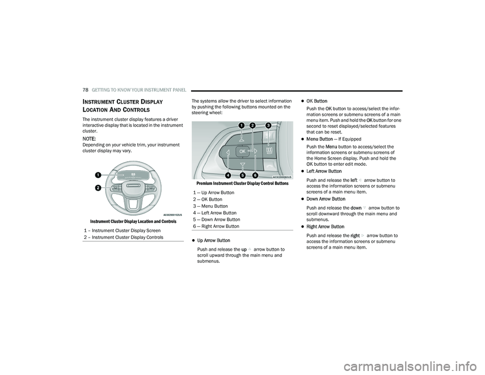
The instrument cluster display features a driver
interactive display that is located in the instrument
cluster.
NOTE:Depending on your vehicle trim, your instrument
cluster display may vary.
Instrument Cluster Display Location and Controls
The systems allow the driver to select information
by pushing the following buttons mounted on the
steering wheel:
Premium Instrument Cluster Display Control Buttons
Up Arrow Button
Push and release the up arrow button to
scroll upward through the main menu and
submenus.
OK Button
Push the OK button to access/select the infor -
mation screens or submenu screens of a main
menu item. Push and hold the OK button for one
second to reset displayed/selected features
that can be reset.
Menu Button — If Equipped
Push the Menu button to access/select the
information screens or submenu screens of
the Home Screen display. Push and hold the
OK button to enter edit mode.
Left Arrow Button
Push and release the left arrow button to
access the information screens or submenu
screens of a main menu item.
Down Arrow Button
Push and release the down arrow button to
scroll downward through the main menu and
submenus.
Right Arrow Button
Push and release the right arrow button to
access the information screens or submenu
screens of a main menu item.
1 – Instrument Cluster Display Screen
2 – Instrument Cluster Display Controls
1 — Up Arrow Button
2 — OK Button
3 — Menu Button
4 — Left Arrow Button
5 — Down Arrow Button
6 — Right Arrow Button
22_MP_OM_EN_USC_t.book Page 78
Page 84 of 344
82GETTING TO KNOW YOUR INSTRUMENT PANEL
INSTRUMENT CLUSTER DISPLAY MENU
I
TEMS
The instrument cluster display can be used to view
the main menu items for several features. Use the
up and down arrow buttons to scroll through
the driver interactive display menu options until
the desired menu is reached.
NOTE:The instrument cluster display menu items display
in the center of the instrument cluster. Menu items
may vary depending on your vehicle features.
Home Screen — If Equipped
Press the Menu button to display the Home
Screen.
Push and release the left or right arrow
button to highlight the desired selection. Push and
release the OK button to select. Press the up or
down arrow button to select a different screen
within the selected category. If the Menu button is
pressed in this view, the instrument cluster will
return to the previously displayed screen. Home Screen Options
Navigation — If Equipped
Route Set
Trip
• Trip A
• Trip B
Vehicle Info
Coolant Temp
Trans Temp
Oil Temp
Oil Pressure — If Equipped
Battery Voltage
DEF — If Equipped
Tire Pressure
Fuel Economy
Driver Info
Posted Speed Limit Sign
Driver Assist
Audio
Audio Info
Off Road — If Equipped
Selec-Terrain Status
Stored Messages
Messages
Settings
Screen Setup
Speed Warning
Screen Setup
Stop/Start
DRIVER INFO— IF EQUIPPED
Speedometer
Push and release the
up or down arrow button
until the Speedometer Menu item is displayed in the
instrument cluster display. Push and release the
OK button to change the speedometer scale from
MPH to km/h (or vice versa).
Driver Assist
Push and release the up or down arrow
button until the Driver Assist menu icon is
displayed in the instrument cluster display. Push
and release the OK button to select. The Driver
Assist screen indicates the current status of ACC,
Active Lane Management and Highway Assist/
Assist+/Pilot. Push and release the OK button to
again to change between Zoomed In and Zoomed
Out view (“Press OK to Zoom In” will display when
in Zoomed Out view/“Press OK to Zoom Out” will
display when in Zoomed In view).
22_MP_OM_EN_USC_t.book Page 82
Page 114 of 344
112STARTING AND OPERATING
5. Restart the engine.
6. Shift into the desired gear range. If the problem is no longer detected, the
transmission will return to normal operation.
NOTE:Even if the transmission can be reset, we
recommend that you visit an authorized dealer at
your earliest possible convenience. An authorized
dealer has diagnostic equipment to assess the
condition of your transmission. If the transmission
cannot be reset, authorized dealer service is
required.
TORQUE CONVERTER CLUTCH
A feature designed to improve fuel economy has
been included in the automatic transmission on
your vehicle. A clutch within the torque converter
engages automatically at calibrated speeds. This
may result in a slightly different feeling or response
during normal operation in the upper gears. When
the vehicle speed drops or during some
accelerations, the clutch automatically
disengages.
NOTE:The torque converter clutch will not engage until
the engine and/or transmission is warm (usually
after 1 to 3 miles [2 to 5 km] of driving). Because
the engine speed is higher when the torque
converter clutch is not engaged, it may seem as if the transmission is not shifting properly when the
vehicle is cold. This is normal. The torque converter
clutch will function normally once the powertrain is
sufficiently warm.
FOUR-WHEEL DRIVE OPERATION —
IF EQUIPPED
JEEP® ACTIVE DRIVE
Your vehicle may be equipped with a Power
Transfer Unit (PTU). This system is automatic
with no driver inputs or additional driving skills
required. Under normal driving conditions, the
front wheels provide most of the traction. If the
front wheels begin to lose traction, power is shifted
automatically to the rear wheels. The greater the
front wheel traction loss, the greater the power
transfer to the rear wheels.
Additionally, on dry pavement under heavy throttle
input (where one may have no wheel spin), torque
will be sent to the rear in a preemptive effort to
improve vehicle launch and performance
characteristics.
Four-Wheel Drive (4x4)
The four-wheel drive (4WD) is fully automatic in
normal driving mode.
NOTE:It is not possible to carry out the change of mode
when the vehicle exceeds the speed of 75 mph
(120 km/h).
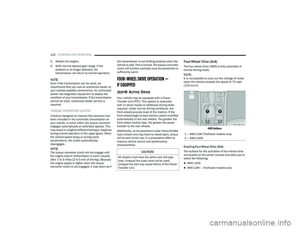
4WD Buttons
Enabling Four-Wheel Drive (4x4)
The buttons for the activation of four-wheel drive
are located on the center console and allow you to
select the following:
4WD LOCK
4WD LOW — (Trailhawk models only)
CAUTION!
All wheels must have the same size and type
tires. Unequal tire sizes must not be used.
Unequal tire size may cause failure of the Power
Transfer Unit.
1 — 4WD LOW (Trailhawk models only)
2 — 4WD LOCK
22_MP_OM_EN_USC_t.book Page 112
Page 115 of 344
STARTING AND OPERATING113
Active Drive Control — If Equipped
The Power Transfer Unit (PTU) is locked to ensure
immediate availability of torque to the rear drive
axles. This feature is selectable in AUTO mode and
automatic in the other driving mode. 4WD LOCK
can be enabled by the following ways:
When the 4WD LOCK button is pushed.
When the Selec-Terrain switch is moved from
AUTO to any other off-road modes.
Active Drive With Low Control — (Trailhawk models
only)
The 4WD LOW mode helps to improve the off-road
performance in all modes. To enable 4WD LOW,
please follow the steps below:
Enabling 4WD LOW
With the vehicle stationary, the ignition in the ON/
RUN position or with the engine running, shift the
transmission into NEUTRAL and push the 4WD
LOW button once. The instrument cluster will
display the message “4WD LOW” once the shift is
complete.
NOTE:
Both LOCK and LOW LED lights will blink and
then become active on the buttons until the
shift is complete.
The instrument cluster display will illuminate the
4WD LOW icon. Disabling 4WD LOW
To disable the 4WD LOW mode, the vehicle must
be stationary and the transmission shifted into
NEUTRAL. Push the 4WD LOW button once.
SELEC-TERRAIN — IF EQUIPPED
Selec-Terrain combines the capabilities of the
vehicle control systems, along with driver input, to
provide the best performance for all terrains.
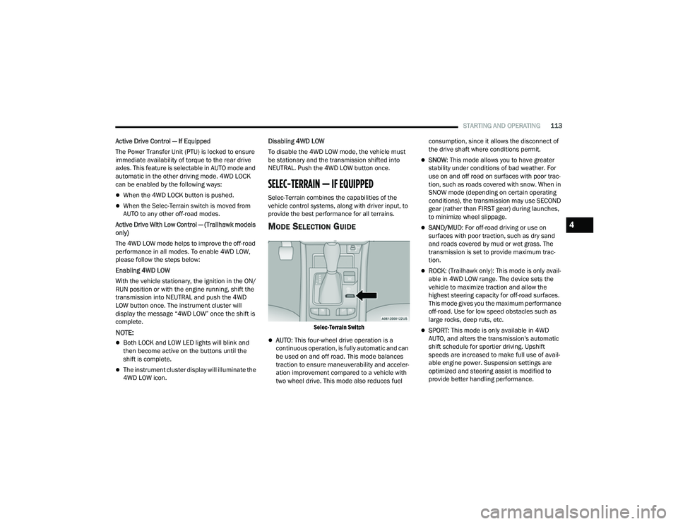
MODE SELECTION GUIDE
Selec-Terrain Switch
AUTO
: This four-wheel drive operation is a
continuous operation, is fully automatic and can
be used on and off road. This mode balances
traction to ensure maneuverability and acceler -
ation improvement compared to a vehicle with
two wheel drive. This mode also reduces fuel consumption, since it allows the disconnect of
the drive shaft where conditions permit.
SNOW
: This mode allows you to have greater
stability under conditions of bad weather. For
use on and off road on surfaces with poor trac-
tion, such as roads covered with snow. When in
SNOW mode (depending on certain operating
conditions), the transmission may use SECOND
gear (rather than FIRST gear) during launches,
to minimize wheel slippage.
SAND/MUD : For off-road driving or use on
surfaces with poor traction, such as dry sand
and roads covered by mud or wet grass. The
transmission is set to provide maximum trac -
tion.
ROCK : (Trailhawk only): This mode is only avail -
able in 4WD LOW range. The device sets the
vehicle to maximize traction and allow the
highest steering capacity for off-road surfaces.
This mode gives you the maximum performance
off-road. Use for low speed obstacles such as
large rocks, deep ruts, etc.
SPORT : This mode is only available in 4WD
AUTO, and alters the transmission's automatic
shift schedule for sportier driving. Upshift
speeds are increased to make full use of avail -
able engine power. Suspension settings are
optimized and steering assist is modified to
provide better handling performance.
4
22_MP_OM_EN_USC_t.book Page 113
Page 119 of 344
STARTING AND OPERATING117
CRUISE CONTROL
When engaged, the Cruise Control takes over
accelerator operations at speeds greater than
20 mph (32 km/h).
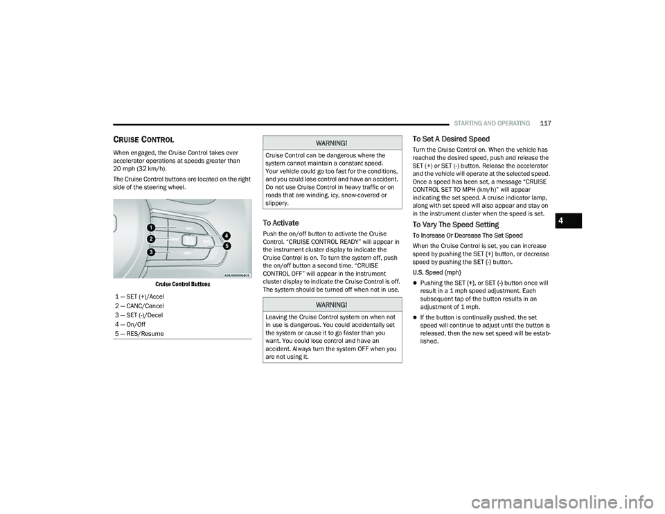
The Cruise Control buttons are located on the right
side of the steering wheel.
Cruise Control Buttons
To Activate
Push the on/off button to activate the Cruise
Control. “CRUISE CONTROL READY” will appear in
the instrument cluster display to indicate the
Cruise Control is on. To turn the system off, push
the on/off button a second time. “CRUISE
CONTROL OFF” will appear in the instrument
cluster display to indicate the Cruise Control is off.
The system should be turned off when not in use.
To Set A Desired Speed
Turn the Cruise Control on. When the vehicle has
reached the desired speed, push and release the
SET (+) or SET (-) button. Release the accelerator
and the vehicle will operate at the selected speed.
Once a speed has been set, a message “CRUISE
CONTROL SET TO MPH (km/h)” will appear
indicating the set speed. A cruise indicator lamp,
along with set speed will also appear and stay on
in the instrument cluster when the speed is set.
To Vary The Speed Setting
To Increase Or Decrease The Set Speed
When the Cruise Control is set, you can increase
speed by pushing the SET (+) button, or decrease
speed by pushing the SET (-) button.
U.S. Speed (mph)
Pushing the SET (+) , or SET (-) button once will
result in a 1 mph speed adjustment. Each
subsequent tap of the button results in an
adjustment of 1 mph.
If the button is continually pushed, the set
speed will continue to adjust until the button is
released, then the new set speed will be estab -
lished.
1 — SET (+)/Accel
2 — CANC/Cancel
3 — SET (-)/Decel
4 — On/Off
5 — RES/Resume
WARNING!
Cruise Control can be dangerous where the
system cannot maintain a constant speed.
Your vehicle could go too fast for the conditions,
and you could lose control and have an accident.
Do not use Cruise Control in heavy traffic or on
roads that are winding, icy, snow-covered or
slippery.
WARNING!
Leaving the Cruise Control system on when not
in use is dangerous. You could accidentally set
the system or cause it to go faster than you
want. You could lose control and have an
accident. Always turn the system OFF when you
are not using it.
4
22_MP_OM_EN_USC_t.book Page 117