key JEEP COMPASS 2023 Owner's Manual
[x] Cancel search | Manufacturer: JEEP, Model Year: 2023, Model line: COMPASS, Model: JEEP COMPASS 2023Pages: 344, PDF Size: 18.8 MB
Page 64 of 344
62GETTING TO KNOW YOUR VEHICLE
WINDOWS
POWER WINDOW CONTROLS
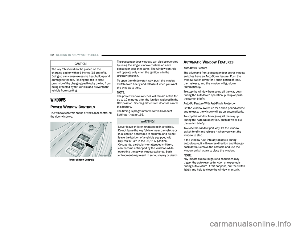
The window controls on the driver's door control all
the door windows.
Power Window Controls
The passenger door windows can also be operated
by using the single window controls on each
passenger door trim panel. The window controls
will operate only when the ignition is in the
ON/RUN position.
To open the window part way, push the window
switch down briefly and release it when you want
the window to stop.
NOTE:The power window switches will remain active for
up to 10 minutes after the ignition is placed in the
OFF position. Opening either front door will cancel
this feature.
The timing is programmable within Uconnect
Settings Ú
page 165.
AUTOMATIC WINDOW FEATURES
Auto-Down Feature
The driver and front passenger door power window
switches have an Auto-Down feature. Push the
window switch down for a short period of time,
then release, and the window will go down
automatically.
To stop the window from going all the way down
during the Auto-Down operation, pull up or push
the switch briefly.
Auto-Up Feature With Anti-Pinch Protection
Lift the window switch up for a short period of time
and release; the window will go up automatically.
To stop the window from going all the way up
during the Auto-Up operation, push down or pull
the switch briefly.
To close the window part way, lift the window
switch briefly and release it when you want the
window to stop.
If the window runs into any obstacle during
auto-closure, it will reverse direction and then go
back down. Remove the obstacle and use the
window switch again to close the window.
NOTE:Any impact due to rough road conditions may
trigger the auto-reverse function unexpectedly
during auto-closure. If this happens, pull the switch
lightly and hold to close the window manually.
CAUTION!
The key fob should not be placed on the
charging pad or within 6 inches (15 cm) of it.
Doing so can cause excessive heat buildup and
damage to the fob. Placing the fob in close
proximity of the charging pad blocks the fob from
being detected by the vehicle and prevents the
vehicle from starting.
WARNING!
Never leave children unattended in a vehicle.
Do not leave the key fob in or near the vehicle or
in a location accessible to children, and do not
leave the ignition of a vehicle equipped with
Keyless ‘n Go™ in the ON/RUN position.
Occupants, particularly unattended children,
can become entrapped by the windows while
operating the power window switches. Such
entrapment may result in serious injury or death.
22_MP_OM_EN_USC_t.book Page 62
Page 66 of 344
64GETTING TO KNOW YOUR VEHICLE
OPENING AND CLOSING THE SUNROOF
The sunroof has two programmed open positions,
comfort stop position and full open position. The
comfort stop position has been optimized to
minimize wind buffeting when driving with side
windows closed and sunroof open. If the sunshade
is in the closed position when initiating a sunroof
open or vent command the sunshade will
automatically open to the half open position prior
to the sunroof opening.
Express Open/Close
Push the switch to open and release it within
one-half second and the sunroof will open to the
comfort stop (partially opened) position and
automatically stop. Push the switch and release it
again, and the sunroof will open to the full open
position then automatically stop.
Pull the switch to close and release it within
one-half second and the sunroof will completely
close automatically from any position.
During Express Open or Express Close operation,
any movement of the sunroof switch will stop the
sunroof. Manual Open/Close
Push and hold the switch to open. The sunroof will
open to the comfort stop (partially opened)
position and automatically stop. Push the switch
and hold it again, and the sunroof will open to the
full open position then automatically stop.
Pull and hold the switch to completely close the
sunroof from any position.
Any release of the switch during open or close
operation will stop the sunroof movement. The
sunroof will remain in a partially opened position
until the switch is operated and held again.
VENTING SUNROOF
Push and release the vent switch within one-half
second and the sunroof will move from the closed
position to the vent position. This is called “Express
Vent.” During Express Vent operation, any
movement of the switch will stop the sunroof.
NOTE:When the sunroof is in a full open or a partial open
position, Express Vent operation is not available.
You must push and hold the vent switch to cycle
the sunroof from a slide open position to the vent
position. Sunroof movement will stop if the switch
is released prior to the sunroof reaching the vent
position.
WARNING!
Never leave children unattended in a vehicle,
or with access to an unlocked vehicle. Never
leave the key fob in or near the vehicle, or in a
location accessible to children. Do not leave
the ignition of a vehicle equipped with Keyless
Enter ‘n Go™ in the ON/RUN position. Occu
-
pants, particularly unattended children, can
become entrapped by the power sunroof while
operating the power sunroof switch. Such
entrapment may result in serious injury or
death.
In a collision, there is a greater risk of being
thrown from a vehicle with an open sunroof.
You could also be seriously injured or killed.
Always fasten your seat belt properly and
make sure all passengers are also properly
secured.
Do not allow small children to operate the
sunroof. Never allow your fingers, other body
parts, or any object, to project through the
sunroof opening. Injury may result.
Do not use the sunroof and its related parts
for supporting and/or grabbing purposes.
Serious personal injury may result to fingers
and other body parts as well as damage to the
sunroof.
22_MP_OM_EN_USC_t.book Page 64
Page 68 of 344
66GETTING TO KNOW YOUR VEHICLE
HOOD
OPENING THE HOOD
Two latches must be released to open the hood.
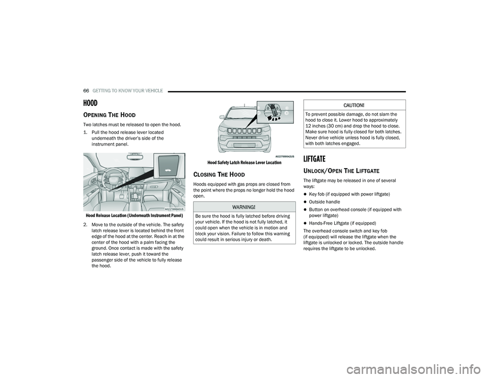
1. Pull the hood release lever located
underneath the driver’s side of the
instrument panel.
Hood Release Location (Underneath Instrument Panel)
2. Move to the outside of the vehicle. The safety latch release lever is located behind the front
edge of the hood at the center. Reach in at the
center of the hood with a palm facing the
ground. Once contact is made with the safety
latch release lever, push it toward the
passenger side of the vehicle to fully release
the hood.
Hood Safety Latch Release Lever Location
CLOSING THE HOOD
Hoods equipped with gas props are closed from
the point where the props no longer hold the hood
open.
LIFTGATE
UNLOCK/OPEN THE LIFTGATE
The liftgate may be released in one of several
ways:
Key fob (if equipped with power liftgate)
Outside handle
Button on overhead console (if equipped with
power liftgate)
Hands-Free Liftgate (if equipped)
The overhead console switch and key fob
(if equipped) will release the liftgate when the
liftgate is unlocked or locked. The outside handle
requires the liftgate to be unlocked.
WARNING!
Be sure the hood is fully latched before driving
your vehicle. If the hood is not fully latched, it
could open when the vehicle is in motion and
block your vision. Failure to follow this warning
could result in serious injury or death.
CAUTION!
To prevent possible damage, do not slam the
hood to close it. Lower hood to approximately
12 inches (30 cm) and drop the hood to close.
Make sure hood is fully closed for both latches.
Never drive vehicle unless hood is fully closed,
with both latches engaged.
22_MP_OM_EN_USC_t.book Page 66
Page 69 of 344
GETTING TO KNOW YOUR VEHICLE67
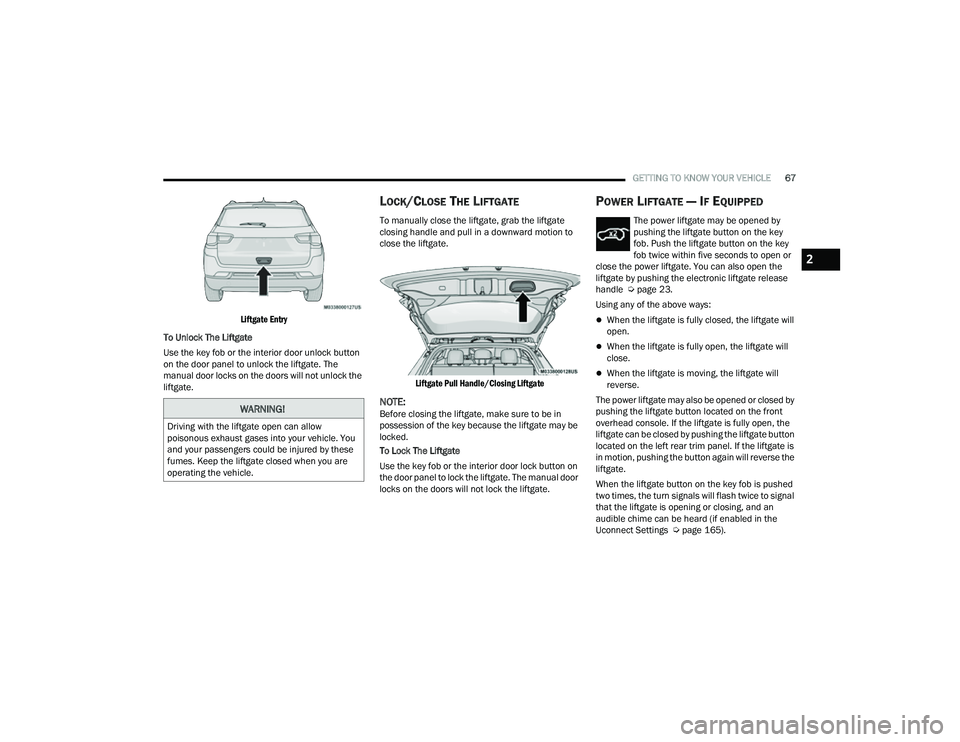
Liftgate Entry
To Unlock The Liftgate
Use the key fob or the interior door unlock button
on the door panel to unlock the liftgate. The
manual door locks on the doors will not unlock the
liftgate.
LOCK/CLOSE THE LIFTGATE
To manually close the liftgate, grab the liftgate
closing handle and pull in a downward motion to
close the liftgate.
Liftgate Pull Handle/Closing Liftgate
NOTE:Before closing the liftgate, make sure to be in
possession of the key because the liftgate may be
locked.
To Lock The Liftgate
Use the key fob or the interior door lock button on
the door panel to lock the liftgate. The manual door
locks on the doors will not lock the liftgate.
POWER LIFTGATE — IF EQUIPPED
The power liftgate may be opened by
pushing the liftgate button on the key
fob. Push the liftgate button on the key
fob twice within five seconds to open or
close the power liftgate. You can also open the
liftgate by pushing the electronic liftgate release
handle Ú page 23.
Using any of the above ways:
When the liftgate is fully closed, the liftgate will
open.
When the liftgate is fully open, the liftgate will
close.
When the liftgate is moving, the liftgate will
reverse.
The power liftgate may also be opened or closed by
pushing the liftgate button located on the front
overhead console. If the liftgate is fully open, the
liftgate can be closed by pushing the liftgate button
located on the left rear trim panel. If the liftgate is
in motion, pushing the button again will reverse the
liftgate.
When the liftgate button on the key fob is pushed
two times, the turn signals will flash twice to signal
that the liftgate is opening or closing, and an
audible chime can be heard (if enabled in the
Uconnect Settings Ú page 165).
WARNING!
Driving with the liftgate open can allow
poisonous exhaust gases into your vehicle. You
and your passengers could be injured by these
fumes. Keep the liftgate closed when you are
operating the vehicle.
2
22_MP_OM_EN_USC_t.book Page 67
Page 70 of 344
68GETTING TO KNOW YOUR VEHICLE
The key fob and the overhead console switch will
open the liftgate when the liftgate is locked. The
outside handle requires the liftgate to be unlocked.
If the vehicle is equipped with Passive Entry, and a
valid Passive Entry key fob is within 5 ft (1.5 m) of the liftgate, pulling the outside handle will unlock
and open the liftgate.
NOTE:
Before closing the liftgate, make sure to be in
possession of the key because the liftgate may
be locked.
Use the interior door lock/unlock button on the
door panel or the key fob to lock and unlock the
liftgate. The manual door locks on the doors and
the exterior door lock cylinder will not lock and
unlock the liftgate.
The liftgate will either unlock along with the
vehicle doors, or it will need to be unlocked by
pushing the electronic liftgate release,
depending on the selected setting in the
Uconnect system Ú page 165.
The power liftgate buttons will not operate if the
vehicle is in gear or the vehicle speed is above
0 mph (0 km/h).
The power liftgate will not operate in tempera -
tures below −22°F (−30°C) or temperatures
above 150°F (65°C). Be sure to remove any
buildup of snow or ice from the liftgate before
pushing any of the power liftgate switches.
If anything obstructs the power liftgate while it is
closing or opening, the liftgate will automatically
reverse to the closed or open position. After
multiple obstructions in the same cycle, the lift -
gate will automatically stop and must be opened
or closed manually.
There are pinch sensors attached to the side of
the liftgate. Light pressure anywhere along
these strips will cause the liftgate to return to
the open position.
The power liftgate must be in the full open posi -
tion in order for the rear liftgate close button, on
the left rear trim near the liftgate opening, to
operate. If the liftgate is not fully open, push the
liftgate button on the key fob to fully open the
liftgate and then push it again to close.
If the electronic liftgate release handle is
pushed a second time while the power liftgate is
opening, the liftgate motor will disengage to
allow manual operation.
If your liftgate is power closing and you put the
vehicle in gear, the liftgate will continue to
power close. However, vehicle movement may
result in the detection of an obstruction.
Allow the power system to open the liftgate.
Manually pushing or pulling the liftgate may acti -
vate the liftgate obstacle detection feature and
stop the power operation or reverse its direc -
tion. Lock The Vehicle
With a valid Passive Entry key fob within 5 ft
(1.5 m) of the liftgate, pushing the Passive Entry
lock button located to the right of the electronic
liftgate release handle will lock the vehicle.
WARNING!
Driving with the liftgate open can allow
poisonous exhaust gases into your vehicle.
You and your passengers could be injured by
these fumes. Keep the liftgate closed when
you are operating the vehicle.
If you are required to drive with the liftgate
open, make sure that all windows are closed,
and the climate control blower switch is set at
high speed. Do not use the recirculation
mode.
During power operation, personal injury or
cargo damage may occur. Ensure the liftgate
travel path is clear. Make sure the liftgate is
closed and latched before driving away.
Personal injury or cargo damage may occur if
caught in the path of the liftgate. Make sure
the liftgate path is clear before activating the
liftgate.
22_MP_OM_EN_USC_t.book Page 68
Page 71 of 344
GETTING TO KNOW YOUR VEHICLE69
(Continued)
HANDS-FREE LIFTGATE — IF EQUIPPED
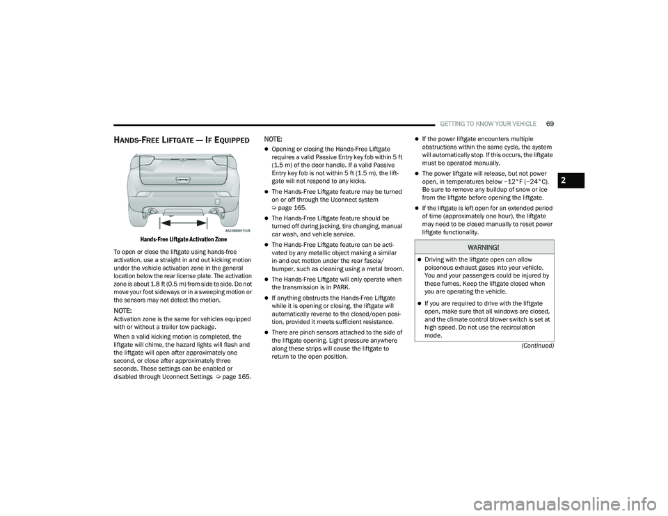
Hands-Free Liftgate Activation Zone
To open or close the liftgate using hands-free
activation, use a straight in and out kicking motion
under the vehicle activation zone in the general
location below the rear license plate. The activation
zone is about 1.8 ft (0.5 m) from side to side. Do not move your foot sideways or in a sweeping motion or
the sensors may not detect the motion.
NOTE:Activation zone is the same for vehicles equipped
with or without a trailer tow package.
When a valid kicking motion is completed, the
liftgate will chime, the hazard lights will flash and
the liftgate will open after approximately one
second, or close after approximately three
seconds. These settings can be enabled or
disabled through Uconnect Settings Ú page 165.
NOTE:
Opening or closing the Hands-Free Liftgate
requires a valid Passive Entry key fob within 5 ft
(1.5 m) of the door handle. If a valid Passive
Entry key fob is not within 5 ft (1.5 m), the lift -
gate will not respond to any kicks.
The Hands-Free Liftgate feature may be turned
on or off through the Uconnect system
Ú page 165.
The Hands-Free Liftgate feature should be
turned off during jacking, tire changing, manual
car wash, and vehicle service.
The Hands-Free Liftgate feature can be acti -
vated by any metallic object making a similar
in-and-out motion under the rear fascia/
bumper, such as cleaning using a metal broom.
The Hands-Free Liftgate will only operate when
the transmission is in PARK.
If anything obstructs the Hands-Free Liftgate
while it is opening or closing, the liftgate will
automatically reverse to the closed/open posi -
tion, provided it meets sufficient resistance.
There are pinch sensors attached to the side of
the liftgate opening. Light pressure anywhere
along these strips will cause the liftgate to
return to the open position.
If the power liftgate encounters multiple
obstructions within the same cycle, the system
will automatically stop. If this occurs, the liftgate
must be operated manually.
The power liftgate will release, but not power
open, in temperatures below −12°F (−24°C).
Be sure to remove any buildup of snow or ice
from the liftgate before opening the liftgate.
If the liftgate is left open for an extended period
of time (approximately one hour), the liftgate
may need to be closed manually to reset power
liftgate functionality.
WARNING!
Driving with the liftgate open can allow
poisonous exhaust gases into your vehicle.
You and your passengers could be injured by
these fumes. Keep the liftgate closed when
you are operating the vehicle.
If you are required to drive with the liftgate
open, make sure that all windows are closed,
and the climate control blower switch is set at
high speed. Do not use the recirculation
mode.
2
22_MP_OM_EN_USC_t.book Page 69
Page 79 of 344
GETTING TO KNOW YOUR INSTRUMENT PANEL77
PREMIUM INSTRUMENT CLUSTER
D
ESCRIPTIONS
1. Temperature Gauge
The temperature gauge shows engine
coolant temperature. Any reading within the
normal range indicates that the engine
cooling system is operating satisfactorily.
The pointer will likely indicate a higher
temperature when driving in hot weather,
up mountain grades, or when towing a
trailer. It should not be allowed to exceed
the upper limits of the normal operating
range. 2. Tachometer
Indicates the engine speed in revolutions
per minute (RPM x 1000).
3. Speedometer
Indicates vehicle speed.
4. Fuel Gauge
The pointer shows the level of fuel in the
fuel tank when the Keyless Push Button
Ignition is in the ON/RUN position.
The fuel pump symbol points to
the side of the vehicle where the
fuel door is located.
NOTE:The Instrument Cluster Warning Indicators will illu -
minate briefly for a bulb check when the ignition is
first cycled.
INSTRUMENT CLUSTER DISPLAY
Your vehicle may be equipped with an instrument
cluster display, which offers useful information to
the driver. With the ignition in the OFF mode,
opening/closing of a door will activate the display
for viewing, and display the total miles, or
kilometers, in the odometer. Your instrument
cluster display is designed to display important
information about your vehicle’s systems and
features. Using the driver interactive display
located on the instrument panel, your instrument
cluster display can show you how systems are
working and give you warnings when they aren’t.
The steering wheel mounted controls allow you to
scroll through and enter the main menus and
submenus. You can access the specific
information you want and make selections and
adjustments.
WARNING!
A hot engine cooling system is dangerous. You or
others could be badly burned by steam or boiling
coolant. It is recommended to call an authorized
dealer for service if your vehicle overheats
Ú page 279.
CAUTION!
Driving with a hot engine cooling system could
damage your vehicle. If the temperature gauge
reads “H”, pull over and stop the vehicle. Idle the
vehicle with the air conditioner turned off until
the pointer drops back into the normal range. If
the pointer remains on the “H”, turn the engine
off immediately and call an authorized dealer for
service.
3
22_MP_OM_EN_USC_t.book Page 77
Page 89 of 344
GETTING TO KNOW YOUR INSTRUMENT PANEL87
Active Lane Management Warning (If
Equipped): a selection of the “readiness” of
intervention of Active Lane Management
Buzzer Volume: There are 4 options: Off, Low,
Medium, Loud
Brake Service (If Equipped): activation of the
procedure to carry out braking system mainte-
nance
Auto Park Brake (If Equipped): enable/disable
auto insertion of the Electric Park Brake
Hill Start Assist: Activation/Deactivation of the
Hill Start Assist system
Lights — If Equipped
By selecting Lights, the following adjustments can
be made:
Ambient Lights (If Equipped): adjust the sensi -
tivity of lighting in the doors and overhead
console
Lights Off Delay: set the delay for headlight
shutoff after engine shutoff
Headlight Sensitivity: adjust the sensitivity of
headlight brightness
Greeting Lights: activate the direction indicators
when unlocking the doors
Daytime Lights (If Equipped): activate/deacti -
vate the daytime running lights
Cornering Lights (If Equipped): activate/deacti-
vate the cornering lights
Auto High Beam (If Equipped): activate/deacti -
vate the automatic high beam headlights
Doors And Locks
By selecting Doors and Locks, the following
adjustments can be made:
Auto Unlock Doors: automatic unlocking of the
doors when exiting the vehicle
Lights with Lock: activate the direction indica -
tors when locking the doors
Horn With Remote Lock: activate/deactivate the
horn when pressing the lock button on the key.
The options are “Off”, “First Press”, and
“Second Press”
Horn With Remote Start (If Equipped): activate/
deactivate the horn at the Remote Starting of
the engine with the key
Door Unlock: allow you to choose whether to
unlock all the doors or only the driver’s side door
on the first push of the unlock button on the key
Auto Driver Comfort (If Equipped): activate/
deactivate automatic climate control during
vehicle starts
Key in Memory (If Equipped): activate/deacti -
vate memory linked to a key
Compass
By selecting Compass, the following settings can
be changed:
Calibration (If Equipped)
This compass is self-calibrating, which eliminates
the need to set the compass manually. When the
vehicle is new, the compass may appear erratic,
and the cluster will display dashes (- -) until the
compass is calibrated. You may also calibrate the
compass by completing one or more 360 degree
turns (in an area free from large metal or metallic
objects) until the dashes (- -) displayed in the
instrument cluster display turns off. The compass
will now function normally.
3
22_MP_OM_EN_USC_t.book Page 87
Page 102 of 344
100 (Continued)
STARTING AND OPERATING
STARTING THE ENGINE
Before starting your vehicle, adjust your seat,
adjust both inside and outside mirrors, and fasten
your seat belts. Start the engine with the gear selector in the
NEUTRAL or PARK position. Apply the brake before
shifting to any driving range.
NORMAL STARTING
Place the ignition switch in the START position and
release when the engine starts. If the engine fails
to start within 10 seconds, place the ignition
switch in the LOCK/OFF position, wait 10 to
15 seconds, then repeat the “Normal Starting”
procedure.
Tip Start Feature
Place the ignition switch in the START position
and release it as soon as the starter engages.
The starter motor will continue to run, and will
automatically disengage itself when the engine is
running. If the engine fails to start, place the
ignition switch in the OFF position, wait 10 to
15 seconds, then repeat the “Normal Starting”
procedure.
Automatic Transmission
The gear selector must be in the NEUTRAL or PARK
position before you can start the engine. Apply the
brakes before shifting into any driving gear.
Keyless Enter ’n Go™ Functions — Using The
ENGINE START/STOP Button
1. The transmission must be in PARK or NEUTRAL.
2. Press and hold the brake pedal while pushing the ENGINE START/STOP button once.
WARNING!
When exiting the vehicle, always remove the
key fob from the vehicle and lock your vehicle.
Never leave children alone in a vehicle, or with
access to an unlocked vehicle.
Allowing children to be in a vehicle unattended
is dangerous for a number of reasons. A child
or others could be seriously or fatally injured.
Children should be warned not to touch the
parking brake, brake pedal or the transmis -
sion gear selector.
Do not leave the key fob in or near the vehicle,
or in a location accessible to children, and do
not leave the ignition of a vehicle equipped
with Keyless Enter ’n Go™ in the ON/RUN
position. A child could operate power
windows, other controls, or move the vehicle.
Do not leave children or animals inside parked
vehicles in hot weather. Interior heat build-up
may cause serious injury or death.
WARNING!
CAUTION!
Damage to the transmission may occur if the
following precautions are not observed:
Do not shift between PARK, REVERSE,
NEUTRAL, or DRIVE when the engine is
above idle speed.
Shift into or out of PARK or REVERSE only after
the vehicle has come to a complete stop.
Before shifting into any gear, make sure your
foot is firmly on the brake pedal.
22_MP_OM_EN_USC_t.book Page 100
Page 103 of 344
STARTING AND OPERATING101
3. The system starts the vehicle. If the vehicle fails to start, the starter will disengage
automatically after 10 seconds.
4. If you wish to stop the cranking of the engine prior to the engine starting, push the ENGINE
START/STOP button again.
Keyless Enter ’n Go™ — With Driver’s Foot OFF The
Brake Pedal (In PARK Or NEUTRAL Position)
The Keyless Enter ’n Go™ feature operates similar
to an ignition switch. It has three positions, OFF,
ON/RUN, and START. To change the ignition switch
positions without starting the vehicle and use the
accessories follow, these steps starting with the
ignition switch in the OFF position:
1. Push the ENGINE START/STOP button once to change the ignition switch to the ON/RUN
position.
2. Push the ENGINE START/STOP button a second time to change the ignition switch to
the OFF position.
COLD WEATHER OPERATION
(B
ELOW –22°F OR −30°C)
To ensure reliable starting at these temperatures,
use of an externally powered electric engine block
heater (available from an authorized dealer) is
recommended.
EXTENDED PARK STARTING
NOTE:Extended Park condition occurs when the vehicle
has not been started or driven for at least 30 days.
1. Install a battery charger or jumper cables to
the battery to ensure a full battery charge
during the crank cycle.
2. Place the ignition in the START position and release it when the engine starts.
3. If the engine fails to start within 10 seconds, place the ignition in the OFF position, wait
10 to 15 seconds to allow the starter to cool,
then repeat the “Extended Park Starting”
procedure.
4. If the engine fails to start after eight attempts, allow the starter to cool for at least
10 minutes, then repeat the procedure.
AFTER STARTING — WARMING UP THE
E
NGINE
The idle speed is controlled automatically and it
will decrease as the engine warms up.
IF ENGINE FAILS TO START
If the engine fails to start after you have followed
the “Normal Starting” procedure, and has not
experienced an Extended Park condition as
identified in “Extended Park Starting” procedure, it
may be flooded. Push the accelerator pedal all the
way to the floor and hold it there. Crank the engine
for no more than 15 seconds. This should clear any
excess fuel in case the engine is flooded. Leave the
ignition key in the ON/RUN position, release the
accelerator pedal and repeat the “Normal
Starting” procedure.
CAUTION!
To prevent damage to the starter, do not crank
continuously for more than 10 seconds at a
time. Wait 10 to 15 seconds before trying again.
CAUTION!
To prevent damage to the starter, do not
continuously crank the engine for more than
25 seconds at a time. Wait 60 seconds before
trying again.
4
22_MP_OM_EN_USC_t.book Page 101