key JEEP COMPASS 2023 Service Manual
[x] Cancel search | Manufacturer: JEEP, Model Year: 2023, Model line: COMPASS, Model: JEEP COMPASS 2023Pages: 344, PDF Size: 18.8 MB
Page 183 of 344
MULTIMEDIA181
Key Off Options
Audio
When the Key Off Options button is pressed on the touchscreen, the system displays the options related to vehicle shutoff. These settings will only activate
when the ignition is set to OFF.
NOTE:Depending on the vehicle’s options, feature settings may vary.
Setting Name Description
Radio Off Delay This setting will keep the radio running after the engine is turned off. When
any door is opened, the electronics will deactivate. The available settings are
“0 min” and “20 min”.
Radio Off With Door This setting will shut the radio off when the door is opened. The available
settings are “On” and “Off”.
Headlight Off Delay This setting will allow you to set the amount of time the headlights remain on
after the vehicle has been turned off. The “+” will increase the amount of
time. The “-” will decrease the amount of time.
When the Audio button is pressed on the touchscreen, the system displays options related to the vehicle’s sound system. These settings can change the audio
location within the vehicle, adjust the bass or treble levels, and auto-play settings from an audio device or smartphone.
NOTE:Depending on the vehicle’s options, feature settings may vary.
Setting Name
Description
Balance/Fade This setting will adjust audio levels from specific speakers in the front/back
and left/right of the vehicle. The Speaker icon can be moved to set audio
location.
5
22_MP_OM_EN_USC_t.book Page 181
Page 201 of 344
SAFETY199
If a Forward Collision Warning with Mitigation event
begins at a speed below 39 mph (62 km/h), the
system may provide the maximum braking
possible to mitigate the potential forward collision.
If the Forward Collision Warning with Mitigation
event stops the vehicle completely, the system will
hold the vehicle at standstill for two seconds and
then release the brakes.
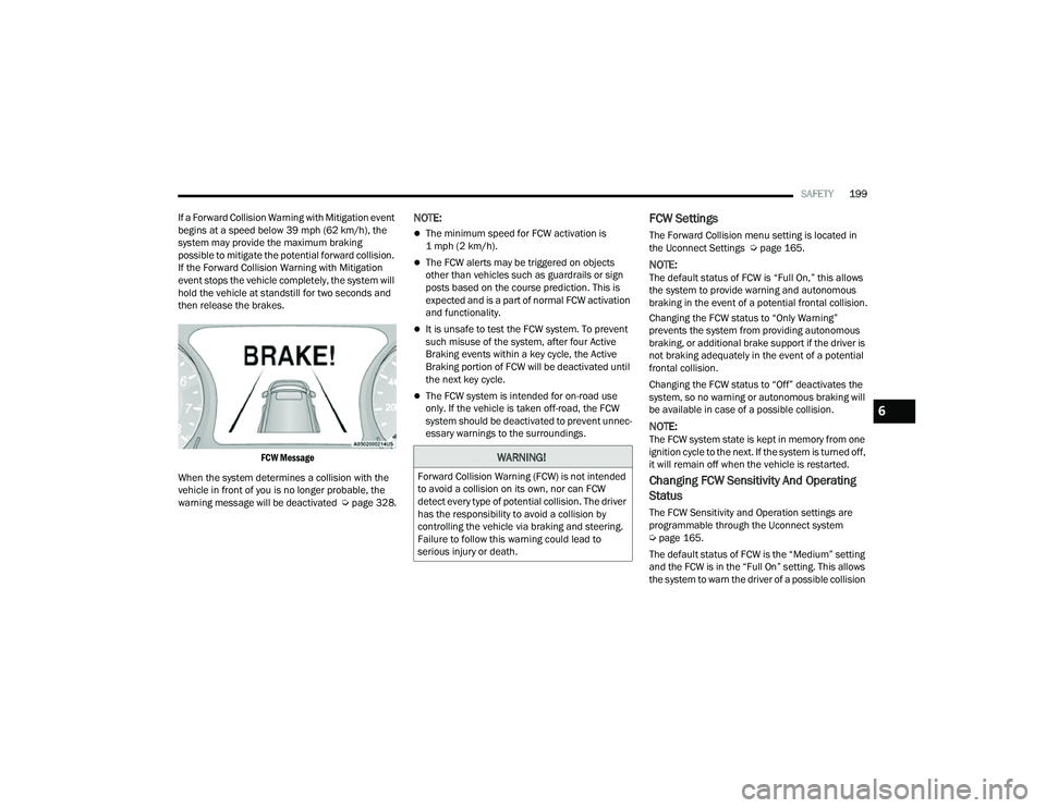
FCW Message
When the system determines a collision with the
vehicle in front of you is no longer probable, the
warning message will be deactivated Úpage 328.
NOTE:
The minimum speed for FCW activation is
1 mph (2 km/h).
The FCW alerts may be triggered on objects
other than vehicles such as guardrails or sign
posts based on the course prediction. This is
expected and is a part of normal FCW activation
and functionality.
It is unsafe to test the FCW system. To prevent
such misuse of the system, after four Active
Braking events within a key cycle, the Active
Braking portion of FCW will be deactivated until
the next key cycle.
The FCW system is intended for on-road use
only. If the vehicle is taken off-road, the FCW
system should be deactivated to prevent unnec -
essary warnings to the surroundings.
FCW Settings
The Forward Collision menu setting is located in
the Uconnect Settings Ú page 165.
NOTE:The default status of FCW is “Full On,” this allows
the system to provide warning and autonomous
braking in the event of a potential frontal collision.
Changing the FCW status to “Only Warning”
prevents the system from providing autonomous
braking, or additional brake support if the driver is
not braking adequately in the event of a potential
frontal collision.
Changing the FCW status to “Off” deactivates the
system, so no warning or autonomous braking will
be available in case of a possible collision.
NOTE:The FCW system state is kept in memory from one
ignition cycle to the next. If the system is turned off,
it will remain off when the vehicle is restarted.
Changing FCW Sensitivity And Operating
Status
The FCW Sensitivity and Operation settings are
programmable through the Uconnect system
Úpage 165.
The default status of FCW is the “Medium” setting
and the FCW is in the “Full On” setting. This allows
the system to warn the driver of a possible collision
WARNING!
Forward Collision Warning (FCW) is not intended
to avoid a collision on its own, nor can FCW
detect every type of potential collision. The driver
has the responsibility to avoid a collision by
controlling the vehicle via braking and steering.
Failure to follow this warning could lead to
serious injury or death.
6
22_MP_OM_EN_USC_t.book Page 199
Page 205 of 344
SAFETY203
Tire Pressure Monitoring System Low
Pressure Warnings
The Tire Pressure Monitoring System
Warning Light will illuminate in the
instrument cluster and a chime will sound
when tire pressure is low in one or more of
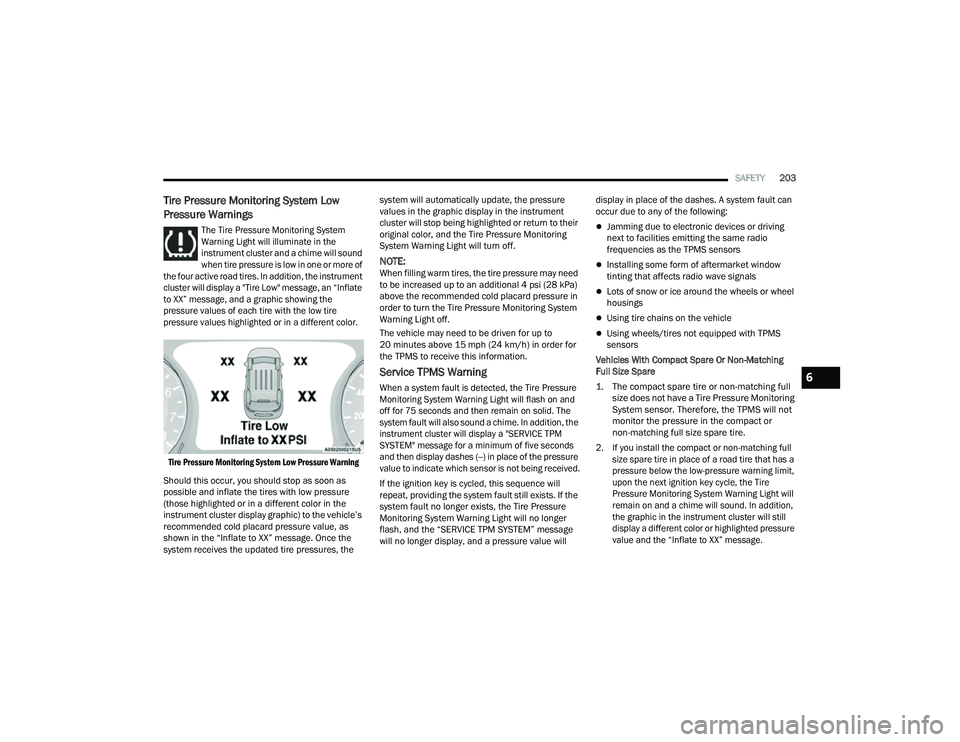
the four active road tires. In addition, the instrument
cluster will display a "Tire Low" message, an “Inflate
to XX” message, and a graphic showing the
pressure values of each tire with the low tire
pressure values highlighted or in a different color.
Tire Pressure Monitoring System Low Pressure Warning
Should this occur, you should stop as soon as
possible and inflate the tires with low pressure
(those highlighted or in a different color in the
instrument cluster display graphic) to the vehicle’s
recommended cold placard pressure value, as
shown in the “Inflate to XX” message. Once the
system receives the updated tire pressures, the system will automatically update, the pressure
values in the graphic display in the instrument
cluster will stop being highlighted or return to their
original color, and the Tire Pressure Monitoring
System Warning Light will turn off.
NOTE:When filling warm tires, the tire pressure may need
to be increased up to an additional 4 psi (28 kPa)
above the recommended cold placard pressure in
order to turn the Tire Pressure Monitoring System
Warning Light off.
The vehicle may need to be driven for up to
20 minutes above 15 mph (24 km/h) in order for
the TPMS to receive this information.
Service TPMS Warning
When a system fault is detected, the Tire Pressure
Monitoring System Warning Light will flash on and
off for 75 seconds and then remain on solid. The
system fault will also sound a chime. In addition, the
instrument cluster will display a "SERVICE TPM
SYSTEM" message for a minimum of five seconds
and then display dashes (--) in place of the pressure
value to indicate which sensor is not being received.
If the ignition key is cycled, this sequence will
repeat, providing the system fault still exists. If the
system fault no longer exists, the Tire Pressure
Monitoring System Warning Light will no longer
flash, and the “SERVICE TPM SYSTEM” message
will no longer display, and a pressure value will
display in place of the dashes. A system fault can
occur due to any of the following:
Jamming due to electronic devices or driving
next to facilities emitting the same radio
frequencies as the TPMS sensors
Installing some form of aftermarket window
tinting that affects radio wave signals
Lots of snow or ice around the wheels or wheel
housings
Using tire chains on the vehicle
Using wheels/tires not equipped with TPMS
sensors
Vehicles With Compact Spare Or Non-Matching
Full Size Spare
1. The compact spare tire or non-matching full size does not have a Tire Pressure Monitoring
System sensor. Therefore, the TPMS will not
monitor the pressure in the compact or
non-matching full size spare tire.
2. If you install the compact or non-matching full size spare tire in place of a road tire that has a
pressure below the low-pressure warning limit,
upon the next ignition key cycle, the Tire
Pressure Monitoring System Warning Light will
remain on and a chime will sound. In addition,
the graphic in the instrument cluster will still
display a different color or highlighted pressure
value and the “Inflate to XX” message.
6
22_MP_OM_EN_USC_t.book Page 203
Page 206 of 344
204SAFETY
3. After driving the vehicle for up to 20 minutes above 15 mph (24 km/h), the Tire Pressure
Monitoring System Warning Light will flash on
and off for 75 seconds and then remain on
solid. In addition, the instrument cluster will
display a “SERVICE TPM SYSTEM” message for
five seconds and then display dashes (--) in
place of the pressure value.
4. For each subsequent ignition key cycle, a chime will sound, the Tire Pressure Monitoring
System Warning Light will flash on and off for
75 seconds and then remain on solid, and the
instrument cluster will display a “SERVICE TPM
SYSTEM” message for five seconds and then
display dashes (--) in place of the pressure
value.
5. Once you repair or replace the original road tire and reinstall it on the vehicle in place of the
compact spare or non-matching full size, the
TPMS will update automatically. In addition,
the Tire Pressure Monitoring System Warning
Light will turn off and the graphic in the
instrument cluster will display a new pressure
value instead of dashes (--), as long as no tire
pressure is below the low-pressure warning
limit in any of the four active road tires.
The vehicle may need to be driven for up to
20 minutes above 15 mph (24 km/h) in order
for the TPMS to receive this information.
TPMS Deactivation — If Equipped
The TPMS can be deactivated if replacing all four
wheel and tire assemblies (road tires) with wheel
and tire assemblies that do not have TPMS
sensors, such as when installing winter wheel and
tire assemblies on your vehicle.
To deactivate the TPMS, first replace all four wheel
and tire assemblies (road tires) with tires not
equipped with Tire Pressure Monitoring System
(TPMS) sensors. Then, drive the vehicle for
20 minutes above 15 mph (24 km/h). The TPMS
will chime, the Tire Pressure Monitoring System
Warning Light will flash on and off for 75 seconds
and then remain on. The instrument cluster will
display the “SERVICE TPM SYSTEM” message and
then display dashes (--) in place of the pressure
values.
Beginning with the next ignition cycle, the TPMS
will no longer chime or display the “SERVICE TPM
SYSTEM” message in the instrument cluster but
dashes (--) will remain in place of the pressure
values.
To reactivate the TPMS, replace all four wheel and
tire assemblies (road tires) with tires equipped with
TPMS sensors. Then, drive the vehicle for up to
20 minutes above 15 mph (24 km/h). The TPMS
will chime, the Tire Pressure Monitoring System
Warning Light will flash on and off for 75 seconds and then turn off. The instrument cluster will
display the “SERVICE TPM SYSTEM” message and
then display pressure values in place of the
dashes. On the next ignition cycle the "SERVICE
TPM SYSTEM" message will no longer be displayed
as long as no system fault exists.
OCCUPANT RESTRAINT SYSTEMS
Some of the most important safety features in your
vehicle are the restraint systems:
OCCUPANT RESTRAINT SYSTEMS
F
EATURES
Seat Belt Systems
Supplemental Restraint Systems (SRS) Air Bags
Child Restraints
Some of the safety features described in this
section may be standard equipment on some
models, or may be optional equipment on others.
If you are not sure, ask an authorized dealer.
IMPORTANT SAFETY PRECAUTIONS
Please pay close attention to the information in
this section. It tells you how to use your restraint
system properly, to keep you and your passengers
as safe as possible.
22_MP_OM_EN_USC_t.book Page 204
Page 226 of 344

224SAFETY
Enhanced Accident Response System
In the event of an impact, if the communication
network remains intact, and the power remains
intact, depending on the nature of the event, the
Occupant Restraint Controller (ORC) will determine
whether to have the Enhanced Accident Response
System perform the following functions:
Cut off fuel to the engine (if equipped)
Cut off battery power to the electric motor
(if equipped)
Flash hazard lights as long as the battery has
power
Turn on the interior lights, which remain on as
long as the battery has power or for 15 minutes
from the intervention of the Enhanced Accident
Response System
Unlock the power door locks Your vehicle may also be designed to perform any
of these other functions in response to the
Enhanced Accident Response System:
Turn off the Fuel Filter Heater, Turn off the HVAC
Blower Motor, Close the HVAC Circulation Door
Cut off battery power to the:
Engine
Electric Motor (if equipped)
Electric power steering
Brake booster
Electric park brake
Automatic transmission gear selector
Horn
Front wiper
Headlamp washer pump (if equipped)
NOTE:After an accident, remember to cycle the ignition to
the STOP (OFF/LOCK) position and remove the key
from the ignition switch to avoid draining the
battery. Carefully check the vehicle for fuel leaks in
the engine compartment and on the ground near
the engine compartment and fuel tank before
resetting the system and starting the engine. If
there are no fuel leaks or damage to the vehicle
electrical devices (e.g. headlights) after an
accident, reset the system by following the
procedure described below. If you have any doubt,
contact an authorized dealer.
22_MP_OM_EN_USC_t.book Page 224
Page 244 of 344
242SAFETY
(Continued)
PERIODIC SAFETY CHECKS YOU SHOULD
M
AKE OUTSIDE THE VEHICLE
Tires
Examine tires for excessive tread wear and uneven
wear patterns. Check for stones, nails, glass, or
other objects lodged in the tread or sidewall.
Inspect the tread for cuts and cracks. Inspect
sidewalls for cuts, cracks, and bulges. Check the
lug nut/bolt torque for tightness. Check the tires
(including spare) for proper cold inflation pressure.
Lights
Have someone observe the operation of brake
lights and exterior lights while you work the
controls. Check turn signal and high beam
indicator lights on the instrument panel.
Door Latches
Check for proper closing, latching, and locking.
Fluid Leaks
Check area under the vehicle after overnight
parking for fuel, coolant, oil, or other fluid leaks.
Also, if gasoline fumes are detected or if fuel or
brake fluid leaks are suspected, the cause should
be located and corrected immediately.
ONLY use the driver’s side floor mat on the
driver’s side floor area. To check for interfer -
ence, with the vehicle properly parked with the
engine off, fully depress the accelerator, the
brake, and the clutch pedal (if present) to
check for interference. If your floor mat inter -
feres with the operation of any pedal, or is not
secure to the floor, remove the floor mat from
the vehicle and place the floor mat in your
trunk.
ONLY use the passenger’s side floor mat on
the passenger’s side floor area.
ALWAYS make sure objects cannot fall or slide
into the driver’s side floor area when the
vehicle is moving. Objects can become
trapped under accelerator, brake, or clutch
pedals and could cause a loss of vehicle
control.
WARNING!
NEVER place any objects under the floor mat
(e.g., towels, keys, etc.). These objects could
change the position of the floor mat and may
cause interference with the accelerator,
brake, or clutch pedals.
If the vehicle carpet has been removed and
re-installed, always properly attach carpet to
the floor and check the floor mat fasteners are
secure to the vehicle carpet. Fully depress
each pedal to check for interference with the
accelerator, brake, or clutch pedals then
re-install the floor mats.
It is recommended to only use mild soap and
water to clean your floor mats. After cleaning,
always check your floor mat has been properly
installed and is secured to your vehicle using
the floor mat fasteners by lightly pulling mat.
WARNING!
22_MP_OM_EN_USC_t.book Page 242
Page 267 of 344
IN CASE OF EMERGENCY265
(Continued)
WITHOUT THE KEY FOB
Special care must be taken when the vehicle is
towed with the ignition in the OFF mode. The only
approved method of towing without the key fob is
with a flatbed truck. Proper towing equipment is
necessary to prevent damage to the vehicle.
FRONT-WHEEL DRIVE (FWD) MODELS
— W
ITH KEY FOB
FCA US LLC recommends towing your vehicle with
all four wheels OFF the ground using a flatbed.
If flatbed equipment is not available, this vehicle
must be towed with the front wheels OFF the
ground (using a towing dolly, or wheel lift
equipment with the front wheels raised).
Ensure that the Electric Park Brake is released,
and remains released, while being towed. The
Electric Park Brake does not need to be released if
all four wheels are OFF the ground.
4X4 MODELS
FCA US LLC requires towing with all four wheels
OFF the ground.
Acceptable methods are to tow the vehicle on a
flatbed, or with one end of the vehicle raised and
the opposite end on a towing dolly.
CAUTION!
Towing this vehicle in violation of the above
requirements can cause severe engine and/or
transmission damage. Damage from improper
towing is not covered under the New Vehicle
Limited Warranty.
CAUTION!
Front or rear wheel lifts must not be used
(if the remaining wheels are on the ground).
Internal damage to the transmission or
transfer case will occur if a front or rear wheel
lift is used when towing.
Towing this vehicle in violation of the above
requirements can cause severe transmission
and/or transfer case damage. Damage from
improper towing is not covered under the New
Vehicle Limited Warranty.
Proper towing or lifting equipment is required
to prevent damage to your vehicle. Use only
tow bars and other equipment designed for
this purpose, following equipment manufac -
turer's instructions.
Use of safety chains is mandatory. Attach a
tow bar or other towing devices to main struc -
tural members of the vehicle, not to fascia/
bumper or associated brackets.
CAUTION!
7
22_MP_OM_EN_USC_t.book Page 265
Page 268 of 344
266IN CASE OF EMERGENCY
EMERGENCY TOW HOOKS —
I
F EQUIPPED
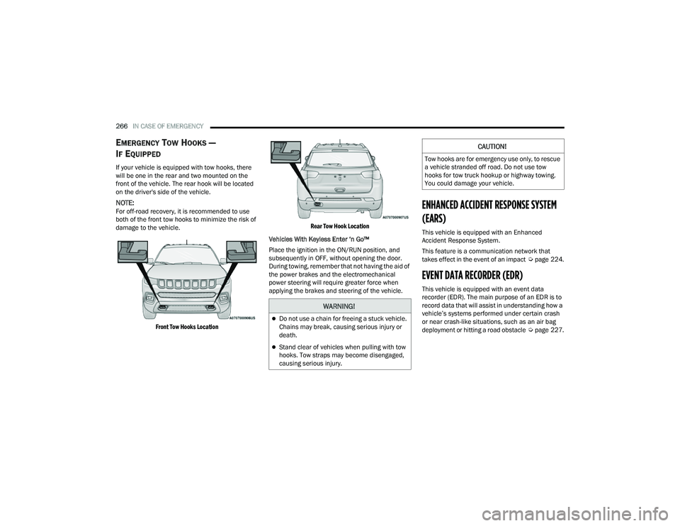
If your vehicle is equipped with tow hooks, there
will be one in the rear and two mounted on the
front of the vehicle. The rear hook will be located
on the driver's side of the vehicle.
NOTE:For off-road recovery, it is recommended to use
both of the front tow hooks to minimize the risk of
damage to the vehicle.
Front Tow Hooks Location Rear Tow Hook Location
Vehicles With Keyless Enter ‘n Go™
Place the ignition in the ON/RUN position, and
subsequently in OFF, without opening the door.
During towing, remember that not having the aid of
the power brakes and the electromechanical
power steering will require greater force when
applying the brakes and steering of the vehicle.ENHANCED ACCIDENT RESPONSE SYSTEM
(EARS)
This vehicle is equipped with an Enhanced
Accident Response System.
This feature is a communication network that
takes effect in the event of an impact Úpage 224.
EVENT DATA RECORDER (EDR)
This vehicle is equipped with an event data
recorder (EDR). The main purpose of an EDR is to
record data that will assist in understanding how a
vehicle’s systems performed under certain crash
or near crash-like situations, such as an air bag
deployment or hitting a road obstacle Úpage 227.
WARNING!
Do not use a chain for freeing a stuck vehicle.
Chains may break, causing serious injury or
death.
Stand clear of vehicles when pulling with tow
hooks. Tow straps may become disengaged,
causing serious injury.
CAUTION!
Tow hooks are for emergency use only, to rescue
a vehicle stranded off road. Do not use tow
hooks for tow truck hookup or highway towing.
You could damage your vehicle.
22_MP_OM_EN_USC_t.book Page 266
Page 292 of 344
290SERVICING AND MAINTENANCE
Interior Fuses
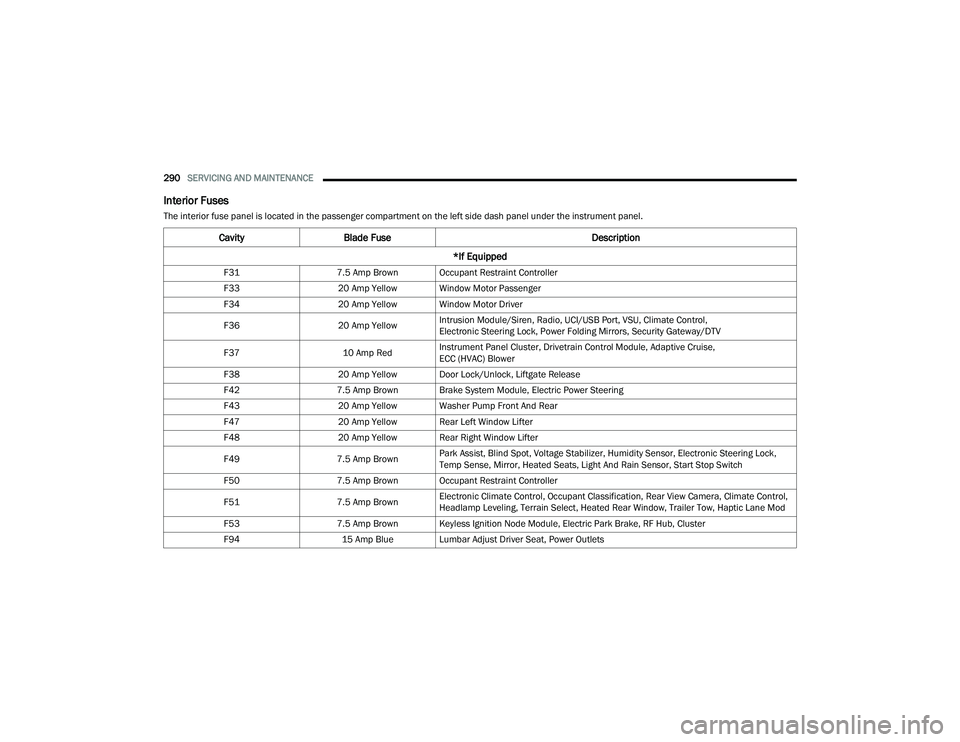
The interior fuse panel is located in the passenger compartment on the left side dash panel under the instrument panel.
CavityBlade Fuse Description
*If Equipped
F31 7.5 Amp Brown Occupant Restraint Controller
F33 20 Amp Yellow Window Motor Passenger
F34 20 Amp Yellow Window Motor Driver
F36 20 Amp YellowIntrusion Module/Siren, Radio, UCI/USB Port, VSU, Climate Control,
Electronic Steering Lock, Power Folding Mirrors, Security Gateway/DTV
F37 10 Amp RedInstrument Panel Cluster, Drivetrain Control Module, Adaptive Cruise,
ECC (HVAC) Blower
F38 20 Amp Yellow Door Lock/Unlock, Liftgate Release
F42 7.5 Amp Brown Brake System Module, Electric Power Steering
F43 20 Amp Yellow Washer Pump Front And Rear
F47 20 Amp Yellow Rear Left Window Lifter
F48 20 Amp Yellow Rear Right Window Lifter
F49 7.5 Amp BrownPark Assist, Blind Spot, Voltage Stabilizer, Humidity Sensor, Electronic Steering Lock,
Temp Sense, Mirror, Heated Seats, Light And Rain Sensor, Start Stop Switch
F50 7.5 Amp Brown Occupant Restraint Controller
F51 7.5 Amp BrownElectronic Climate Control, Occupant Classification, Rear View Camera, Climate Control,
Headlamp Leveling, Terrain Select, Heated Rear Window, Trailer Tow, Haptic Lane Mod
F53 7.5 Amp Brown Keyless Ignition Node Module, Electric Park Brake, RF Hub, Cluster
F94 15 Amp Blue Lumbar Adjust Driver Seat, Power Outlets
22_MP_OM_EN_USC_t.book Page 290
Page 331 of 344
329
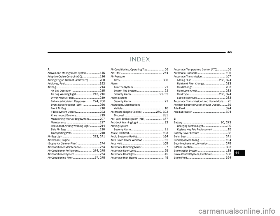
INDEX
A
Active Lane Management System................. 145Adaptive Cruise Control (ACC)........................ 116Adding Engine Coolant (Antifreeze)............... 280Additives, Fuel............................................... 322Air Bag........................................................... 214Air Bag Operation...................................... 215Air Bag Warning Light...................... 213, 216Driver Knee Air Bag................................... 219Enhanced Accident Response......... 224, 266Event Data Recorder (EDR)....................... 266Front Air Bag............................................. 216If Deployment Occurs................................ 223Knee Impact Bolsters................................ 219Maintaining Your Air Bag System.............. 227Maintenance............................................. 227Redundant Air Bag Warning Light.............214Side Air Bags............................................. 220Transporting Pets...................................... 240Air Bag Light........................................ 213, 241Air Cleaner, Engine
(Engine Air Cleaner Filter).............................. 274Air Conditioner Maintenance......................... 274Air Conditioner Refrigerant.................. 274, 275Air Conditioner System.................................. 274Air Conditioning Filter............................. 57, 275
Air Conditioning, Operating Tips....................... 56Air Filter........................................................ 274Air PressureTires......................................................... 306AlarmArm The System.......................................... 21Disarm The System..................................... 22Security Alarm...................................... 21, 92Alarm SystemSecurity Alarm............................................. 21Alterations/ModificationsVehicle......................................................... 10Antifreeze (Engine Coolant)................. 280, 323Disposal................................................... 281Anti-Lock Brake System (ABS)...................... 187Anti-Lock Warning Light................................... 92Arming SystemSecurity Alarm............................................. 21Assist, Hill Start............................................. 193Audio Systems (Radio).................................. 164Auto Down Power Windows............................. 62Auto Hold...................................................... 105Automatic Dimming Mirror............................... 37Automatic Door Locks...................................... 25Automatic Headlights....................................... 45Automatic High Beams.................................... 45
Automatic Temperature Control (ATC)..............56Automatic Transaxle..................................... 106Automatic Transmission................................ 107Adding Fluid..................................... 283, 324Fluid And Filter Change............................. 283Fluid Change............................................. 283Fluid Level Check...................................... 283Fluid Type........................................ 283, 324Special Additives...................................... 283Automatic Transmission Limp Home Mode......25Auxiliary Electrical Outlet (Power Outlet)..........59Axle Fluid....................................................... 324Axle Lubrication............................................ 324
B
Battery................................................... 90, 272Charging System Light.................................90Keyless Key Fob Replacement....................15Battery Saver Feature......................................88Belts, Seat.................................................... 241Blind Spot Monitoring................................... 194Body Mechanism Lubrication........................ 275B-Pillar Location............................................ 303Brake Assist System..................................... 188Brake Control System, Electronic.................. 188Brake Fluid.................................................... 324
11
22_MP_OM_EN_USC_t.book Page 329