Panel JEEP GLADIATOR 2023 User Guide
[x] Cancel search | Manufacturer: JEEP, Model Year: 2023, Model line: GLADIATOR, Model: JEEP GLADIATOR 2023Pages: 448, PDF Size: 17.37 MB
Page 54 of 448
52GETTING TO KNOW YOUR VEHICLE
POWER MIRRORS — IF EQUIPPED
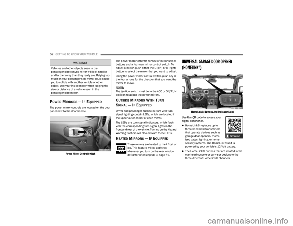
The power mirror controls are located on the door
panel next to the door handle.
Power Mirror Control Switch
The power mirror controls consist of mirror select
buttons and a four-way mirror control switch. To
adjust a mirror, push either the L (left) or R (right)
button to select the mirror that you want to adjust.
Using the power mirror control switch, push any of
the four arrows for the direction that you want the
mirror to move.
NOTE:The ignition switch must be in the ACC or ON/RUN
position to adjust the power mirrors.
OUTSIDE MIRRORS WITH TURN
SIGNAL — IF EQUIPPED
Driver and passenger outside mirrors with turn
signal lighting contain LEDs, which are located in
the upper outer corner of each mirror.
The LEDs are turn signal indicators, which flash
with the corresponding turn signal lights in the
front and rear of the vehicle. Turning on the Hazard
Warning flashers will also activate these LEDs.
HEATED MIRRORS — IF EQUIPPED
These mirrors are heated to melt frost or
ice. This feature will be activated
whenever you turn on the rear window
defroster (if equipped) Ú
page 61.
UNIVERSAL GARAGE DOOR OPENER
(HOMELINK®)
HomeLink® Buttons And Indicator Light
Use this QR code to access your
digital experience.
HomeLink® replaces up to
three hand-held transmitters
that operate devices such as
garage door openers, motor -
ized gates, lighting, or home
security systems. The HomeLink® unit is
powered by your vehicle’s 12 Volt battery.
The HomeLink® buttons that are located in the
overhead console or sunvisor designate the
three different HomeLink® channels.
WARNING!
Vehicles and other objects seen in the
passenger side convex mirror will look smaller
and farther away than they really are. Relying too
much on your passenger side mirror could cause
you to collide with another vehicle or other
object. Use your inside mirror when judging the
size or distance of a vehicle seen in the
passenger side mirror.
23_JT_OM_EN_USC_t.book Page 52
Page 58 of 448
56GETTING TO KNOW YOUR VEHICLE
SECURITY
It is advised to erase all channels before you sell or
turn in your vehicle.
To do this, push and hold the two outside buttons
for 20 seconds until the indicator flashes. Note
that all channels will be erased. Individual
channels cannot be erased.
The HomeLink® Universal Transceiver is disabled
when the Vehicle Security system is active.
NOTE:The universal garage door opener only operates
when the engine is running for security reasons
associated with removable tops and doors.
TROUBLESHOOTING TIPS
If you are having trouble programming
HomeLink®, here are some of the most common
solutions:
Replace the battery in the garage door opener
hand-held transmitter.
Push the LEARN button on the garage door
opener to complete the training for a rolling code.
Did you unplug the device for programming and
remember to plug it back in? If you have any problems, or require assistance,
please call toll-free 1-800-355-3515 or, on the
Internet at HomeLink.com for information or
assistance.
EXTERIOR LIGHTS
HEADLIGHT SWITCH
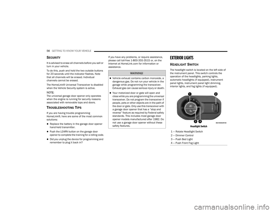
The headlight switch is located on the left side of
the instrument panel. This switch controls the
operation of the headlights, parking lights,
automatic headlights (if equipped), instrument
panel lights, instrument panel light dimming,
interior lights, and fog lights (if equipped).
Headlight Switch
WARNING!
Vehicle exhaust contains carbon monoxide, a
dangerous gas. Do not run your vehicle in the
garage while programming the transceiver.
Exhaust gas can cause serious injury or death.
Your motorized door or gate will open and
close while you are programming the universal
transceiver. Do not program the transceiver if
people, pets or other objects are in the path of
the door or gate. Only use this transceiver with
a garage door opener that has a “stop and
reverse” feature as required by Federal safety
standards. This includes most garage door
opener models manufactured after 1982. Do
not use a garage door opener without these
safety features.
1 — Rotate Headlight Switch
2 — Dimmer Control
3 — Push Bed Light
4 — Push Front Fog Light
23_JT_OM_EN_USC_t.book Page 56
Page 59 of 448
GETTING TO KNOW YOUR VEHICLE57
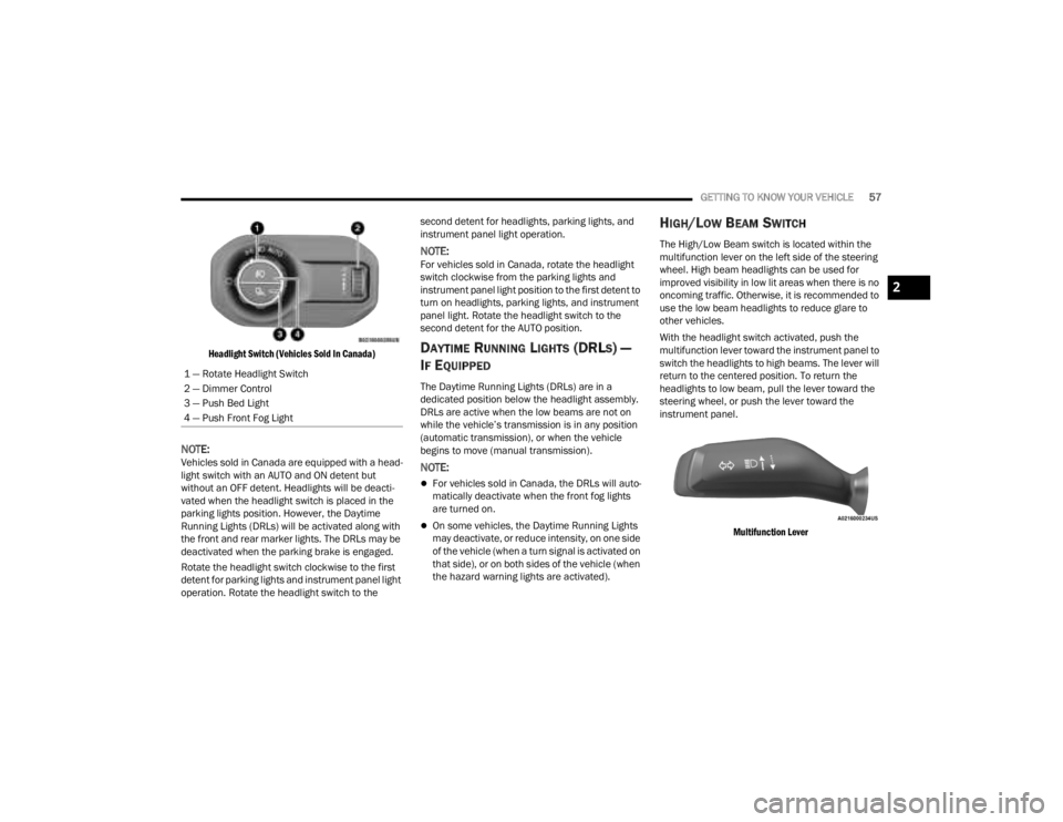
Headlight Switch (Vehicles Sold In Canada)
NOTE:Vehicles sold in Canada are equipped with a head -
light switch with an AUTO and ON detent but
without an OFF detent. Headlights will be deacti -
vated when the headlight switch is placed in the
parking lights position. However, the Daytime
Running Lights (DRLs) will be activated along with
the front and rear marker lights. The DRLs may be
deactivated when the parking brake is engaged.
Rotate the headlight switch clockwise to the first
detent for parking lights and instrument panel light
operation. Rotate the headlight switch to the second detent for headlights, parking lights, and
instrument panel light operation.
NOTE:For vehicles sold in Canada, rotate the headlight
switch clockwise from the parking lights and
instrument panel light position to the first detent to
turn on headlights, parking lights, and instrument
panel light. Rotate the headlight switch to the
second detent for the AUTO position.
DAYTIME RUNNING LIGHTS (DRLS) —
I
F EQUIPPED
The Daytime Running Lights (DRLs) are in a
dedicated position below the headlight assembly.
DRLs are active when the low beams are not on
while the vehicle’s transmission is in any position
(automatic transmission), or when the vehicle
begins to move (manual transmission).
NOTE:
For vehicles sold in Canada, the DRLs will auto -
matically deactivate when the front fog lights
are turned on.
On some vehicles, the Daytime Running Lights
may deactivate, or reduce intensity, on one side
of the vehicle (when a turn signal is activated on
that side), or on both sides of the vehicle (when
the hazard warning lights are activated).
HIGH/LOW BEAM SWITCH
The High/Low Beam switch is located within the
multifunction lever on the left side of the steering
wheel. High beam headlights can be used for
improved visibility in low lit areas when there is no
oncoming traffic. Otherwise, it is recommended to
use the low beam headlights to reduce glare to
other vehicles.
With the headlight switch activated, push the
multifunction lever toward the instrument panel to
switch the headlights to high beams. The lever will
return to the centered position. To return the
headlights to low beam, pull the lever toward the
steering wheel, or push the lever toward the
instrument panel.
Multifunction Lever
1 — Rotate Headlight Switch
2 — Dimmer Control
3 — Push Bed Light
4 — Push Front Fog Light
2
23_JT_OM_EN_USC_t.book Page 57
Page 61 of 448
GETTING TO KNOW YOUR VEHICLE59
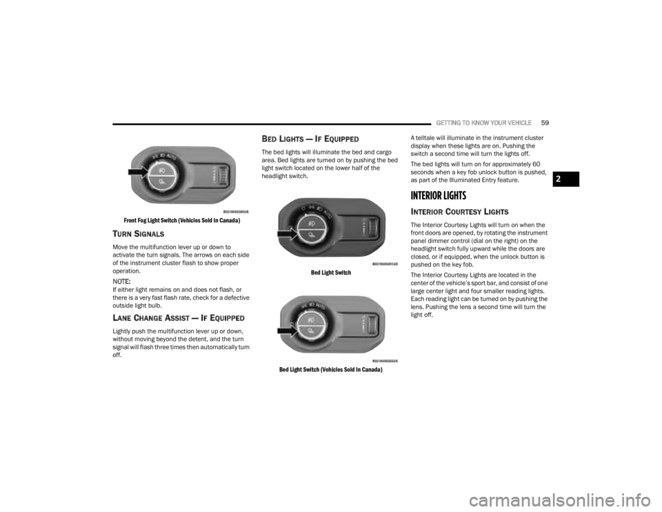
Front Fog Light Switch (Vehicles Sold In Canada)
TURN SIGNALS
Move the multifunction lever up or down to
activate the turn signals. The arrows on each side
of the instrument cluster flash to show proper
operation.
NOTE:If either light remains on and does not flash, or
there is a very fast flash rate, check for a defective
outside light bulb.
LANE CHANGE ASSIST — IF EQUIPPED
Lightly push the multifunction lever up or down,
without moving beyond the detent, and the turn
signal will flash three times then automatically turn
off.
BED LIGHTS — IF EQUIPPED
The bed lights will illuminate the bed and cargo
area. Bed lights are turned on by pushing the bed
light switch located on the lower half of the
headlight switch.
Bed Light Switch
Bed Light Switch (Vehicles Sold In Canada)
A telltale will illuminate in the instrument cluster
display when these lights are on. Pushing the
switch a second time will turn the lights off.
The bed lights will turn on for approximately 60
seconds when a key fob unlock button is pushed,
as part of the Illuminated Entry feature.
INTERIOR LIGHTS
INTERIOR COURTESY LIGHTS
The Interior Courtesy Lights will turn on when the
front doors are opened, by rotating the instrument
panel dimmer control (dial on the right) on the
headlight switch fully upward while the doors are
closed, or if equipped, when the unlock button is
pushed on the key fob.
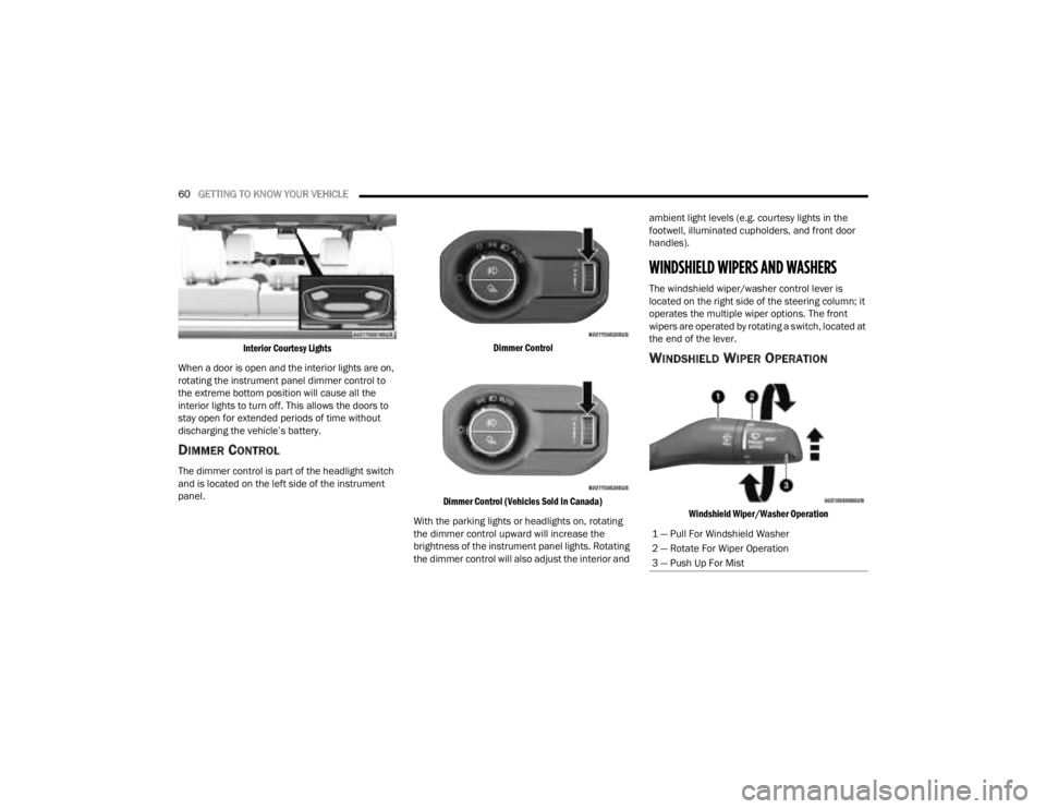
The Interior Courtesy Lights are located in the
center of the vehicle’s sport bar, and consist of one
large center light and four smaller reading lights.
Each reading light can be turned on by pushing the
lens. Pushing the lens a second time will turn the
light off.
2
23_JT_OM_EN_USC_t.book Page 59
Page 62 of 448
60GETTING TO KNOW YOUR VEHICLE
Interior Courtesy Lights
When a door is open and the interior lights are on,
rotating the instrument panel dimmer control to
the extreme bottom position will cause all the
interior lights to turn off. This allows the doors to
stay open for extended periods of time without
discharging the vehicle’s battery.
DIMMER CONTROL
The dimmer control is part of the headlight switch
and is located on the left side of the instrument
panel.
Dimmer Control
Dimmer Control (Vehicles Sold In Canada)
With the parking lights or headlights on, rotating
the dimmer control upward will increase the
brightness of the instrument panel lights. Rotating
the dimmer control will also adjust the interior and ambient light levels (e.g. courtesy lights in the
footwell, illuminated cupholders, and front door
handles).
WINDSHIELD WIPERS AND WASHERS
The windshield wiper/washer control lever is
located on the right side of the steering column; it
operates the multiple wiper options. The front
wipers are operated by rotating a switch, located at
the end of the lever.
WINDSHIELD WIPER OPERATION
Windshield Wiper/Washer Operation
1 — Pull For Windshield Washer
2 — Rotate For Wiper Operation
3 — Push Up For Mist
23_JT_OM_EN_USC_t.book Page 60
Page 63 of 448

GETTING TO KNOW YOUR VEHICLE61
Rotate the end of the lever upward to the first
detent past the intermittent settings for low-speed
wiper operation. Rotate the end of the lever
upward to the second detent past the intermittent
settings for high-speed wiper operation.
Intermittent Wipers
Use the intermittent wiper when weather
conditions make a single wiping cycle, with a
variable pause between cycles, desirable. Rotate
the end of the lever to the first detent position for
one of four intermittent settings. The delay cycle
can be set anywhere between 1 to 18 seconds.
NOTE:The wiper delay times depend on vehicle speed. If
the vehicle is moving less than 10 mph (16 km/h),
delay times will be doubled. Windshield Washers
To use the washer, pull the lever toward you and
hold until desired spray is reached. If the lever is
pulled while in the delay range, the wiper will start
and continue to operate for two or three wipe
cycles after the lever is released. Then, the
intermittent interval previously selected will
resume.
If the lever is pulled while in the off position, the
wipers will operate for two or three wipe cycles.
Then, the wipers will turn off.
NOTE:As a protective measure, the washer will stop if the
switch is held for more than 20 seconds. Once the
switch is released the washer will resume normal
operation.
Mist
Push upward on the wiper lever to activate a single
wipe to clear off-road mist or spray from a passing
vehicle. As long as the lever is held up, the wipers
will continue to operate.
NOTE:The mist feature does not activate the washer
pump; therefore, no washer fluid will be sprayed on
the windshield. The washer function must be used
in order to spray the windshield with washer fluid.
For information on wiper care and replacement,
see Ú
page 374.
CLIMATE CONTROLS
The Climate Control system allows you to regulate
the temperature, air flow, and direction of air
circulating throughout the vehicle. The controls are
located on the touchscreen and on the instrument
panel below the radio.
CAUTION!
In cold weather, always turn off the wiper switch
and allow the wipers to return to the park
position before turning off the engine. If the
wiper switch is left on and the wipers freeze to
the windshield, damage to the wiper motor may
occur when the vehicle is restarted.
WARNING!
Sudden loss of visibility through the windshield
could lead to a collision. You might not see other
vehicles or other obstacles. To avoid sudden
icing of the windshield during freezing weather,
warm the windshield with the defroster before
and during windshield washer use.
2
23_JT_OM_EN_USC_t.book Page 61
Page 66 of 448
64GETTING TO KNOW YOUR VEHICLE
Blower Control
Blower Control regulates the amount of
air forced through the Climate Control
system. There are seven blower speeds
available. Adjusting the blower will cause
automatic mode to switch to manual operation.
The speeds can be selected using either the
blower control knob on the faceplate or the
buttons on the touchscreen.
Faceplate
The blower speed increases as you turn the blower
control knob clockwise from the lowest blower
setting. The blower speed decreases as you turn
the blower control knob counterclockwise.
Touchscreen
Use the small blower icon to reduce the blower
setting and the large blower icon to increase the
blower setting. Blower can also be selected by
pressing the blower bar area between the icons.
Mode Control
Turn the mode control knob or press one
of the Mode buttons on the touchscreen
to adjust airflow distribution. The airflow
distribution mode can be adjusted so air
comes from the instrument panel outlets, floor
outlets, defrost outlets and demist outlets.
Panel Mode
Air comes from the outlets in the
instrument panel. Each of these outlets
can be individually adjusted to direct the
flow of air. The air vanes of the center
outlets and outboard outlets can be moved up and
down or side to side to regulate airflow direction.
There is a shut-off wheel located below the air
vanes to shut off or adjust the amount of airflow
from these outlets.
Bi-Level Mode
Air comes from the instrument panel
outlets and floor outlets. A slight amount
of air is directed through the defrost and
side window demister outlets.
NOTE:Bi-Level mode is designed under comfort condi -
tions to provide cooler air out of the panel outlets
and warmer air from the floor outlets.
Floor Mode
Air comes from the floor outlets. A slight
amount of air is directed through the
defrost and side window demister
outlets.
Mix Mode
Air is directed through the floor, defrost,
and side window demister outlets. This
setting works best in cold or snowy
conditions that require extra heat to the
windshield. This setting is good for maintaining
comfort while reducing moisture on the
windshield.
Climate Control OFF Button
Press and release this button on the
touchscreen, or push and release the
button on the blower knob to turn the
Climate Control ON/OFF.
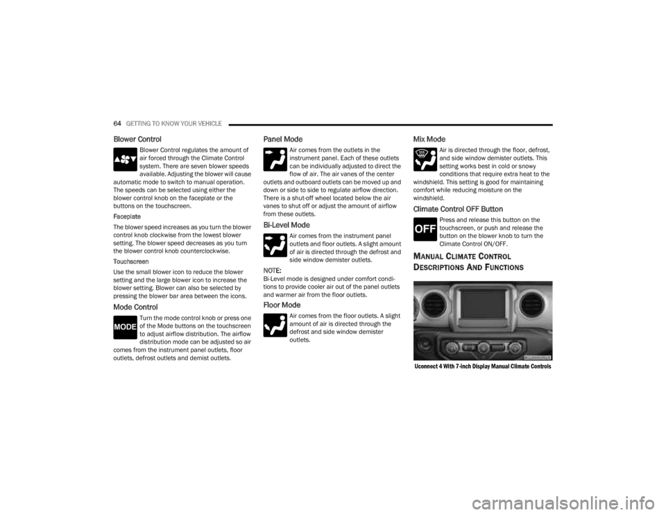
MANUAL CLIMATE CONTROL
D
ESCRIPTIONS AND FUNCTIONS
Uconnect 4 With 7-inch Display Manual Climate Controls
23_JT_OM_EN_USC_t.book Page 64
Page 68 of 448
66GETTING TO KNOW YOUR VEHICLE
Temperature Control
Temperature Control regulates the
temperature of the air forced through the
climate system. The temperature
increases as you turn the temperature
control knob clockwise.
The temperature decreases as you turn
the temperature control knob
counterclockwise. Heater Only
Turning the temperature control knob clockwise
increases the heating temperature and turning the
temperature control knob counterclockwise
decreases the heating temperature.
Blower Control
Blower Control regulates the amount of
air forced through the climate system.
There are seven blower speeds available.
The blower speeds increase as you turn
the blower control knob clockwise from the lowest
blower setting. The blower speed decreases as you
turn the blower control knob counterclockwise.
Mode Control
Turn the mode control knob or press one
of the Mode buttons on the touchscreen
to adjust airflow distribution. The airflow
distribution mode can be adjusted so air
comes from the instrument panel outlets, floor
outlets, defrost outlets and demist outlets.
Panel Mode
Air comes from the outlets in the
instrument panel. Each of these outlets
can be individually adjusted to direct the
flow of air. The air vanes of the center
outlets and outboard outlets can be moved up and
down or side to side to regulate airflow direction.
There is a shut-off wheel located below the air vanes to shut off or adjust the amount of airflow
from these outlets.
Bi-Level Mode
Air comes from the instrument panel
outlets and floor outlets. A slight amount
of air is directed through the defrost and
side window demister outlets.
NOTE:Bi-Level mode is designed under comfort condi
-
tions to provide cooler air out of the panel outlets
and warmer air from the floor outlets.
Floor Mode
Air comes from the floor outlets. A slight
amount of air is directed through the
defrost and side window demister outlets.
Mix Mode
Air is directed through the floor, defrost,
and side window demister outlets. This
setting works best in cold or snowy
conditions that require extra heat to the
windshield. This setting is good for maintaining
comfort while reducing moisture on the
windshield.
Climate Control OFF Button
Press and release this button to turn the
Climate Control ON/OFF.
CAUTION!
Failure to follow these cautions can cause
damage to the heating elements:
Use care when washing the inside of the rear
window. Do not use abrasive window cleaners
on the interior surface of the window. Use a
soft cloth and a mild washing solution, wiping
parallel to the heating elements. Labels can
be peeled off after soaking with warm water.
Do not use scrapers, sharp instruments, or
abrasive window cleaners on the interior
surface of the window.
Keep all objects a safe distance from the
window.
23_JT_OM_EN_USC_t.book Page 66
Page 69 of 448

GETTING TO KNOW YOUR VEHICLE67
AUTOMATIC TEMPERATURE CONTROL
(ATC) — I
F EQUIPPED
Automatic Operation
1. Push the AUTO button on the faceplate, or the
AUTO button on the touchscreen on the
Automatic Temperature Control (ATC) Panel.
2. Next, adjust the temperature that you would like the system to maintain by adjusting the
driver and passenger temperature control
buttons. Once the desired temperature is
displayed, the system will achieve and
automatically maintain that comfort level.
3. When the system is set up for your comfort level, it is not necessary to change the
settings. You will experience the greatest
efficiency by simply allowing the system to
function automatically.
NOTE:
It is not necessary to move the temperature
settings for cold or hot vehicles. The system
automatically adjusts the temperature, mode,
and blower speed to provide comfort as quickly
as possible.
The temperature can be displayed in U.S. or
Metric units by selecting the U.S./Metric
customer-programmable feature within
Uconnect Settings Ú page 215. To provide you with maximum comfort in the
Automatic mode during cold start-ups, the blower
fan will remain on low until the engine warms up.
The blower will increase in speed and transition
into Auto mode.
Manual Operation Override
This system offers a full complement of manual
override features. The AUTO symbol in the front
ATC display will be turned off when the system is
being used in the manual mode.
CLIMATE VOICE COMMANDS
Adjust vehicle temperatures hands-free and keep
everyone comfortable while you keep moving
ahead.
Push the VR button on the steering wheel. After the
beep, say one of the following commands:
“
Set the driver temperature to 70 degrees ”
“Set the passenger temperature to 70 degrees ”
Did You Know:
Voice Command for Climate may
only be used to adjust the interior temperature of
your vehicle. Voice Command will not work to adjust
the heated seats or steering wheel if equipped.
OPERATING TIPS
NOTE:Refer to the chart at the end of this section for
suggested control settings for various weather
conditions.
Summer Operation
The engine cooling system must be protected with
a high-quality antifreeze coolant to provide proper
corrosion protection and to protect against engine
overheating. OAT coolant (conforming to
MS.90032) is recommended.
Winter Operation
To ensure the best possible heater and defroster
performance, make sure the engine cooling
system is functioning properly and the proper
amount, type, and concentration of coolant is
used. Use of the Air Recirculation mode during
Winter months is not recommended, because it
may cause window fogging.
Vacation/Storage
For information on maintaining the Climate Control
system when the vehicle is being stored for an
extended period of time, see Ú page 411.
2
23_JT_OM_EN_USC_t.book Page 67
Page 70 of 448
68GETTING TO KNOW YOUR VEHICLE
Window Fogging
Vehicle windows tend to fog on the inside in mild,
rainy, and/or humid weather. To clear the
windows, select Defrost or Mix mode and increase
the front blower speed. Do not use the
Recirculation mode without A/C for long periods,
as fogging may occur.
Outside Air Intake
Make sure the air intake, located directly in front of
the windshield, is free of obstructions, such as
leaves. Leaves collected in the air intake may
reduce airflow, and if they enter the air distribution
box, they could plug the water drains. In Winter
months, make sure the air intake is clear of ice,
slush, and snow.
Cabin Air Filter
The Climate Control system filters out dust and
pollen from the air. Contact an authorized dealer to
service your cabin air filter, and to have it replaced
when needed.
Stop/Start System — If Equipped
While in an Autostop, the Climate Control system
may automatically adjust airflow to maintain cabin
comfort. Customer settings will be maintained
upon return to an engine running condition.
Operating Tips ChartINTERIOR STORAGE AND EQUIPMENT
STORAGE
Glove Compartment
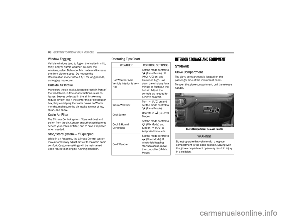
The glove compartment is located on the
passenger side of the instrument panel.
To open the glove compartment, pull the release
handle.
Glove Compartment Release Handle
WEATHER CONTROL SETTINGS
Hot Weather And
Vehicle Interior Is Very
Hot Set the mode control to
(Panel Mode),
(MAX A/C) on, and
blower on high. Roll
down the windows for a
minute to flush out the
hot air. Adjust the
controls as needed to
achieve comfort.
Warm Weather Turn (A/C) on and
set the mode control to
(Panel Mode).
Cool Sunny Operate in (Bi-Level
Mode).
Cool & Humid
Conditions Set the mode control to
(Mix Mode) and
turn on (A/C) to
keep windows clear.
Cold Weather Set the mode control to
(Floor Mode). If
windshield fogging
starts to occur, move
the control to (Mix
Mode).
WARNING!
Do not operate this vehicle with the glove
compartment in the open position. Driving with
the glove compartment open may result in injury
in a collision.
23_JT_OM_EN_USC_t.book Page 68