Panel JEEP GLADIATOR 2023 Owner's Manual
[x] Cancel search | Manufacturer: JEEP, Model Year: 2023, Model line: GLADIATOR, Model: JEEP GLADIATOR 2023Pages: 448, PDF Size: 17.37 MB
Page 73 of 448
GETTING TO KNOW YOUR VEHICLE71
To remove the Fastener Bin:
1. Remove the lid and foam inserts from the Fastener Bin.
2. Remove the three nuts from the bottom of the Fastener Bin.
NOTE:The soft top fasteners do not go in the Fastener
Bin.
Fastener Bin
LIGHTED CUPHOLDERS — IF EQUIPPED
On some vehicles, the front cupholders are
equipped with a light ring that illuminates the
cupholders for the front passengers. The light ring
is controlled by the Dimmer Controls Ú page 60.
AUX/USB CONTROL
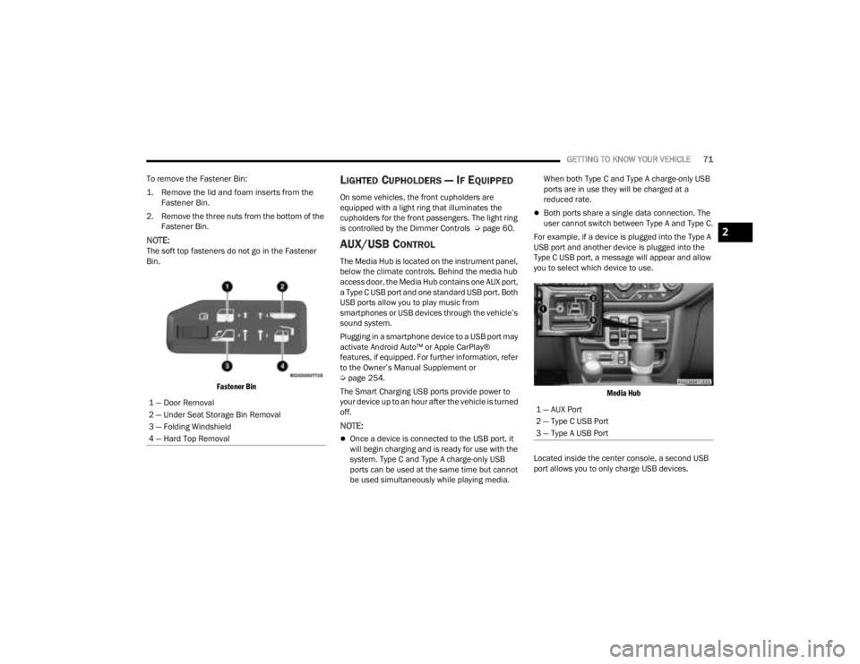
The Media Hub is located on the instrument panel,
below the climate controls. Behind the media hub
access door, the Media Hub contains one AUX port,
a Type C USB port and one standard USB port. Both
USB ports allow you to play music from
smartphones or USB devices through the vehicle’s
sound system.
Plugging in a smartphone device to a USB port may
activate Android Auto™ or Apple CarPlay®
features, if equipped. For further information, refer
to the Owner’s Manual Supplement or
Úpage 254.
The Smart Charging USB ports provide power to
your device up to an hour after the vehicle is turned
off.
NOTE:
Once a device is connected to the USB port, it
will begin charging and is ready for use with the
system. Type C and Type A charge-only USB
ports can be used at the same time but cannot
be used simultaneously while playing media. When both Type C and Type A charge-only USB
ports are in use they will be charged at a
reduced rate.
Both ports share a single data connection. The
user cannot switch between Type A and Type C.
For example, if a device is plugged into the Type A
USB port and another device is plugged into the
Type C USB port, a message will appear and allow
you to select which device to use.
Media Hub
Located inside the center console, a second USB
port allows you to only charge USB devices.
1 — Door Removal
2 — Under Seat Storage Bin Removal
3 — Folding Windshield
4 — Hard Top Removal
1 — AUX Port
2 — Type C USB Port
3 — Type A USB Port
2
23_JT_OM_EN_USC_t.book Page 71
Page 79 of 448
GETTING TO KNOW YOUR VEHICLE77
NOTE:Please refer to the information on the bottom of
the Jeep® wireless speaker for electrical and
safety information before installing or operating
the Jeep® wireless speaker. Directive 2014/53/EU Article 10 Obligations of
Manufacturers
2. Manufacturers shall ensure that radio
equipment shall be so constructed that it can be
operated in at least one Member State without
infringing applicable requirements on the use of
radio spectrum.
10. In cases of restrictions on putting in to service
or of requirements for authorization of use,
information available on the packaging shall allow
the identification of the Member States or the
geographical area within a Member State where
restrictions on putting into service or requirements
for authorization of use exist. The Commission may
adopt implementing acts specifying how to present
that information. Those implementing acts shall be
adopted in accordance with the advisory
procedure referred to in Article 45 (2).
The Bluetooth® word mark and logos are
registered trademarks owned by Bluetooth SIG,
Inc. and any use of such marks by FCA US LLC is
under license. Other trademarks and trade names
are those of their respective owners.
POWER OUTLETS
There is a 12 Volt (13 A) auxiliary power outlet that
can provide power for accessories designed for
use with the standard power outlet adapters.
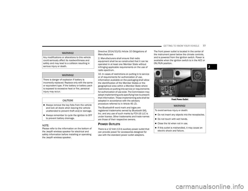
The front power outlet is located in the center of
the instrument panel below the climate controls,
and is powered from the ignition switch. Power is
available when the ignition switch is in the ACC or
ON/RUN position.
Front Power Outlet
WARNING!
Any modifications or alterations to this vehicle
could seriously affect its roadworthiness and
safety and may lead to a collision resulting in
serious injury or death.
WARNING!
There is danger of explosion if battery is
incorrectly replaced. Replace only with the same
or equivalent type. If the battery or battery pack
is exposed to excessive heat or fire, personal
injury may occur.
CAUTION!
Always remove the key fobs from the vehicle
and lock all doors when leaving the vehicle
unattended to prevent theft and/or damage.
Always remember to cycle the ignition to OFF
to prevent battery drainage.
WARNING!
To avoid serious injury or death:
Do not insert any objects into the receptacles.
Do not touch with wet hands.
Close the lid when not in use.
If this outlet is mishandled, it may cause an
electric shock and failure.
2
23_JT_OM_EN_USC_t.book Page 77
Page 80 of 448
78GETTING TO KNOW YOUR VEHICLE
(Continued)
POWER INVERTERS — IF EQUIPPED
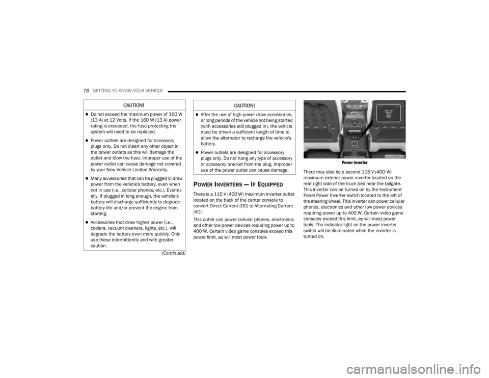
There is a 115 V (400 W) maximum inverter outlet
located on the back of the center console to
convert Direct Current (DC) to Alternating Current
(AC).
This outlet can power cellular phones, electronics
and other low power devices requiring power up to
400 W. Certain video game consoles exceed this
power limit, as will most power tools.
Power Inverter
There may also be a second 115 V (400 W)
maximum exterior power inverter located on the
rear right side of the truck bed near the tailgate.
This inverter can be turned on by the Instrument
Panel Power Inverter switch located to the left of
the steering wheel. This inverter can power cellular
phones, electronics and other low power devices
requiring power up to 400 W. Certain video game
consoles exceed this limit, as will most power
tools. The indicator light on the power inverter
switch will be illuminated when the inverter is
turned on.
CAUTION!
Do not exceed the maximum power of 160 W
(13 A) at 12 Volts. If the 160 W (13 A) power
rating is exceeded, the fuse protecting the
system will need to be replaced.
Power outlets are designed for accessory
plugs only. Do not insert any other object in
the power outlets as this will damage the
outlet and blow the fuse. Improper use of the
power outlet can cause damage not covered
by your New Vehicle Limited Warranty.
Many accessories that can be plugged in draw
power from the vehicle's battery, even when
not in use (i.e., cellular phones, etc.). Eventu -
ally, if plugged in long enough, the vehicle's
battery will discharge sufficiently to degrade
battery life and/or prevent the engine from
starting.
Accessories that draw higher power (i.e.,
coolers, vacuum cleaners, lights, etc.), will
degrade the battery even more quickly. Only
use these intermittently and with greater
caution.
After the use of high power draw accessories,
or long periods of the vehicle not being started
(with accessories still plugged in), the vehicle
must be driven a sufficient length of time to
allow the alternator to recharge the vehicle's
battery.
Power outlets are designed for accessory
plugs only. Do not hang any type of accessory
or accessory bracket from the plug. Improper
use of the power outlet can cause damage.
CAUTION!
23_JT_OM_EN_USC_t.book Page 78
Page 81 of 448
GETTING TO KNOW YOUR VEHICLE79
Power Inverter Switch (If Equipped)
Exterior Truck Bed Power Inverter (If Equipped)
NOTE:400 W is the maximum for the inverter, not each
outlet. If two outlets are in use, 400 W is shared
among the devices plugged in. The power inverter is designed with built-in
overload protection. If the power rating of 400 W is
exceeded, the power inverter automatically shuts
down. Once the electrical device has been
removed from the outlet, the inverter should
automatically reset.
NOTE:
The Power Inverter will only turn on if the ignition
is in the ACC or ON/RUN position.
Due to built-in overload protection, the power
inverter will turn off if the power rating is
exceeded.
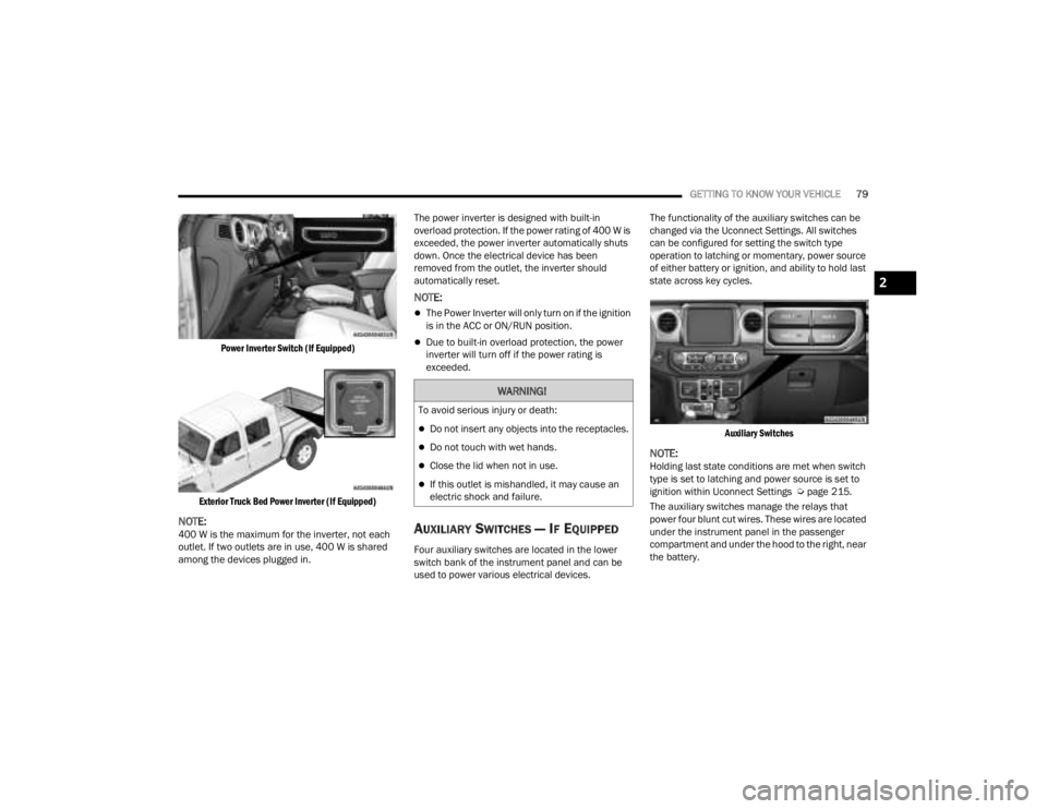
AUXILIARY SWITCHES — IF EQUIPPED
Four auxiliary switches are located in the lower
switch bank of the instrument panel and can be
used to power various electrical devices.The functionality of the auxiliary switches can be
changed via the Uconnect Settings. All switches
can be configured for setting the switch type
operation to latching or momentary, power source
of either battery or ignition, and ability to hold last
state across key cycles.
Auxiliary Switches
NOTE:Holding last state conditions are met when switch
type is set to latching and power source is set to
ignition within Uconnect Settings Ú page 215.
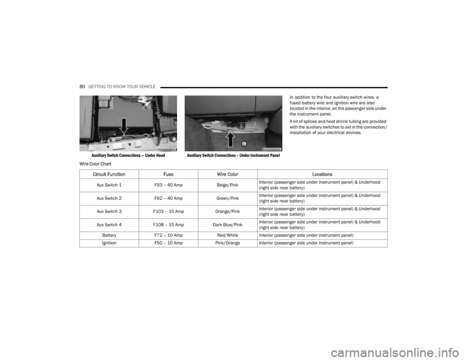
The auxiliary switches manage the relays that
power four blunt cut wires. These wires are located
under the instrument panel in the passenger
compartment and under the hood to the right, near
the battery.
WARNING!
To avoid serious injury or death:
Do not insert any objects into the receptacles.
Do not touch with wet hands.
Close the lid when not in use.
If this outlet is mishandled, it may cause an
electric shock and failure.
2
23_JT_OM_EN_USC_t.book Page 79
Page 82 of 448
80GETTING TO KNOW YOUR VEHICLE
Auxiliary Switch Connections — Under Hood Auxiliary Switch Connections – Under Instrument Panel
In addition to the four auxiliary switch wires, a
fused battery wire and ignition wire are also
located in the interior, on the passenger side under
the instrument panel.
A kit of splices and heat shrink tubing are provided
with the auxiliary switches to aid in the connection/
installation of your electrical devices.
Wire Color Chart
Circuit Function FuseWire Color Locations
Aux Switch 1F93 – 40 Amp Beige/PinkInterior (passenger side under instrument panel) & Underhood
(right side near battery)
Aux Switch 2 F92 – 40 Amp Green/PinkInterior (passenger side under instrument panel) & Underhood
(right side near battery)
Aux Switch 3 F103 – 15 Amp Orange/PinkInterior (passenger side under instrument panel) & Underhood
(right side near battery)
Aux Switch 4 F108 – 15 Amp Dark Blue/PinkInterior (passenger side under instrument panel) & Underhood
(right side near battery)
Battery F72 – 10 Amp Red/White Interior (passenger side under instrument panel)
Ignition F50 – 10 Amp Pink/Orange Interior (passenger side under instrument panel)
23_JT_OM_EN_USC_t.book Page 80
Page 83 of 448
GETTING TO KNOW YOUR VEHICLE81
POWER WINDOWS — IF EQUIPPED
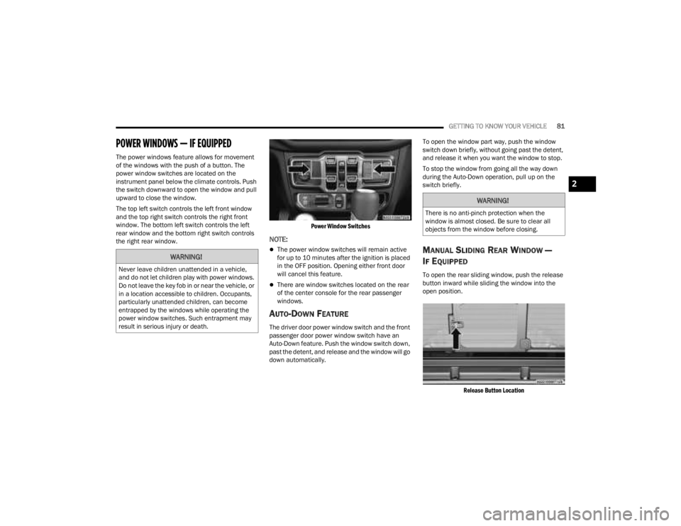
The power windows feature allows for movement
of the windows with the push of a button. The
power window switches are located on the
instrument panel below the climate controls. Push
the switch downward to open the window and pull
upward to close the window.
The top left switch controls the left front window
and the top right switch controls the right front
window. The bottom left switch controls the left
rear window and the bottom right switch controls
the right rear window.
Power Window Switches
NOTE:
The power window switches will remain active
for up to 10 minutes after the ignition is placed
in the OFF position. Opening either front door
will cancel this feature.
There are window switches located on the rear
of the center console for the rear passenger
windows.
AUTO-DOWN FEATURE
The driver door power window switch and the front
passenger door power window switch have an
Auto-Down feature. Push the window switch down,
past the detent, and release and the window will go
down automatically.To open the window part way, push the window
switch down briefly, without going past the detent,
and release it when you want the window to stop.
To stop the window from going all the way down
during the Auto-Down operation, pull up on the
switch briefly.
MANUAL SLIDING REAR WINDOW —
I
F EQUIPPED
To open the rear sliding window, push the release
button inward while sliding the window into the
open position.
Release Button Location
WARNING!
Never leave children unattended in a vehicle,
and do not let children play with power windows.
Do not leave the key fob in or near the vehicle, or
in a location accessible to children. Occupants,
particularly unattended children, can become
entrapped by the windows while operating the
power window switches. Such entrapment may
result in serious injury or death.
WARNING!
There is no anti-pinch protection when the
window is almost closed. Be sure to clear all
objects from the window before closing.
2
23_JT_OM_EN_USC_t.book Page 81
Page 86 of 448
84GETTING TO KNOW YOUR VEHICLE
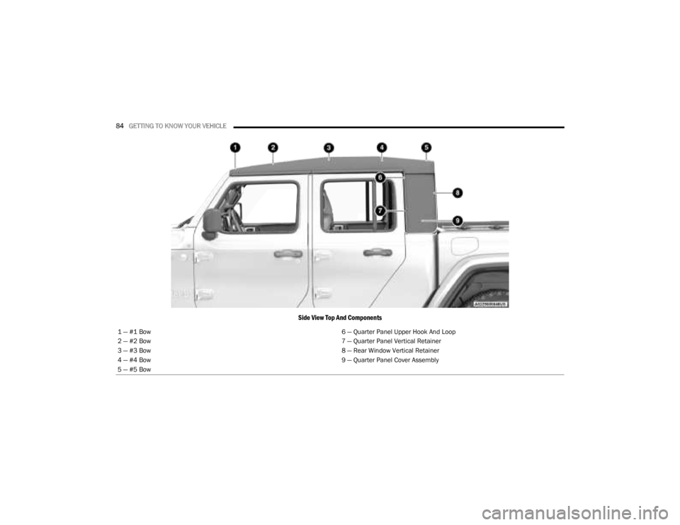
Side View Top And Components
1 — #1 Bow 6 — Quarter Panel Upper Hook And Loop
2 — #2 Bow 7 — Quarter Panel Vertical Retainer
3 — #3 Bow 8 — Rear Window Vertical Retainer
4 — #4 Bow 9 — Quarter Panel Cover Assembly
5 — #5 Bow
23_JT_OM_EN_USC_t.book Page 84
Page 88 of 448
86GETTING TO KNOW YOUR VEHICLE
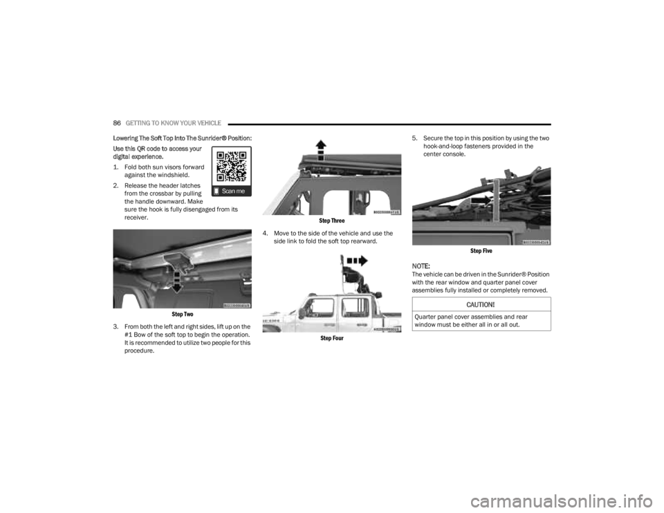
Lowering The Soft Top Into The Sunrider® Position:
Use this QR code to access your
digital experience.
1. Fold both sun visors forward against the windshield.
2. Release the header latches from the crossbar by pulling
the handle downward. Make
sure the hook is fully disengaged from its
receiver.
Step Two
3. From both the left and right sides, lift up on the #1 Bow of the soft top to begin the operation.
It is recommended to utilize two people for this
procedure.
Step Three
4. Move to the side of the vehicle and use the side link to fold the soft top rearward.
Step Four
5. Secure the top in this position by using the two
hook-and-loop fasteners provided in the
center console.
Step Five
NOTE:The vehicle can be driven in the Sunrider® Position
with the rear window and quarter panel cover
assemblies fully installed or completely removed.
CAUTION!
Quarter panel cover assemblies and rear
window must be either all in or all out.
23_JT_OM_EN_USC_t.book Page 86
Page 89 of 448
GETTING TO KNOW YOUR VEHICLE87
Removing The Rear Window And Quarter
Panel Cover Assemblies
NOTE:Both quarter panel cover assemblies and the rear
window must ALL be removed together, or installed
together.
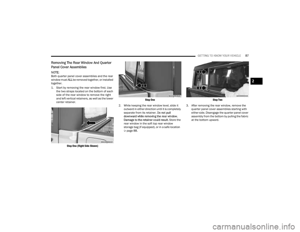
1. Start by removing the rear window first. Use the two straps located on the bottom of each
side of the rear window to remove the right
and left vertical retainers, as well as the lower
center retainer.
Step One (Right Side Shown) Step One
2. While keeping the rear window level, slide it outward in either direction until it is completely
separate from its retainer. Do not pull
downward while removing the rear window.
Damage to the retainer could result. Store the
rear window in the soft top rear window
storage bag (if equipped), or in a safe location
Ú page 88.
Step Two
3. After removing the rear window, remove the quarter panel cover assemblies starting with
either side. Disengage the quarter panel cover
assembly from the bottom by pulling the fabric
at the bottom upward.
2
23_JT_OM_EN_USC_t.book Page 87
Page 90 of 448
88GETTING TO KNOW YOUR VEHICLE
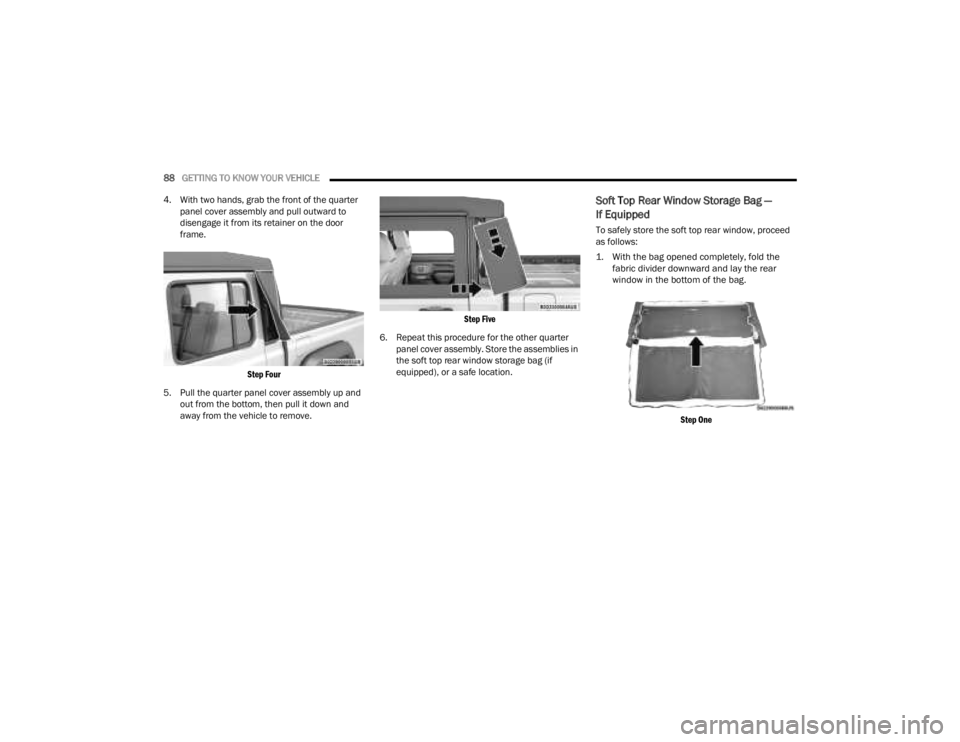
4. With two hands, grab the front of the quarter panel cover assembly and pull outward to
disengage it from its retainer on the door
frame.
Step Four
5. Pull the quarter panel cover assembly up and out from the bottom, then pull it down and
away from the vehicle to remove.
Step Five
6. Repeat this procedure for the other quarter panel cover assembly. Store the assemblies in
the soft top rear window storage bag (if
equipped), or a safe location.
Soft Top Rear Window Storage Bag —
If Equipped
To safely store the soft top rear window, proceed
as follows:
1. With the bag opened completely, fold the fabric divider downward and lay the rear
window in the bottom of the bag.
Step One
23_JT_OM_EN_USC_t.book Page 88