warning lights JEEP GLADIATOR 2023 Owner's Manual
[x] Cancel search | Manufacturer: JEEP, Model Year: 2023, Model line: GLADIATOR, Model: JEEP GLADIATOR 2023Pages: 448, PDF Size: 17.37 MB
Page 168 of 448
166STARTING AND OPERATING
To activate the system, push the AXLE LOCK switch
down to lock the rear axle only (the “REAR ONLY”
will illuminate), push the switch up to lock the front
axle and rear axle (the “FRONT + REAR” will
illuminate). When the rear axle is locked, pushing
the bottom of switch again will lock or unlock the
front axle.
NOTE:The indicator lights will flash until the axles are fully
locked or unlocked.
To unlock the axles, push the AXLE LOCK OFF
button.
Axle Lock will disengage if the vehicle is taken out
of 4L (Four-Wheel Drive Low Range), or the ignition
switch is turned to the OFF position.
The Axle Lock disengages at speeds above 30 mph
(48 km/h), and will automatically re-lock once
vehicle speed is less than 10 mph (16 km/h).
AXLE LOCK (TRU-LOK) REAR ONLY —
I
F EQUIPPED
The rear axle may be locked in 4H if the proper
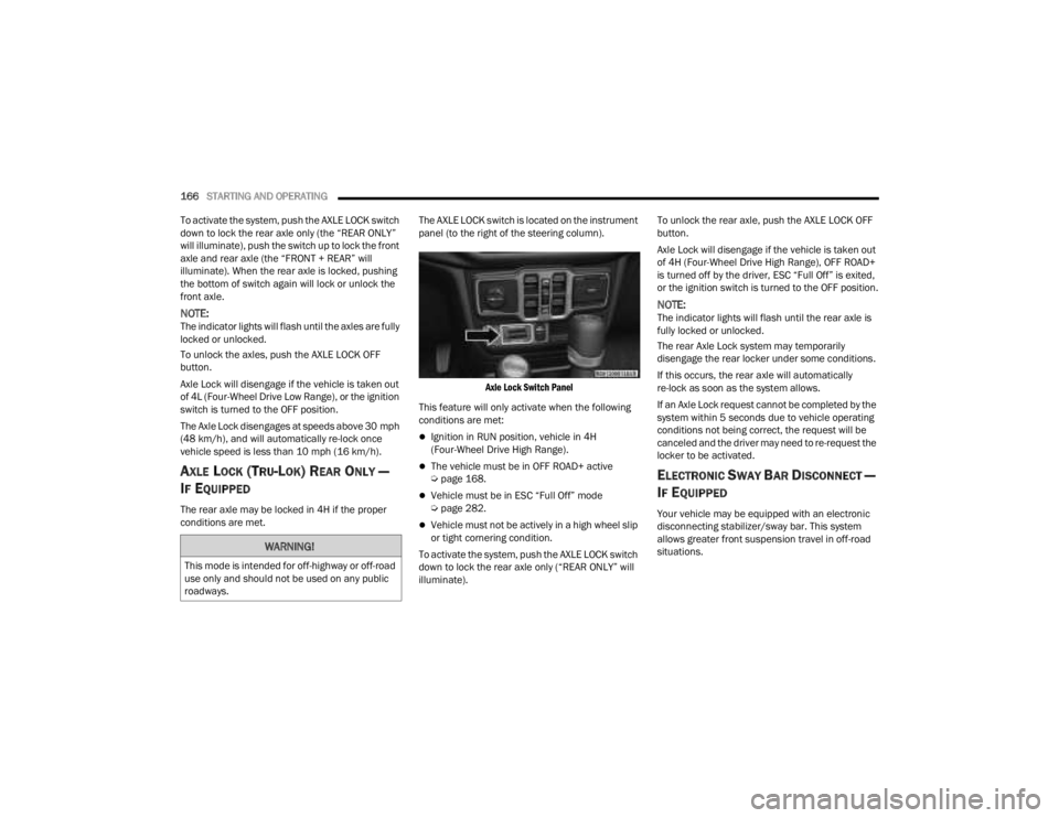
conditions are met. The AXLE LOCK switch is located on the instrument
panel (to the right of the steering column).
Axle Lock Switch Panel
This feature will only activate when the following
conditions are met:
Ignition in RUN position, vehicle in 4H
(Four-Wheel Drive High Range).
The vehicle must be in OFF ROAD+ active
Ú page 168.
Vehicle must be in ESC “Full Off” mode
Úpage 282.
Vehicle must not be actively in a high wheel slip
or tight cornering condition.
To activate the system, push the AXLE LOCK switch
down to lock the rear axle only (“REAR ONLY” will
illuminate). To unlock the rear axle, push the AXLE LOCK OFF
button.
Axle Lock will disengage if the vehicle is taken out
of 4H (Four-Wheel Drive High Range), OFF ROAD+
is turned off by the driver, ESC “Full Off” is exited,
or the ignition switch is turned to the OFF position.
NOTE:The indicator lights will flash until the rear axle is
fully locked or unlocked.
The rear Axle Lock system may temporarily
disengage the rear locker under some conditions.
If this occurs, the rear axle will automatically
re-lock as soon as the system allows.
If an Axle Lock request cannot be completed by the
system within 5 seconds due to vehicle operating
conditions not being correct, the request will be
canceled and the driver may need to re-request the
locker to be activated.
ELECTRONIC SWAY BAR DISCONNECT —
I
F EQUIPPED
Your vehicle may be equipped with an electronic
disconnecting stabilizer/sway bar. This system
allows greater front suspension travel in off-road
situations.
WARNING!
This mode is intended for off-highway or off-road
use only and should not be used on any public
roadways.
23_JT_OM_EN_USC_t.book Page 166
Page 182 of 448
180STARTING AND OPERATING
Setting The Following Distance In ACC
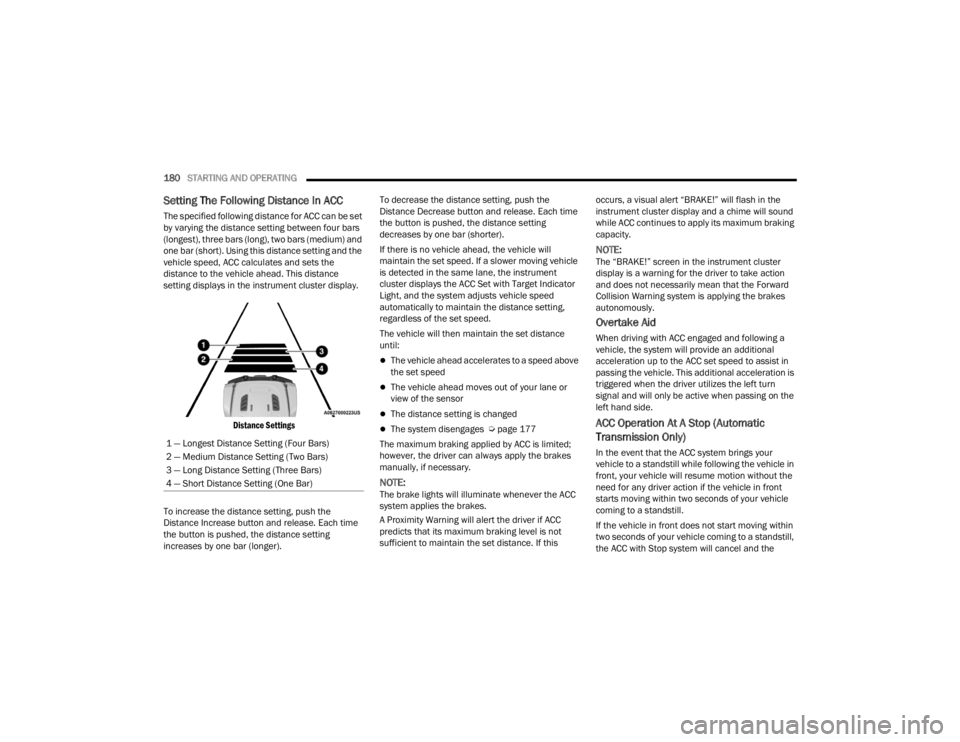
The specified following distance for ACC can be set
by varying the distance setting between four bars
(longest), three bars (long), two bars (medium) and
one bar (short). Using this distance setting and the
vehicle speed, ACC calculates and sets the
distance to the vehicle ahead. This distance
setting displays in the instrument cluster display.
Distance Settings
To increase the distance setting, push the
Distance Increase button and release. Each time
the button is pushed, the distance setting
increases by one bar (longer). To decrease the distance setting, push the
Distance Decrease button and release. Each time
the button is pushed, the distance setting
decreases by one bar (shorter).
If there is no vehicle ahead, the vehicle will
maintain the set speed. If a slower moving vehicle
is detected in the same lane, the instrument
cluster displays the ACC Set with Target Indicator
Light, and the system adjusts vehicle speed
automatically to maintain the distance setting,
regardless of the set speed.
The vehicle will then maintain the set distance
until:
The vehicle ahead accelerates to a speed above
the set speed
The vehicle ahead moves out of your lane or
view of the sensor
The distance setting is changed
The system disengages Ú
page 177
The maximum braking applied by ACC is limited;
however, the driver can always apply the brakes
manually, if necessary.
NOTE:The brake lights will illuminate whenever the ACC
system applies the brakes.
A Proximity Warning will alert the driver if ACC
predicts that its maximum braking level is not
sufficient to maintain the set distance. If this occurs, a visual alert “BRAKE!” will flash in the
instrument cluster display and a chime will sound
while ACC continues to apply its maximum braking
capacity.
NOTE:The “BRAKE!” screen in the instrument cluster
display is a warning for the driver to take action
and does not necessarily mean that the Forward
Collision Warning system is applying the brakes
autonomously.
Overtake Aid
When driving with ACC engaged and following a
vehicle, the system will provide an additional
acceleration up to the ACC set speed to assist in
passing the vehicle. This additional acceleration is
triggered when the driver utilizes the left turn
signal and will only be active when passing on the
left hand side.
ACC Operation At A Stop (Automatic
Transmission Only)
In the event that the ACC system brings your
vehicle to a standstill while following the vehicle in
front, your vehicle will resume motion without the
need for any driver action if the vehicle in front
starts moving within two seconds of your vehicle
coming to a standstill.
If the vehicle in front does not start moving within
two seconds of your vehicle coming to a standstill,
the ACC with Stop system will cancel and the
1 — Longest Distance Setting (Four Bars)
2 — Medium Distance Setting (Two Bars)
3 — Long Distance Setting (Three Bars)
4 — Short Distance Setting (One Bar)
23_JT_OM_EN_USC_t.book Page 180
Page 205 of 448
STARTING AND OPERATING203
Towing Requirements — Tires
Proper tire inflation pressures are essential to
the safe and satisfactory operation of your
vehicle.
Check the trailer tires for proper tire inflation
pressures before trailer usage.
Check for signs of tire wear or visible tire
damage before towing a trailer.
Replacing tires with a higher load carrying
capacity will not increase the vehicle's GVWR
and GAWR limits.
For further information Úpage 395.
Towing Requirements — Trailer Brakes
Do not interconnect the hydraulic brake system
or vacuum system of your vehicle with that of
the trailer. This could cause inadequate braking
and possible personal injury.
An electronically actuated trailer brake
controller is required when towing a trailer with
electronically actuated brakes. When towing a
trailer equipped with a hydraulic surge actuated
brake system, an electronic brake controller is
not required.
NOTE:This vehicle has an aftermarket brake controller
connector under the dash to the left of the brake
pedal. This will be a four pin connector and will be
gray in color.
Trailer brakes are recommended for trailers
over 1,000 lb (453 kg) and required for trailers
in excess of 2,000 lb (907 kg).Towing Requirements — Trailer Lights And
Wiring
Whenever you pull a trailer, regardless of the trailer
size, stop lights and turn signals on the trailer are
required for motoring safety.
The Trailer Tow Package may include a four- and
seven-pin wiring harness. Use a factory approved
trailer harness and connector.
NOTE:Do not cut or splice wiring into the vehicle’s wiring
harness.
The electrical connections are all complete to the
vehicle but you must mate the harness to a trailer
connector. Refer to the following illustrations.
NOTE:
Disconnect the trailer wiring connector from the
vehicle (or any other device plugged into
vehicle’s electrical connectors) before
launching a boat into water.
Be sure to reconnect once clear from water
area.
WARNING!
Do not connect trailer brakes to your vehicle's
hydraulic brake lines. It can overload your
brake system and cause it to fail. You might
not have brakes when you need them and
could have an accident.
Towing any trailer will increase your stopping
distance. When towing, you should allow for
additional space between your vehicle and the
vehicle in front of you. Failure to do so could
result in an accident.
CAUTION!
If the trailer weighs more than 1,000 lb (453 kg)
loaded, it should have its own brakes and they
should be of adequate capacity. Failure to do
this could lead to accelerated brake lining wear,
higher brake pedal effort, and longer stopping
distances.
4
23_JT_OM_EN_USC_t.book Page 203
Page 210 of 448
208STARTING AND OPERATING
3. After all bolts and nuts have been removed, pull the side step assembly off of the vehicle.
4. To reinstall the side steps align the studs to the body side holes and fasten all nuts on all four
brackets. Then secure all four bolts to the
underbody. Repeat the reassembly procedure
for the other side.
Bumper End Cap Removal — If Equipped
The end caps on your vehicle’s front bumper can
be removed by following the steps below:
NOTE:Bumper end caps are removable on steel bumpers
only.
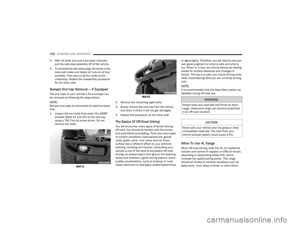
1. Loosen the two bolts that retain the GAWR bracket (Bolts #1 and #2) to the end cap
using a T45 Torx bit screw driver. Do not
remove the bolts.
Bolt #1 Bolt #2
2. Remove the remaining eight bolts.
3. Gently remove the end cap from the vehicle and store it where it will not get damaged.
4. Repeat this procedure on the other side.
The Basics Of Off-Road Driving
You will encounter many types of terrain driving
off-road. You should be familiar with the terrain
and area before proceeding. There are many types
of surface conditions: hard-packed dirt, gravel,
rocks, grass, sand, mud, snow and ice. Every
surface has a different effect on your vehicle's
steering, handling and traction. Controlling your
vehicle is one of the keys to successful off-road
driving, so always keep a firm grip on the steering
wheel and maintain a good driving posture. Avoid
sudden accelerations, turns or braking. In most
cases, there are no road signs, posted speed limits or signal lights. Therefore, you will need to use your
own good judgment on what is safe and what is
not. When on a trail, you should always be looking
ahead for surface obstacles and changes in
terrain. The key is to plan your future driving route
while remembering what you are currently driving
over.
NOTE:It is recommended that the Stop/Start system be
disabled during off-road use.
When To Use 4L Range
When off-road driving, shift into 4L for additional
traction and control on slippery or difficult terrain,
ascending or descending steep hills, and to
increase low speed pulling power. This range
should be limited to extreme situations such as
deep snow, mud, steep inclines, or sand where
WARNING!
Always wear your seat belt and firmly tie down
cargo. Unsecured cargo can become projectiles
in an off-road situation.
CAUTION!
Never park your vehicle over dry grass or other
combustible materials. The heat from your
vehicle exhaust system could cause a fire.
23_JT_OM_EN_USC_t.book Page 208
Page 263 of 448
MULTIMEDIA261
Edit/Edit Profile:
To manage the details of your SiriusXM
Guardian™ account, such as your contact infor -
mation, password and SiriusXM Guardian™ PIN,
click on the Edit/Edit Profile button to access
the details of your account.
Connected Services Status:
This statement will indicate your SiriusXM
Guardian™-equipped vehicle.
Remote Commands:
For vehicles with an active SiriusXM Guardian™
subscription, press one of these icons and enter
your four-digit SiriusXM Guardian™ Security PIN
to remotely start (if equipped), lock/unlock
doors or sound the horn and flash the lights.
Editing Your Notifications
Notifications are an important element of your
SiriusXM Guardian™ account. For example, any
time you use your remote services (such as
Remote Door Unlock), you can elect to receive a
text message, push notification, and/or E-mail to
notify you of the event. To set up the notifications,
please follow these instructions.
1. Log on to your Owner’s Account at
https:// www.mopar.com/en-us.html (US Residents)
and select “Dashboard”, or www.mopar.ca
(Canadian Residents), select “My Vehicle”
and then “Dashboard”.
2. Click the Edit/Edit Profile button.
3. Once there, select “SiriusXM Guardian™”
where you can edit Notification Preferences.
4. You can enter a mobile phone and/or email address to notify you, and you can customize
the types of messages.
USING SIRIUSXM GUARDIAN™
SOS Call — If Equipped
Access To Emergency Services At The Push Of A
Button SiriusXM Guardian™ In-Vehicle Assistance
Features
With SiriusXM Guardian™, your vehicle has
onboard assistance features located on the
rearview mirror or overhead console designed to
enhance your driving experience if you should ever
need assistance or support.
Description
SOS Call offers a convenient way to get in contact
with a SiriusXM Guardian™ Customer Care agent
in the event of an emergency. When the
connection between the vehicle and the live agent
is made, your vehicle will automatically transmit
location information. In the event of a minor
collision, medical or any other emergency, press
the SOS button to be connected to a call center
agent who can send emergency assistance to your
vehicle’s location.
NOTE:Certain SiriusXM Guardian™ connected services
are dependent on an operational Uconnect
system, cellular network availability that is
compatible with the device in your vehicle, and
GPS network availability. Not all features of
SiriusXM Guardian™ are available everywhere at
all times, particularly in remote or enclosed areas.
WARNING!
Some SiriusXM Guardian™ connected services,
including SOS Call and Roadside Assistance
Call, will NOT work without a network connection
compatible with your device.
Center Light Status Description
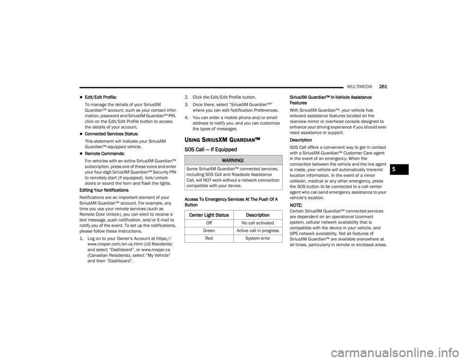
Off
No call activated
Green Active call in progress Red System error
5
23_JT_OM_EN_USC_t.book Page 261
Page 271 of 448
MULTIMEDIA269
on your device, select “Help”, and then select
“SiriusXM Guardian™ Customer Care” to make
the call.
3. SiriusXM Guardian™ Customer Care will authenticate that you are the owner of the
vehicle and contact the law enforcement with
whom you filed the stolen vehicle report.
4. SiriusXM Guardian™ Customer Care will work with your local law enforcement to locate the
vehicle. You will be contacted by law
enforcement if your vehicle is recovered. While
the investigation is ongoing, you should also
contact your insurance company to inform it of
the situation.
Requirements
Vehicle must be properly equipped with the
Uconnect system.
Vehicle must have an operable LTE (voice/data)
or 4G (data) network connection compatible
with your device.
Vehicle must be registered with SiriusXM
Guardian™ and have an active subscription that
includes the applicable feature.
NOTE:Not all features of SiriusXM Guardian™ are
available everywhere at all times, particularly in
remote or enclosed areas.
Monthly Vehicle Health Report —
If Equipped
Description
Monthly Vehicle Health Report is a Uconnect
service through which a summary of the
performance of your vehicle’s key systems will be
sent to you every month so you can stay on top of
your vehicle’s maintenance needs. This is provided
as a convenience to you and does not substitute
for regular maintenance to your vehicle.
In order to provide the Monthly Vehicle Health
Report, the Uconnect system in your vehicle may
collect and transmit vehicle data to SiriusXM
Guardian™ and to FCA, such as your vehicle’s
health and performance, your vehicle’s location,
your utilization of the features in your vehicle, and
other data.
This data collection and transmission begins when
you enroll in SiriusXM Guardian™ and will continue
even if you cancel your SiriusXM Guardian™
subscription unless you call SiriusXM Guardian™
Customer Care and tell them to deactivate your
Uconnect Services.
Please see the Uconnect Privacy Policy for more
information, located at www.driveuconnect.com/
connectedservices/privacy.html (US Residents) or
www.driveuconnect.ca (Canadian Residents). For more information on SiriusXM Guardian™
private policy, see https://siriusxmcvs.com/
privacy-policy.NOTE:Your vehicle must be enrolled in an active
subscription with SiriusXM Guardian™ Connected
Services. If you have concerns about the operation,
function or performance of your vehicle, please
take it to an authorized dealer. This report does not
replace regularly scheduled maintenance. Check
the instrument cluster warning lights and cautions
in your vehicle for the most accurate vehicle health
information.
Vehicle Health Alert —If Equipped
Description
Your vehicle will send you an email alert if it senses
a problem with one of your vehicle’s key systems.
For further information, go to your Owner’s
website.
NOTE:Vehicle Health Alert emails require you to register
and activate services. During this process you will
be asked to provide an email address to which the
reports will be sent.
5
23_JT_OM_EN_USC_t.book Page 269
Page 289 of 448
SAFETY287
NOTE:TSC cannot stop all trailers from swaying. Always
use caution when towing a trailer and follow the
trailer tongue weight recommendations. See
Úpage 197 for further information.
When TSC is functioning, the ESC Activation/
Malfunction Indicator Light will flash, the engine
power may be reduced, and you may feel the
brakes being applied to individual wheels to
attempt to stop the trailer from swaying. TSC is
disabled when the ESC system is in the “Partial
Off” or “Full Off” modes.
AUXILIARY DRIVING SYSTEMS
BLIND SPOT MONITORING (BSM) —
I
F EQUIPPED
The BSM system uses two radar sensors, located
inside the taillights, to detect highway licensable
vehicles (automobiles, trucks, motorcycles, etc.)
that enter the blind spot zones from the rear/front/
side of the vehicle.
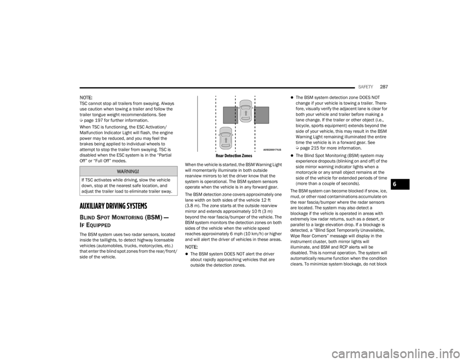
Rear Detection Zones
When the vehicle is started, the BSM Warning Light
will momentarily illuminate in both outside
rearview mirrors to let the driver know that the
system is operational. The BSM system sensors
operate when the vehicle is in any forward gear.
The BSM detection zone covers approximately one
lane width on both sides of the vehicle 12 ft
(3.8 m). The zone starts at the outside rearview
mirror and extends approximately 10 ft (3 m)
beyond the rear fascia/bumper of the vehicle. The
BSM system monitors the detection zones on both
sides of the vehicle when the vehicle speed
reaches approximately 6 mph (10 km/h) or higher
and will alert the driver of vehicles in these areas.
NOTE:
The BSM system DOES NOT alert the driver
about rapidly approaching vehicles that are
outside the detection zones.
The BSM system detection zone DOES NOT
change if your vehicle is towing a trailer. There -
fore, visually verify the adjacent lane is clear for
both your vehicle and trailer before making a
lane change. If the trailer or other object (i.e.,
bicycle, sports equipment) extends beyond the
side of your vehicle, this may result in the BSM
Warning Light remaining illuminated the entire
time the vehicle is in a forward gear. See
Ú page 215 for more information.
The Blind Spot Monitoring (BSM) system may
experience dropouts (blinking on and off) of the
side mirror warning indicator lights when a
motorcycle or any small object remains at the
side of the vehicle for extended periods of time
(more than a couple of seconds).
The BSM system can become blocked if snow, ice,
mud, or other road contaminations accumulate on
the rear fascia/bumper where the radar sensors
are located. The system may also detect a
blockage if the vehicle is operated in areas with
extremely low radar returns, such as a desert, or
parallel to a large elevation drop. If a blockage is
detected, a “Blind Spot Temporarily Unavailable,
Wipe Rear Corners” message will display in the
instrument cluster, both mirror lights will
illuminate, and BSM and RCP alerts will be
disabled. This is normal operation. The system will
automatically resume function when the condition
clears. To minimize system blockage, do not block
WARNING!
If TSC activates while driving, slow the vehicle
down, stop at the nearest safe location, and
adjust the trailer load to eliminate trailer sway.6
23_JT_OM_EN_USC_t.book Page 287
Page 292 of 448
290SAFETY
Rear Cross Path (RCP)
The RCP feature is intended to aid the driver when
backing out of parking spaces where their vision of
oncoming vehicles may be blocked. Proceed slowly
and cautiously out of the parking space until the
rear end of the vehicle is exposed. The RCP system
will then have a clear view of the cross traffic and
if an oncoming vehicle is detected, alert the driver.
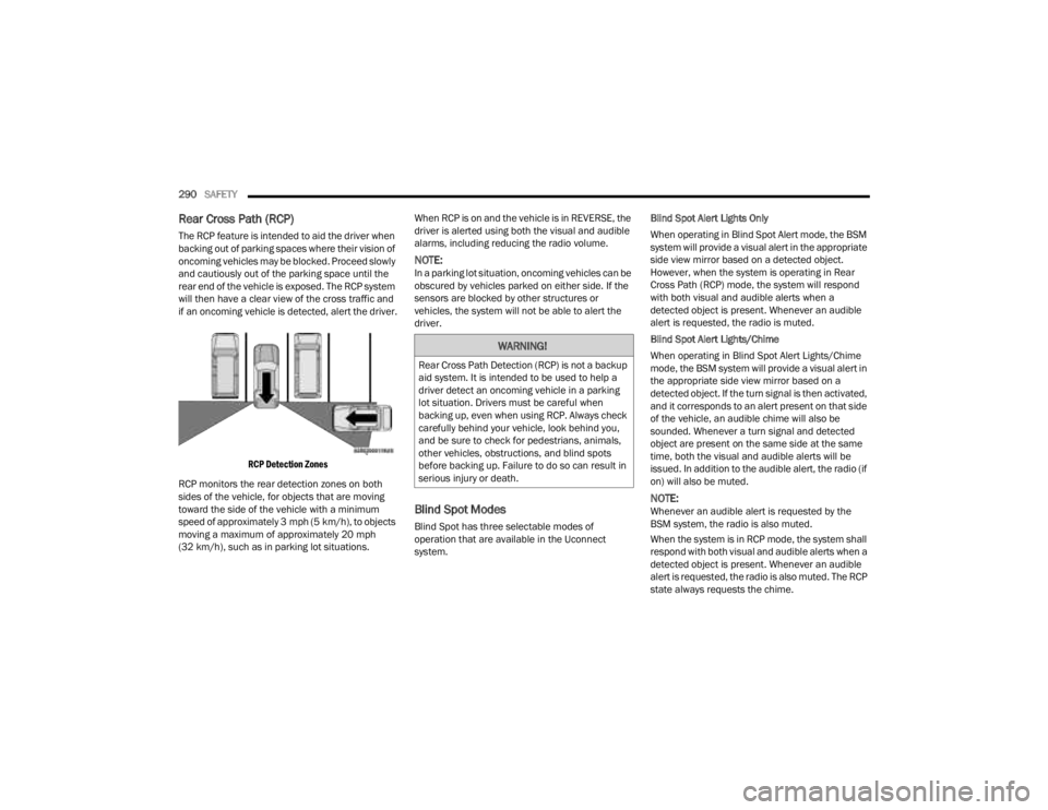
RCP Detection Zones
RCP monitors the rear detection zones on both
sides of the vehicle, for objects that are moving
toward the side of the vehicle with a minimum
speed of approximately 3 mph (5 km/h), to objects
moving a maximum of approximately 20 mph
(32 km/h), such as in parking lot situations. When RCP is on and the vehicle is in REVERSE, the
driver is alerted using both the visual and audible
alarms, including reducing the radio volume.
NOTE:In a parking lot situation, oncoming vehicles can be
obscured by vehicles parked on either side. If the
sensors are blocked by other structures or
vehicles, the system will not be able to alert the
driver.
Blind Spot Modes
Blind Spot has three selectable modes of
operation that are available in the Uconnect
system.Blind Spot Alert Lights Only
When operating in Blind Spot Alert mode, the BSM
system will provide a visual alert in the appropriate
side view mirror based on a detected object.
However, when the system is operating in Rear
Cross Path (RCP) mode, the system will respond
with both visual and audible alerts when a
detected object is present. Whenever an audible
alert is requested, the radio is muted.
Blind Spot Alert Lights/Chime
When operating in Blind Spot Alert Lights/Chime
mode, the BSM system will provide a visual alert in
the appropriate side view mirror based on a
detected object. If the turn signal is then activated,
and it corresponds to an alert present on that side
of the vehicle, an audible chime will also be
sounded. Whenever a turn signal and detected
object are present on the same side at the same
time, both the visual and audible alerts will be
issued. In addition to the audible alert, the radio (if
on) will also be muted.
NOTE:Whenever an audible alert is requested by the
BSM system, the radio is also muted.
When the system is in RCP mode, the system shall
respond with both visual and audible alerts when a
detected object is present. Whenever an audible
alert is requested, the radio is also muted. The RCP
state always requests the chime.
WARNING!
Rear Cross Path Detection (RCP) is not a backup
aid system. It is intended to be used to help a
driver detect an oncoming vehicle in a parking
lot situation. Drivers must be careful when
backing up, even when using RCP. Always check
carefully behind your vehicle, look behind you,
and be sure to check for pedestrians, animals,
other vehicles, obstructions, and blind spots
before backing up. Failure to do so can result in
serious injury or death.
23_JT_OM_EN_USC_t.book Page 290
Page 299 of 448
SAFETY297
Vehicles With A Full-Size Matching Spare
1. If your vehicle is equipped with a matching full-size spare wheel and tire assembly, it has
a Tire Pressure Monitoring System sensor,
and can be monitored by the Tire Pressure
Monitoring System (TPMS) when swapped
with a low pressure road tire.
2. In the event that the matching full-size spare tire is swapped with a low pressure road tire,
the next ignition switch cycle will still show the
TPMS Warning Light to be on, a chime to
sound, an “Inflate to XX” message to appear in
the instrument cluster, and the graphic display
will still show the low tire pressure value in a
different color.
3. Driving the vehicle for up to 20 minutes above 15 mph (24 km/h) will turn off the TPMS
Warning Light as long as none of road tires are
below the low pressure warning threshold.
TIRE FILL ALERT
This feature notifies the user when the placard tire
pressure is attained while inflating or deflating the
tire.
The customer may choose to disable or enable the
Tire Fill Alert feature in the apps menu of the
Uconnect system.
NOTE:
Only one tire can be filled at a time when using
the Tire Fill Alert system.
The Tire Fill Alert feature cannot be entered if an
existing TPMS system fault is set to “active” or if
the system is in deactivation mode (if equipped).
The system will be activated when the system
detects an increase in tire pressure while filling the
tire. The ignition must be in the ON/RUN mode with
the transmission in PARK for vehicles equipped
with an automatic transmission. For vehicles
equipped with a manual transmission, the parking
brake must be applied.
NOTE:It is not required to have the engine running to
enter Tire Fill Alert mode.
The hazard lamps will come on to confirm the
vehicle is in Tire Fill Alert mode. If the hazard lamps
do not come on while inflating the tire, the Tire
Pressure Monitoring System (TPMS) sensor may
be in an inoperative position, preventing the TPMS
sensor signal from being received. In this case, the
vehicle may need to be moved slightly forward or
backward. The Tire Fill Alert system will only inflate or deflate
one tire at a time. Wait until the hazard lights have
stopped flashing for 30 seconds after the desired
pressure is achieved in one tire before switching to
another.
When Tire Fill Alert mode is entered, the tire
pressure display screen will be displayed in the
instrument cluster.
Operation:
The horn will chirp once to let the user know
when to stop filling the tire, when it reaches
recommended pressure.
The horn will chirp three times if the tire is over
-
filled and will continue to chirp every five
seconds if the user continues to inflate the tire.
The horn will chirp once again when enough air
is let out to reach proper inflation level.
The horn will also chirp three times if the tire is
then underinflated and will continue to chirp
every five seconds if the user continues to
deflate the tire.
NOTE:The Tire Fill Alert feature is set to “Disabled” every
time the ignition is turned to “OFF”. To re-enable
the Tire Fill Alert feature at the next ignition “RUN”
state, the customer must re-enable the feature
through use of the customer settings in the radio.
6
23_JT_OM_EN_USC_t.book Page 297
Page 300 of 448
298SAFETY
SELECTABLE TIRE FILL ALERT — IF EQUIPPED
The Selectable Tire Fill Alert (STFA) system is an
optional feature that is included as part of the
normal Tire Fill Alert system. The system is
designed to allow you to select a pressure to inflate
or deflate the vehicle's front and rear axle tires to,
and to provide feedback while inflating or deflating
the vehicle's tires.
In the Selectable Tire Fill Alert application, which is
located in the apps menu of the Uconnect system,
you will be able to select a pressure setting for both
the front and rear axle tire pressures by scrolling
through a pressure range from XX to 15 psi in 1 psi
increments for each axle setting.
XX = the vehicle's cold placard pressure values for
the front and rear axles as shown on the vehicle
placard pressure label.
NOTE:The Tire Fill Alert feature disables every time the
ignition is placed in the OFF position. The feature
must be re-enabled through the radio each time
the ignition is placed back in the ON/RUN position
Úpage 215.
You may also store pressure values chosen for
each axle in the Uconnect system application as
preset pressure values. Up to two sets of preset
pressure values can be stored in the Uconnect
system for the front and rear axle. Once you select
the tire pressures for the front and rear axles that you want to inflate or deflate to, you can begin
inflating or deflating one tire at a time.
NOTE:The STFA system will only support inflating or
deflating one tire at a time.
In order to use STFA, the Tire Fill Alert feature must
be enabled through the radio Ú
page 215.
The system will be activated when the TPMS
receiver module detects a change in tire pressure.
The ignition must be in the ON/RUN mode, with the
transmission in PARK in vehicles with an automatic
transmission, and in NEUTRAL with the parking
brake engaged in vehicles with a manual
transmission. The hazard lamps will come on to
confirm the vehicle is in Tire Fill Alert mode.
When Tire Fill Alert mode is entered, the tire
pressure screen will be displayed in the instrument
cluster. If the hazard lamps do not come on while
inflating or deflating the tire, the Tire Pressure
Monitoring System (TPMS) sensor may be in an
inoperative position, preventing the TPMS sensor
signal from being received. In this case, the vehicle
may need to be moved slightly forward or
backward.
The STFA system will only inflate or deflate one tire
at a time. Wait until the hazard lights have stopped
flashing for 30 seconds after the desired pressure
is achieved on one tire before switching to another. Horn chirps will indicate STFA status as tires are
inflated/deflated. The horn will chirp under the
following STFA states:
1. The horn will chirp once when the selected
pressure is reached to let you know when to
stop inflating or deflating the tire.
2. The horn will chirp three times if the tire is overinflated or over-deflated.
3. The horn will chirp once again when enough air is added or removed to reach proper selected
pressure level.
TPMS DEACTIVATION — IF EQUIPPED
The TPMS can be deactivated if replacing all four
wheel and tire assemblies (road tires) with wheel
and tire assemblies that do not have TPMS
sensors, such as when installing winter wheel and
tire assemblies on your vehicle.
To deactivate the TPMS, first replace all four wheel
and tire assemblies (road tires) with tires not
equipped with Tire Pressure Monitoring System
(TPMS) sensors. Then, drive the vehicle for
20 minutes above 15 mph (24 km/h). The TPMS
will chime, the TPMS Warning Light will flash on
and off for 75 seconds and then remain on. The
instrument cluster will display the “SERVICE TIRE
PRESSURE SYSTEM” message and then display
dashes (--) in place of the pressure values.
23_JT_OM_EN_USC_t.book Page 298