brake light JEEP GLADIATOR 2023 Owner's Guide
[x] Cancel search | Manufacturer: JEEP, Model Year: 2023, Model line: GLADIATOR, Model: JEEP GLADIATOR 2023Pages: 448, PDF Size: 17.37 MB
Page 283 of 448

SAFETY281
power to lessen the chance that wheel lift will
occur. ERM can only reduce the chance of wheel
lift occurring during severe or evasive driving
maneuvers; it cannot prevent wheel lift due to
other factors, such as road conditions, leaving the
roadway, striking objects or other vehicles.
NOTE:ERM is disabled any time the ESC is in “Full Off”
mode (if equipped). See Ú page 281 for a
complete explanation of the available ESC modes.
Electronic Stability Control (ESC)
The ESC system enhances directional control and
stability of the vehicle under various driving
conditions. ESC corrects for oversteering or
understeering of the vehicle by applying the brake of the appropriate wheel(s) to counteract the
above conditions. Engine power may also be
reduced to help the vehicle maintain the desired
path.
Oversteer — when the vehicle is turning more
than appropriate for the steering wheel position.
Understeer — when the vehicle is turning less
than appropriate for the steering wheel position.
ESC uses sensors in the vehicle to determine the
vehicle path intended by the driver and compares
it to the actual path of the vehicle. When the actual
path does not match the intended path, ESC
applies the brake of the appropriate wheel to
assist in counteracting the oversteer or understeer
condition.
The ESC Activation/Malfunction Indicator Light
located in the instrument cluster will start to flash
as soon as the ESC system becomes active. The
ESC Activation/Malfunction Indicator Light also
flashes when the Traction Control System (TCS) is
active. If the ESC Activation/Malfunction Indicator
Light begins to flash during acceleration, ease up
on the accelerator and apply as little throttle as
possible. Be sure to adapt your speed and driving
to the prevailing road conditions.
WARNING!
Many factors, such as vehicle loading, road
conditions and driving conditions, influence the
chance that wheel lift or rollover may occur. ERM
cannot prevent all wheel lift or rollovers,
especially those that involve leaving the roadway
or striking objects or other vehicles. The
capabilities of an ERM-equipped vehicle must
never be exploited in a reckless or dangerous
manner which could jeopardize the user's safety
or the safety of others.
WARNING!
Electronic Stability Control (ESC) cannot
prevent the natural laws of physics from acting
on the vehicle, nor can it increase the traction
afforded by prevailing road conditions. ESC
cannot prevent accidents, including those
resulting from excessive speed in turns, driving
on very slippery surfaces, or hydroplaning. ESC
also cannot prevent accidents resulting from
loss of vehicle control due to inappropriate
driver input for the conditions. Only a safe,
attentive, and skillful driver can prevent acci -
dents. The capabilities of an ESC equipped
vehicle must never be exploited in a reckless or
dangerous manner which could jeopardize the
user’s safety or the safety of others.
Vehicle modifications, or failure to properly
maintain your vehicle, may change the handling
characteristics of your vehicle, and may nega -
tively affect the performance of the ESC system.
Changes to the steering system, suspension,
braking system, tire type and size or wheel size
may adversely affect ESC performance. Improp -
erly inflated and unevenly worn tires may also
degrade ESC performance. Any vehicle modifi-
cation or poor vehicle maintenance that
reduces the effectiveness of the ESC system
can increase the risk of loss of vehicle control,
vehicle rollover, personal injury and death.
6
23_JT_OM_EN_USC_t.book Page 281
Page 285 of 448
SAFETY283
ESC Activation/Malfunction Indicator Light
And ESC OFF Indicator Light
The ESC Activation/Malfunction Indicator
Light in the instrument cluster will come
on when the ignition is placed in the ON/
RUN mode. It should go out with the
engine running. If the ESC Activation/Malfunction
Indicator Light comes on continuously with the
engine running, a malfunction has been detected
in the ESC system. If this light remains on after
several ignition cycles, and the vehicle has been
driven several miles (kilometers) at speeds greater
than 30 mph (48 km/h), see an authorized dealer
as soon as possible to have the problem
diagnosed and corrected.
The ESC Activation/Malfunction Indicator Light
starts to flash as soon as the tires lose traction and
the ESC system becomes active. The ESC
Activation/Malfunction Indicator Light also flashes
when the Traction Control System (TCS) is active. If
the ESC Activation/Malfunction Indicator Light
begins to flash during acceleration, ease up on the
accelerator and apply as little throttle as possible.
Be sure to adapt your speed and driving to the
prevailing road conditions.
NOTE:
The ESC Activation/Malfunction Indicator Light
and the ESC OFF Indicator Light come on
momentarily each time the ignition is placed in
the ON/RUN mode.
Each time the ignition is placed in the ON/RUN
position, the ESC system will be on even if it was
turned off previously.
The ESC system will make buzzing or clicking
sounds when it is active. This is normal; the
sounds will stop when ESC becomes inactive
following the maneuver that caused the ESC
activation.
The ESC OFF Indicator Light indicates
that the Electronic Stability Control (ESC)
is in a reduced mode.
Hill Start Assist (HSA)
The HSA system is designed to mitigate roll back
from a complete stop while on an incline. If the
driver releases the brake while stopped on an
incline, HSA will continue to hold the brake
pressure for a short period. If the driver does not
apply the throttle before this time expires, the
system will release brake pressure and the vehicle
will roll down the hill as normal.
The following conditions must be met in order for
HSA to activate:
The feature must be enabled.
The vehicle must be stopped.
The parking brake must be off.
The driver door must be closed. (If the doors are
attached, then the door must be closed. If the doors are detached then the driver's seat belt
must be buckled.)
The vehicle must be on a sufficient grade.
The gear selection must match vehicle uphill
direction (i.e., vehicle facing uphill is in forward
gear; vehicle backing uphill is in REVERSE gear).
HSA will work in REVERSE gear and all forward
gears. The system will not activate if the trans
-
mission is in PARK or NEUTRAL. For vehicles
equipped with a manual transmission, if the
clutch is pressed, HSA will remain active.
WARNING!
There may be situations where the Hill Start
Assist (HSA) will not activate and slight rolling
may occur, such as on minor hills or with a
loaded vehicle, or while pulling a trailer. HSA is
not a substitute for active driving involvement. It
is always the driver’s responsibility to be
attentive to distance to other vehicles, people,
and objects, and most importantly brake
operation to ensure safe operation of the vehicle
under all road conditions. Your complete
attention is always required while driving to
maintain safe control of your vehicle. Failure to
follow these warnings can result in a collision or
serious personal injury.
6
23_JT_OM_EN_USC_t.book Page 283
Page 289 of 448
SAFETY287
NOTE:TSC cannot stop all trailers from swaying. Always
use caution when towing a trailer and follow the
trailer tongue weight recommendations. See
Úpage 197 for further information.
When TSC is functioning, the ESC Activation/
Malfunction Indicator Light will flash, the engine
power may be reduced, and you may feel the
brakes being applied to individual wheels to
attempt to stop the trailer from swaying. TSC is
disabled when the ESC system is in the “Partial
Off” or “Full Off” modes.
AUXILIARY DRIVING SYSTEMS
BLIND SPOT MONITORING (BSM) —
I
F EQUIPPED
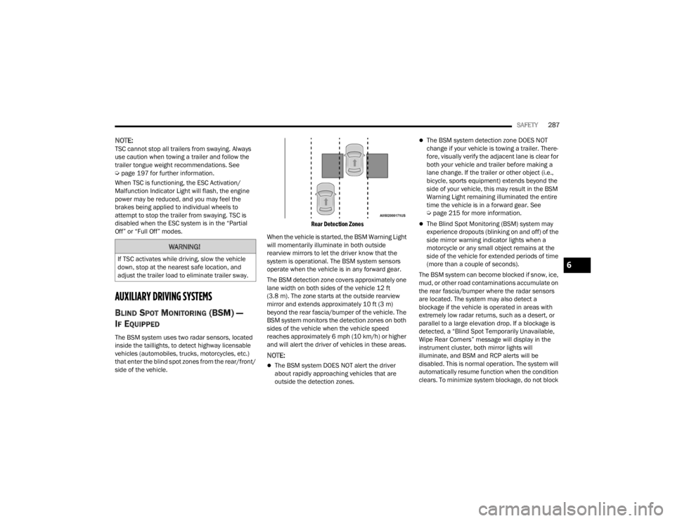
The BSM system uses two radar sensors, located
inside the taillights, to detect highway licensable
vehicles (automobiles, trucks, motorcycles, etc.)
that enter the blind spot zones from the rear/front/
side of the vehicle.
Rear Detection Zones
When the vehicle is started, the BSM Warning Light
will momentarily illuminate in both outside
rearview mirrors to let the driver know that the
system is operational. The BSM system sensors
operate when the vehicle is in any forward gear.
The BSM detection zone covers approximately one
lane width on both sides of the vehicle 12 ft
(3.8 m). The zone starts at the outside rearview
mirror and extends approximately 10 ft (3 m)
beyond the rear fascia/bumper of the vehicle. The
BSM system monitors the detection zones on both
sides of the vehicle when the vehicle speed
reaches approximately 6 mph (10 km/h) or higher
and will alert the driver of vehicles in these areas.
NOTE:
The BSM system DOES NOT alert the driver
about rapidly approaching vehicles that are
outside the detection zones.
The BSM system detection zone DOES NOT
change if your vehicle is towing a trailer. There -
fore, visually verify the adjacent lane is clear for
both your vehicle and trailer before making a
lane change. If the trailer or other object (i.e.,
bicycle, sports equipment) extends beyond the
side of your vehicle, this may result in the BSM
Warning Light remaining illuminated the entire
time the vehicle is in a forward gear. See
Ú page 215 for more information.
The Blind Spot Monitoring (BSM) system may
experience dropouts (blinking on and off) of the
side mirror warning indicator lights when a
motorcycle or any small object remains at the
side of the vehicle for extended periods of time
(more than a couple of seconds).
The BSM system can become blocked if snow, ice,
mud, or other road contaminations accumulate on
the rear fascia/bumper where the radar sensors
are located. The system may also detect a
blockage if the vehicle is operated in areas with
extremely low radar returns, such as a desert, or
parallel to a large elevation drop. If a blockage is
detected, a “Blind Spot Temporarily Unavailable,
Wipe Rear Corners” message will display in the
instrument cluster, both mirror lights will
illuminate, and BSM and RCP alerts will be
disabled. This is normal operation. The system will
automatically resume function when the condition
clears. To minimize system blockage, do not block
WARNING!
If TSC activates while driving, slow the vehicle
down, stop at the nearest safe location, and
adjust the trailer load to eliminate trailer sway.6
23_JT_OM_EN_USC_t.book Page 287
Page 299 of 448
SAFETY297
Vehicles With A Full-Size Matching Spare
1. If your vehicle is equipped with a matching full-size spare wheel and tire assembly, it has
a Tire Pressure Monitoring System sensor,
and can be monitored by the Tire Pressure
Monitoring System (TPMS) when swapped
with a low pressure road tire.
2. In the event that the matching full-size spare tire is swapped with a low pressure road tire,
the next ignition switch cycle will still show the
TPMS Warning Light to be on, a chime to
sound, an “Inflate to XX” message to appear in
the instrument cluster, and the graphic display
will still show the low tire pressure value in a
different color.
3. Driving the vehicle for up to 20 minutes above 15 mph (24 km/h) will turn off the TPMS
Warning Light as long as none of road tires are
below the low pressure warning threshold.
TIRE FILL ALERT
This feature notifies the user when the placard tire
pressure is attained while inflating or deflating the
tire.
The customer may choose to disable or enable the
Tire Fill Alert feature in the apps menu of the
Uconnect system.
NOTE:
Only one tire can be filled at a time when using
the Tire Fill Alert system.
The Tire Fill Alert feature cannot be entered if an
existing TPMS system fault is set to “active” or if
the system is in deactivation mode (if equipped).
The system will be activated when the system
detects an increase in tire pressure while filling the
tire. The ignition must be in the ON/RUN mode with
the transmission in PARK for vehicles equipped
with an automatic transmission. For vehicles
equipped with a manual transmission, the parking
brake must be applied.
NOTE:It is not required to have the engine running to
enter Tire Fill Alert mode.
The hazard lamps will come on to confirm the
vehicle is in Tire Fill Alert mode. If the hazard lamps
do not come on while inflating the tire, the Tire
Pressure Monitoring System (TPMS) sensor may
be in an inoperative position, preventing the TPMS
sensor signal from being received. In this case, the
vehicle may need to be moved slightly forward or
backward. The Tire Fill Alert system will only inflate or deflate
one tire at a time. Wait until the hazard lights have
stopped flashing for 30 seconds after the desired
pressure is achieved in one tire before switching to
another.
When Tire Fill Alert mode is entered, the tire
pressure display screen will be displayed in the
instrument cluster.
Operation:
The horn will chirp once to let the user know
when to stop filling the tire, when it reaches
recommended pressure.
The horn will chirp three times if the tire is over
-
filled and will continue to chirp every five
seconds if the user continues to inflate the tire.
The horn will chirp once again when enough air
is let out to reach proper inflation level.
The horn will also chirp three times if the tire is
then underinflated and will continue to chirp
every five seconds if the user continues to
deflate the tire.
NOTE:The Tire Fill Alert feature is set to “Disabled” every
time the ignition is turned to “OFF”. To re-enable
the Tire Fill Alert feature at the next ignition “RUN”
state, the customer must re-enable the feature
through use of the customer settings in the radio.
6
23_JT_OM_EN_USC_t.book Page 297
Page 300 of 448

298SAFETY
SELECTABLE TIRE FILL ALERT — IF EQUIPPED
The Selectable Tire Fill Alert (STFA) system is an
optional feature that is included as part of the
normal Tire Fill Alert system. The system is
designed to allow you to select a pressure to inflate
or deflate the vehicle's front and rear axle tires to,
and to provide feedback while inflating or deflating
the vehicle's tires.
In the Selectable Tire Fill Alert application, which is
located in the apps menu of the Uconnect system,
you will be able to select a pressure setting for both
the front and rear axle tire pressures by scrolling
through a pressure range from XX to 15 psi in 1 psi
increments for each axle setting.
XX = the vehicle's cold placard pressure values for
the front and rear axles as shown on the vehicle
placard pressure label.
NOTE:The Tire Fill Alert feature disables every time the
ignition is placed in the OFF position. The feature
must be re-enabled through the radio each time
the ignition is placed back in the ON/RUN position
Úpage 215.
You may also store pressure values chosen for
each axle in the Uconnect system application as
preset pressure values. Up to two sets of preset
pressure values can be stored in the Uconnect
system for the front and rear axle. Once you select
the tire pressures for the front and rear axles that you want to inflate or deflate to, you can begin
inflating or deflating one tire at a time.
NOTE:The STFA system will only support inflating or
deflating one tire at a time.
In order to use STFA, the Tire Fill Alert feature must
be enabled through the radio Ú
page 215.
The system will be activated when the TPMS
receiver module detects a change in tire pressure.
The ignition must be in the ON/RUN mode, with the
transmission in PARK in vehicles with an automatic
transmission, and in NEUTRAL with the parking
brake engaged in vehicles with a manual
transmission. The hazard lamps will come on to
confirm the vehicle is in Tire Fill Alert mode.
When Tire Fill Alert mode is entered, the tire
pressure screen will be displayed in the instrument
cluster. If the hazard lamps do not come on while
inflating or deflating the tire, the Tire Pressure
Monitoring System (TPMS) sensor may be in an
inoperative position, preventing the TPMS sensor
signal from being received. In this case, the vehicle
may need to be moved slightly forward or
backward.
The STFA system will only inflate or deflate one tire
at a time. Wait until the hazard lights have stopped
flashing for 30 seconds after the desired pressure
is achieved on one tire before switching to another. Horn chirps will indicate STFA status as tires are
inflated/deflated. The horn will chirp under the
following STFA states:
1. The horn will chirp once when the selected
pressure is reached to let you know when to
stop inflating or deflating the tire.
2. The horn will chirp three times if the tire is overinflated or over-deflated.
3. The horn will chirp once again when enough air is added or removed to reach proper selected
pressure level.
TPMS DEACTIVATION — IF EQUIPPED
The TPMS can be deactivated if replacing all four
wheel and tire assemblies (road tires) with wheel
and tire assemblies that do not have TPMS
sensors, such as when installing winter wheel and
tire assemblies on your vehicle.
To deactivate the TPMS, first replace all four wheel
and tire assemblies (road tires) with tires not
equipped with Tire Pressure Monitoring System
(TPMS) sensors. Then, drive the vehicle for
20 minutes above 15 mph (24 km/h). The TPMS
will chime, the TPMS Warning Light will flash on
and off for 75 seconds and then remain on. The
instrument cluster will display the “SERVICE TIRE
PRESSURE SYSTEM” message and then display
dashes (--) in place of the pressure values.
23_JT_OM_EN_USC_t.book Page 298
Page 319 of 448
SAFETY317
(Continued)
Enhanced Accident Response System
In the event of an impact, if the communication
network remains intact, and the power remains
intact, depending on the nature of the event, the
Occupant Restraint Controller (ORC) will determine
whether to have the Enhanced Accident Response
System perform the following functions:
Cut off fuel to the engine (if equipped)
Cut off battery power to the electric motor (if
equipped)
Flash hazard lights as long as the battery has
power
Turn on the interior lights, which remain on as
long as the battery has power or for 15 minutes
from the intervention of the Enhanced Accident
Response System
Unlock the power door locks
Your vehicle may also be designed to perform any
of these other functions in response to the
Enhanced Accident Response System:
Turn off the Fuel Filter Heater, Turn off the HVAC
Blower Motor, Close the HVAC Circulation Door
Cut off battery power to the:
Engine
Electric Motor (if equipped)
Electric power steering
Brake booster
Electric park brake
Automatic transmission gear selector
Horn
Front wiper
NOTE:After an accident, remember to cycle the ignition to
the STOP (OFF/LOCK) position and remove the key
from the ignition switch to avoid draining the
battery. Carefully check the vehicle for fuel leaks in
the engine compartment and on the ground near
the engine compartment and fuel tank before
resetting the system and starting the engine. If
there are no fuel leaks or damage to the vehicle
electrical devices (e.g. headlights) after an
accident, reset the system by following the
procedure described below. If you have any doubt,
contact an authorized dealer.
Enhanced Accident Response System
Reset Procedure
In order to reset the Enhanced Accident Response
System functions after an event, the ignition switch
must be changed from ignition START or ON/RUN
to ignition OFF. Carefully check the vehicle for fuel
leaks in the engine compartment and on the
ground near the engine compartment and fuel
tank before resetting the system and starting the engine. After an accident, if the vehicle will not
start after performing the reset procedure, the
vehicle must be towed to an authorized dealer to
be inspected and to have the Enhanced Accident
Response System reset.
Maintaining Your Air Bag System
WARNING!
Modifications to any part of the air bag system
could cause it to fail when you need it. You
could be injured if the air bag system is not
there to protect you. Do not modify the compo
-
nents or wiring, including adding any kind of
badges or stickers to the steering wheel hub
trim cover or the upper passenger side of the
instrument panel. Do not modify the front
fascia/bumper, vehicle body structure, or add
aftermarket side steps or running boards.
It is dangerous to try to repair any part of the
air bag system yourself. Be sure to tell anyone
who works on your vehicle that it has an air
bag system.
6
23_JT_OM_EN_USC_t.book Page 317
Page 331 of 448
SAFETY329
(Continued)
TRANSPORTING PETS
Air Bags deploying in the front seat could harm
your pet. An unrestrained pet will be thrown about
and possibly injured, or injure a passenger during
panic braking or in a collision.
Pets should be restrained in the rear seat (if
equipped) in pet harnesses or pet carriers that are
secured by seat belts.
CONNECTED VEHICLES
Privacy of any wireless and wired communications
cannot be assured. Third parties may unlawfully
intercept information and private communications
without your consent. For further information, refer
to “Data Collection & Privacy” in your Uconnect
Owner’s Manual Supplement or “Onboard
Diagnostic System (OBD II) Cybersecurity”
Ú page 142.
SAFETY CHECKS YOU SHOULD MAKE
I
NSIDE THE VEHICLE
Seat Belts
Inspect the seat belt system periodically, checking
for cuts, frays, and loose parts. Damaged parts
must be replaced immediately. Do not
disassemble or modify the system.
If your vehicle is involved in a collision, or if you
have questions regarding the seat belt or retractor
conditions, take your vehicle to an authorized FCA
dealer or authorized FCA Certified Collision Care
Program facility for inspection.
Air Bag Warning Light
The Air Bag Warning Light will turn on for
four to eight seconds as a bulb check
when the ignition switch is first placed in
the ON/RUN position. If the light is either
not on during starting, stays on, or turns on while
driving, have the system inspected at an
authorized dealer as soon as possible. This light
will illuminate with a single chime when a fault with
the Air Bag Warning Light has been detected, it will
stay on until the fault is removed. If the light comes
on intermittently or remains on while driving, have
an authorized dealer service the vehicle
immediately Ú page 306.
Defroster
Check operation by selecting the defrost mode and
place the blower control on high speed. You should
be able to feel the air directed against the
windshield. See an authorized dealer for service if
your defroster is inoperable.
Floor Mat Safety Information
Always use floor mats designed to fit your vehicle.
Only use a floor mat that does not interfere with the
operation of the pedal assemblies. Only use a floor
mat that is securely attached using the floor mat
fasteners so it cannot slip out of position and
interfere with the pedal assemblies or impair safe
operation of your vehicle in other ways.
WARNING!
It is not possible to know or to predict all of the
possible outcomes if your vehicle’s systems are
breached. It may be possible that vehicle
systems, including safety related systems, could
be impaired or a loss of vehicle control could
occur that may result in an accident involving
serious injury or death.
WARNING!
An improperly attached, damaged, folded, or
stacked floor mat, or damaged floor mat
fasteners may cause your floor mat to interfere
with the accelerator, brake, or clutch pedals and
cause a loss of vehicle control. To prevent
SERIOUS INJURY or DEATH:
ALWAYS securely attach your floor
mat using the floor mat fasteners. DO
NOT install your floor mat upside down
or turn your floor mat over. Lightly pull
to confirm mat is secured using the floor mat
fasteners on a regular basis.
6
23_JT_OM_EN_USC_t.book Page 329
Page 332 of 448
330SAFETY
(Continued)
PERIODIC SAFETY CHECKS YOU SHOULD
M
AKE OUTSIDE THE VEHICLE
Tires
Examine tires for excessive tread wear and uneven
wear patterns. Check for stones, nails, glass, or
other objects lodged in the tread or sidewall.
Inspect the tread for cuts and cracks. Inspect
sidewalls for cuts, cracks, and bulges. Check the
lug nut/bolt torque for tightness. Check the tires
(including spare) for proper cold inflation pressure.
Lights
Have someone observe the operation of brake
lights and exterior lights while you work the
controls. Check turn signal and high beam
indicator lights on the instrument panel.
Door Latches
Check for proper closing, latching, and locking.
Fluid Leaks
Check the area under vehicle after overnight
parking for fuel, coolant, oil, or other fluid leaks.
Also, if gasoline fumes are detected or if fuel or
brake fluid leaks are suspected, the cause should
be located and corrected immediately.
ALWAYS REMOVE THE EXISTING
FLOOR MAT FROM THE VEHICLE before
installing any other floor mat. NEVER
install or stack an additional floor mat
on top of an existing floor mat.
ONLY install floor mats designed to fit your
vehicle. NEVER install a floor mat that cannot
be properly attached and secured to your
vehicle. If a floor mat needs to be replaced,
only use a FCA approved floor mat for the
specific make, model, and year of your
vehicle.
ONLY use the driver’s side floor mat on the
driver’s side floor area. To check for interfer -
ence, with the vehicle properly parked with the
engine off, fully press the accelerator, the
brake, and the clutch pedal (if present) to
check for interference. If your floor mat inter -
feres with the operation of any pedal, or is not
secure to the floor, remove the floor mat from
the vehicle and place the floor mat in your
trunk.
ONLY use the passenger’s side floor mat on
the passenger’s side floor area.
WARNING!
ALWAYS make sure objects cannot fall or slide
into the driver’s side floor area when the
vehicle is moving. Objects can become
trapped under accelerator, brake, or clutch
pedals and could cause a loss of vehicle
control.
NEVER place any objects under the floor mat
(e.g., towels, keys, etc.). These objects could
change the position of the floor mat and may
cause interference with the accelerator,
brake, or clutch pedals.
If the vehicle carpet has been removed and
re-installed, always properly attach carpet to
the floor and check the floor mat fasteners are
secure to the vehicle carpet. Fully press each
pedal to check for interference with the accel -
erator, brake, or clutch pedals then re-install
the floor mats.
It is recommended to only use mild soap and
water to clean your floor mats. After cleaning,
always check your floor mat has been properly
installed and is secured to your vehicle using
the floor mat fasteners by lightly pulling mat.
WARNING!
23_JT_OM_EN_USC_t.book Page 330
Page 355 of 448
353
SERVICING AND MAINTENANCE
SCHEDULED SERVICING — GASOLINE
ENGINE
Your vehicle is equipped with an automatic oil
change indicator system. The oil change indicator
system will remind you that it is time to take your
vehicle in for scheduled maintenance.
Based on engine operation conditions, the oil
change indicator message will illuminate. This
means that service is required for your vehicle.
Operating conditions such as frequent short-trips,
trailer tow, or extremely hot or cold ambient
temperatures will influence when the “Change Oil”
or “Oil Change Required” message is displayed.
Have your vehicle serviced as soon as possible,
within the next 500 miles (805 km).
On vehicles equipped with an instrument cluster
display, “Oil Change Required” will be displayed
and a single chime will sound, indicating that an oil
change is necessary. On vehicles not equipped with an instrument
cluster display, “Change Oil” will flash in the
instrument cluster odometer and a single chime
will sound, indicating that an oil change is
necessary.
An authorized dealer will reset the oil change
indicator message after completing the scheduled
oil change. To reset the system follow the steps
described Ú
page 122.
NOTE:Under no circumstances should oil change
intervals exceed 10,000 miles (16,000 km),
12 months or 350 hours of engine run time,
whichever comes first. The 350 hours of engine
run or idle time is generally only a concern for fleet
customers. Once A Month Or Before A Long Trip:
Check engine oil level.
Check windshield washer fluid level.
Check the tire pressures and look for unusual
wear or damage, rotate at the first sign of irreg
-
ular wear.
Check the fluid levels of the coolant reservoir,
brake master cylinder, and power steering, and
fill as needed.
Check function of all interior and exterior lights.
8
23_JT_OM_EN_USC_t.book Page 353
Page 359 of 448

SERVICING AND MAINTENANCE357
SCHEDULED SERVICING — DIESEL ENGINE
Your vehicle is equipped with an automatic oil
change indicator system. The oil change indicator
system will remind you that it is time to take your
vehicle in for scheduled maintenance.
Based on engine operation conditions, the oil
change indicator message will illuminate. This
means that service is required for your vehicle.
Operating conditions such as frequent short-trips,
trailer tow, extremely hot or cold ambient
temperatures will influence when the “Oil Change
Required” message is displayed. Have your vehicle
serviced as soon as possible, within the next
500 miles (805 km).
An authorized dealer will reset the oil change
indicator message after completing the scheduled
oil change. If a scheduled oil change is performed
by someone other than an authorized dealer, to
reset the message Úpage 121.
NOTE:Under no circumstances should oil change
intervals exceed 10,000 miles (16,000 km) or
12 months, whichever comes first.
Engine Oil Filter Replacement
Residual oil in the housing may spill from the
housing when the new filter is installed if the
residual oil is not either removed from the housing
or enough time has not elapsed to allow the oil to
drain back into the engine. When servicing the oil
filter on this engine, open the filter cap
approximately six turns until the cap o-ring is
visible and stop. Wait five minutes with the cap in
this position to allow dirty engine oil to drain back
into the engine. After five minutes, the cap and
filter assembly can be removed and discarded. Once A Month Or Before A Long Trip:Check engine oil level
Check windshield washer fluid level
Check the tire pressures and look for unusual
wear or damage
Check the fluid levels of the coolant reservoir,
brake master cylinder, and fill as needed
Check function of all interior and exterior lights
8
23_JT_OM_EN_USC_t.book Page 357