power steering JEEP GLADIATOR 2023 Owners Manual
[x] Cancel search | Manufacturer: JEEP, Model Year: 2023, Model line: GLADIATOR, Model: JEEP GLADIATOR 2023Pages: 448, PDF Size: 17.37 MB
Page 4 of 448
2
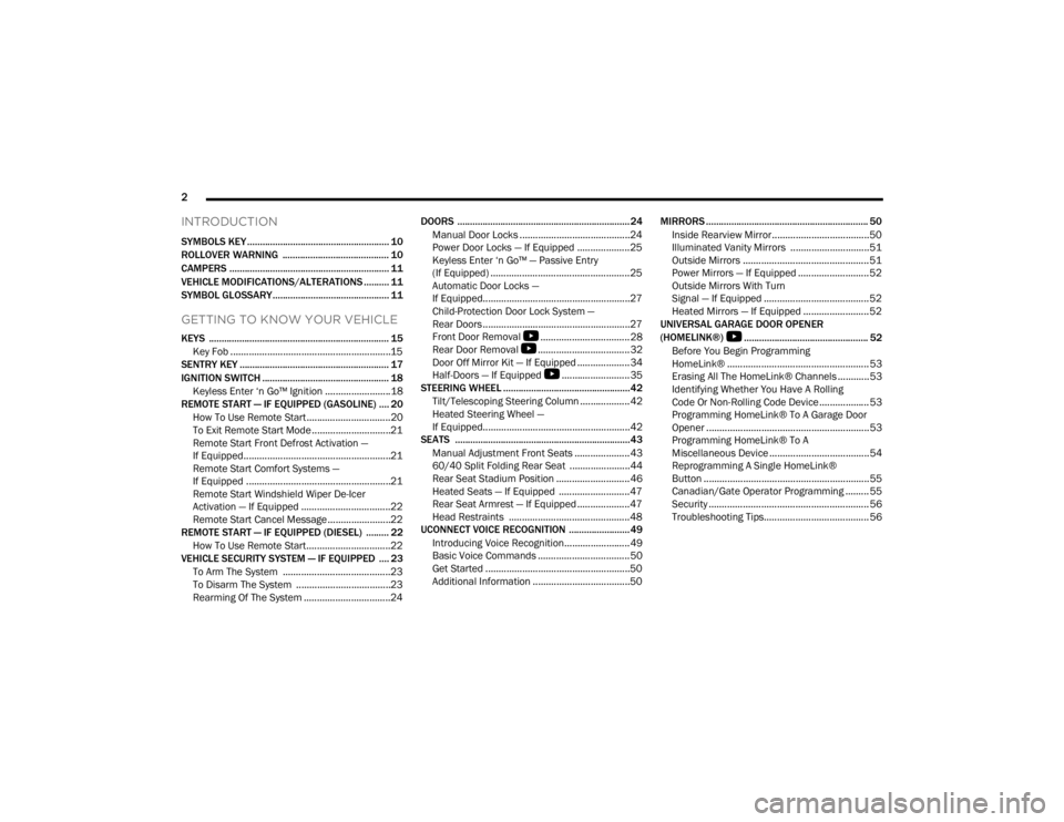
INTRODUCTION
SYMBOLS KEY ........................................................ 10
ROLLOVER WARNING .......................................... 10
CAMPERS ............................................................... 11
VEHICLE MODIFICATIONS/ALTERATIONS .......... 11
SYMBOL GLOSSARY.............................................. 11
GETTING TO KNOW YOUR VEHICLE
KEYS ....................................................................... 15
Key Fob .............................................................15
SENTRY KEY ........................................................... 17
IGNITION SWITCH .................................................. 18
Keyless Enter ‘n Go™ Ignition .........................18
REMOTE START — IF EQUIPPED (GASOLINE) .... 20
How To Use Remote Start ................................20
To Exit Remote Start Mode ..............................21
Remote Start Front Defrost Activation —
If Equipped........................................................21
Remote Start Comfort Systems —
If Equipped .......................................................21
Remote Start Windshield Wiper De-Icer
Activation — If Equipped ..................................22
Remote Start Cancel Message ........................22
REMOTE START — IF EQUIPPED (DIESEL) ......... 22
How To Use Remote Start ................................22
VEHICLE SECURITY SYSTEM — IF EQUIPPED .... 23
To Arm The System .........................................23
To Disarm The System ....................................23
Rearming Of The System .................................24 DOORS ....................................................................24
Manual Door Locks ..........................................24
Power Door Locks — If Equipped ....................25
Keyless Enter ‘n Go™ — Passive Entry
(If Equipped) .....................................................25
Automatic Door Locks —
If Equipped........................................................27
Child-Protection Door Lock System —
Rear Doors ........................................................27
Front Door Removal
S
..................................28
Rear Door Removal
S
...................................32
Door Off Mirror Kit — If Equipped ....................34
Half-Doors — If Equipped
S
..........................35
STEERING WHEEL ..................................................42
Tilt/Telescoping Steering Column ...................42
Heated Steering Wheel —
If Equipped........................................................42
SEATS .....................................................................43
Manual Adjustment Front Seats .....................43
60/40 Split Folding Rear Seat .......................44
Rear Seat Stadium Position ............................46
Heated Seats — If Equipped ...........................47
Rear Seat Armrest — If Equipped ....................47
Head Restraints ..............................................48
UCONNECT VOICE RECOGNITION ........................49
Introducing Voice Recognition.........................49
Basic Voice Commands ...................................50
Get Started .......................................................50
Additional Information .....................................50 MIRRORS ................................................................ 50
Inside Rearview Mirror..................................... 50
Illuminated Vanity Mirrors .............................. 51
Outside Mirrors ................................................ 51
Power Mirrors — If Equipped ........................... 52
Outside Mirrors With Turn
Signal — If Equipped ........................................ 52
Heated Mirrors — If Equipped ......................... 52
UNIVERSAL GARAGE DOOR OPENER
(HOMELINK®)
S
................................................. 52
Before You Begin Programming
HomeLink® ...................................................... 53
Erasing All The HomeLink® Channels ............ 53
Identifying Whether You Have A Rolling
Code Or Non-Rolling Code Device ................... 53
Programming HomeLink® To A Garage Door
Opener ..............................................................53
Programming HomeLink® To A
Miscellaneous Device ...................................... 54
Reprogramming A Single HomeLink®
Button ............................................................... 55
Canadian/Gate Operator Programming ......... 55
Security ............................................................. 56
Troubleshooting Tips........................................ 56
23_JT_OM_EN_USC_t.book Page 2
Page 6 of 448

4
INSTRUMENT CLUSTER DISPLAY ...................... 121 Instrument Cluster Display Location And
Controls .......................................................... 122
Oil Life Reset — If Equipped
S
................... 122
Off Road+ Display — If Equipped .................. 123
Instrument Cluster Display Selectable
Items .............................................................. 123
Instrument Cluster Display Menu Items ...... 124
Battery Saver On, Battery Saver Mode
Message, And Electrical Load Reduction
Actions
(If Equipped) .................................................. 127
Diesel Displays .............................................. 128 Diesel Particulate Filter (DPF) Messages .... 128Fuel System Messages ................................. 130
WARNING LIGHTS AND MESSAGES ................. 132
Red Warning Lights ....................................... 132
Yellow Warning Lights ................................... 135Yellow Indicator Lights .................................. 138
Green Indicator Lights................................... 139White Indicator Lights ................................... 140Blue Indicator Lights ..................................... 141
ONBOARD DIAGNOSTIC SYSTEM — OBD II ...... 141
Onboard Diagnostic System
(OBD II) Cybersecurity ................................... 142
EMISSIONS INSPECTION AND MAINTENANCE
PROGRAMS .......................................................... 142
STARTING AND OPERATING
STARTING THE ENGINE — GASOLINE ENGINE
(IF EQUIPPED) ...................................................... 144
Manual Transmission — If Equipped ........... 144Automatic Transmission —
If Equipped .................................................... 144
Normal Starting ............................................ 144
AutoPark ........................................................ 145Extreme Cold Weather
(Below –22°F Or −30°C) ............................ 146
Extended Park Starting ................................. 146
If Engine Fails To Start ................................. 147
After Starting ................................................. 147
STARTING THE ENGINE — DIESEL ENGINE
(IF EQUIPPED) ...................................................... 147
Automatic Transmission ............................... 148
Extreme Cold Weather .................................. 148
Normal Starting ............................................. 148Starting Fluids ............................................... 149
NORMAL OPERATION — DIESEL ENGINE ......... 149
Cold Weather Precautions ............................ 149
Engine Idling .................................................. 150
Stopping The Engine ..................................... 150
Cooling System Tips — Automatic
Transmission ................................................. 151
ENGINE BREAK-IN RECOMMENDATIONS —
GASOLINE ENGINE (IF EQUIPPED) ................... 151 ENGINE BREAK-IN RECOMMENDATIONS —
DIESEL ENGINE (IF EQUIPPED) .......................... 152
PARKING BRAKE ................................................. 152
MANUAL TRANSMISSION — IF EQUIPPED ....... 153
Shifting........................................................... 154
Downshifting.................................................. 155
AUTOMATIC TRANSMISSION —
IF EQUIPPED ......................................................... 155
Ignition Park Interlock................................... 156
Brake/Transmission Shift Interlock (BTSI)
System .......................................................... 1578–Speed Automatic Transmission .............. 157
Gear Ranges .................................................. 157
FOUR–WHEEL DRIVE OPERATION ................... 161
Four-Position Transfer Case —
If Equipped .................................................... 161
Five-Position Transfer Case —
If Equipped .................................................... 163
Trac-Lok Rear Axle — If Equipped ................ 165Axle Lock (Tru-Lok) Front And Rear —
If Equipped ................................................... 165
Axle Lock (Tru-Lok) Rear Only —
If Equipped ................................................... 166
Electronic Sway Bar Disconnect —
If Equipped ................................................... 166
OFF ROAD+ — If Equipped ............................ 168
ELECTRO-HYDRAULIC POWER STEERING ....... 168
23_JT_OM_EN_USC_t.book Page 4
Page 13 of 448
11
CAMPERS
This vehicle is NOT recommended for slide-in camper applications.
VEHICLE MODIFICATIONS/ALTERATIONS
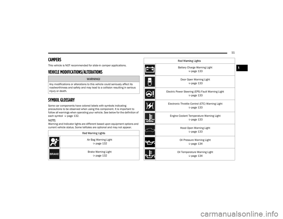
SYMBOL GLOSSARY
Some car components have colored labels with symbols indicating
precautions to be observed when using this component. It is important to
follow all warnings when operating your vehicle. See below for the definition of
each symbol Úpage 132.
NOTE:Warning and Indicator lights are different based upon equipment options and
current vehicle status. Some telltales are optional and may not appear.
WARNING!
Any modifications or alterations to this vehicle could seriously affect its
roadworthiness and safety and may lead to a collision resulting in serious
injury or death.
Red Warning LightsAir Bag Warning Light Úpage 132
Brake Warning Light Úpage 132
Battery Charge Warning Light
Úpage 133
Door Open Warning Light Úpage 133
Electric Power Steering (EPS) Fault Warning Light Úpage 133
Electronic Throttle Control (ETC) Warning Light Úpage 133
Engine Coolant Temperature Warning Light Úpage 133
Hood Open Warning Light Úpage 133
Oil Pressure Warning Light Úpage 134
Oil Temperature Warning Light Úpage 134
Red Warning Lights1
23_JT_OM_EN_USC_t.book Page 11
Page 80 of 448
78GETTING TO KNOW YOUR VEHICLE
(Continued)
POWER INVERTERS — IF EQUIPPED
There is a 115 V (400 W) maximum inverter outlet
located on the back of the center console to
convert Direct Current (DC) to Alternating Current
(AC).
This outlet can power cellular phones, electronics
and other low power devices requiring power up to
400 W. Certain video game consoles exceed this
power limit, as will most power tools.
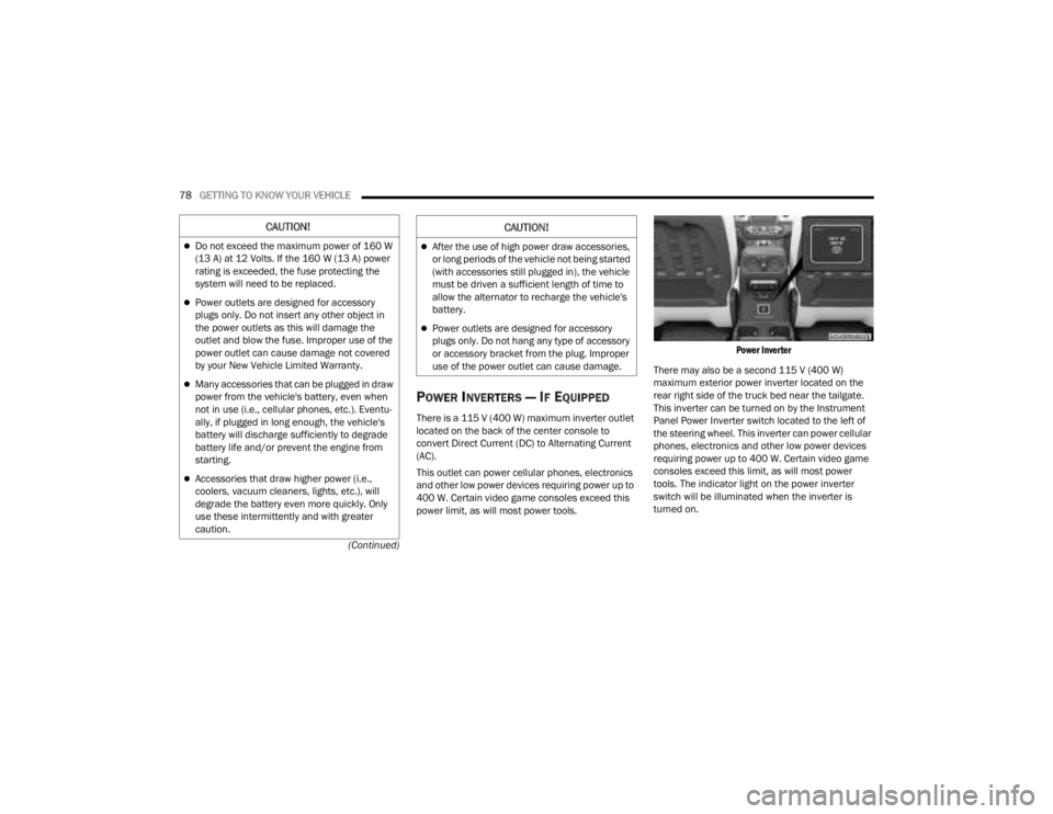
Power Inverter
There may also be a second 115 V (400 W)
maximum exterior power inverter located on the
rear right side of the truck bed near the tailgate.
This inverter can be turned on by the Instrument
Panel Power Inverter switch located to the left of
the steering wheel. This inverter can power cellular
phones, electronics and other low power devices
requiring power up to 400 W. Certain video game
consoles exceed this limit, as will most power
tools. The indicator light on the power inverter
switch will be illuminated when the inverter is
turned on.
CAUTION!
Do not exceed the maximum power of 160 W
(13 A) at 12 Volts. If the 160 W (13 A) power
rating is exceeded, the fuse protecting the
system will need to be replaced.
Power outlets are designed for accessory
plugs only. Do not insert any other object in
the power outlets as this will damage the
outlet and blow the fuse. Improper use of the
power outlet can cause damage not covered
by your New Vehicle Limited Warranty.
Many accessories that can be plugged in draw
power from the vehicle's battery, even when
not in use (i.e., cellular phones, etc.). Eventu -
ally, if plugged in long enough, the vehicle's
battery will discharge sufficiently to degrade
battery life and/or prevent the engine from
starting.
Accessories that draw higher power (i.e.,
coolers, vacuum cleaners, lights, etc.), will
degrade the battery even more quickly. Only
use these intermittently and with greater
caution.
After the use of high power draw accessories,
or long periods of the vehicle not being started
(with accessories still plugged in), the vehicle
must be driven a sufficient length of time to
allow the alternator to recharge the vehicle's
battery.
Power outlets are designed for accessory
plugs only. Do not hang any type of accessory
or accessory bracket from the plug. Improper
use of the power outlet can cause damage.
CAUTION!
23_JT_OM_EN_USC_t.book Page 78
Page 135 of 448
GETTING TO KNOW YOUR INSTRUMENT PANEL133
The light also will turn on when the parking brake
is applied with the ignition switch in the ON/RUN
position.
NOTE:This light shows only that the parking brake is
applied. It does not show the degree of brake appli -
cation.
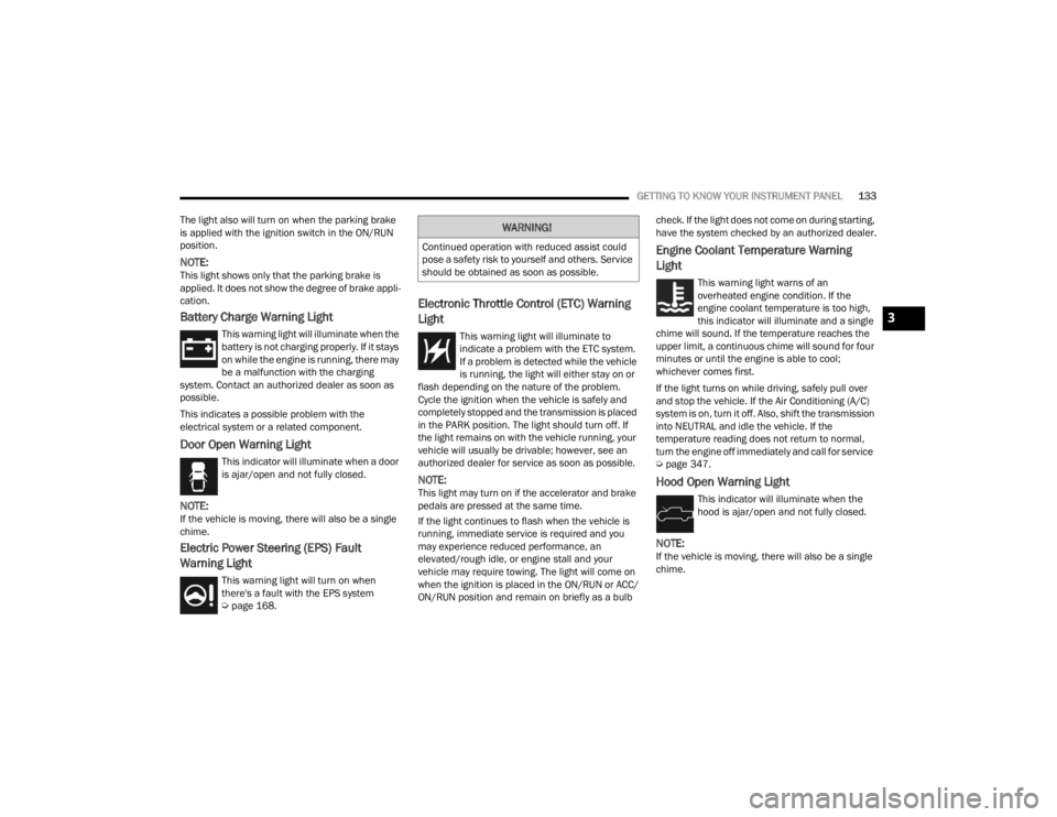
Battery Charge Warning Light
This warning light will illuminate when the
battery is not charging properly. If it stays
on while the engine is running, there may
be a malfunction with the charging
system. Contact an authorized dealer as soon as
possible.
This indicates a possible problem with the
electrical system or a related component.
Door Open Warning Light
This indicator will illuminate when a door
is ajar/open and not fully closed.
NOTE:If the vehicle is moving, there will also be a single
chime.
Electric Power Steering (EPS) Fault
Warning Light
This warning light will turn on when
there's a fault with the EPS system
Ú page 168.
Electronic Throttle Control (ETC) Warning
Light
This warning light will illuminate to
indicate a problem with the ETC system.
If a problem is detected while the vehicle
is running, the light will either stay on or
flash depending on the nature of the problem.
Cycle the ignition when the vehicle is safely and
completely stopped and the transmission is placed
in the PARK position. The light should turn off. If
the light remains on with the vehicle running, your
vehicle will usually be drivable; however, see an
authorized dealer for service as soon as possible.
NOTE:This light may turn on if the accelerator and brake
pedals are pressed at the same time.
If the light continues to flash when the vehicle is
running, immediate service is required and you
may experience reduced performance, an
elevated/rough idle, or engine stall and your
vehicle may require towing. The light will come on
when the ignition is placed in the ON/RUN or ACC/
ON/RUN position and remain on briefly as a bulb check. If the light does not come on during starting,
have the system checked by an authorized dealer.
Engine Coolant Temperature Warning
Light
This warning light warns of an
overheated engine condition. If the
engine coolant temperature is too high,
this indicator will illuminate and a single
chime will sound. If the temperature reaches the
upper limit, a continuous chime will sound for four
minutes or until the engine is able to cool;
whichever comes first.
If the light turns on while driving, safely pull over
and stop the vehicle. If the Air Conditioning (A/C)
system is on, turn it off. Also, shift the transmission
into NEUTRAL and idle the vehicle. If the
temperature reading does not return to normal,
turn the engine off immediately and call for service
Ú page 347.
Hood Open Warning Light
This indicator will illuminate when the
hood is ajar/open and not fully closed.
NOTE:If the vehicle is moving, there will also be a single
chime.
WARNING!
Continued operation with reduced assist could
pose a safety risk to yourself and others. Service
should be obtained as soon as possible.
3
23_JT_OM_EN_USC_t.book Page 133
Page 167 of 448
STARTING AND OPERATING165
completed, place the automatic transmission into
DRIVE or release the clutch pedal on a manual
transmission.
NOTE:Shifting into or out of 4L is possible with the vehicle
completely stopped; however, difficulty may occur
due to the mating teeth not being properly aligned.
Several attempts may be required for clutch teeth
alignment and shift completion to occur. The
preferred method is with the vehicle rolling at 1 to
3 mph (2 to 5 km/h). Avoid attempting to engage
or disengage 4L with the vehicle moving faster
than 1 to 3 mph (2 to 5 km/h).
During cold weather, you may experience
increased effort in shifting until the transfer case
fluid warms up. This is normal.
TRAC-LOK REAR AXLE — IF EQUIPPED
The Trac-Lok rear axle provides a constant driving
force to both rear wheels and reduces wheel spin
caused by the loss of traction at one driving wheel.
If traction differs between the two rear wheels, the
differential automatically proportions the usable
torque by providing more torque to the wheel that
has traction.
Trac-Lok is especially helpful during slippery
driving conditions. With both rear wheels on a
slippery surface, a slight application of the
accelerator will supply maximum traction.
AXLE LOCK (TRU-LOK) FRONT AND
R
EAR — IF EQUIPPED
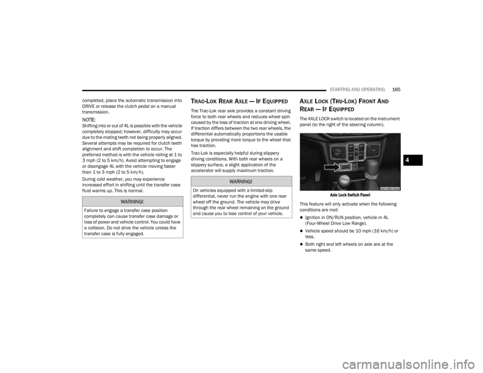
The AXLE LOCK switch is located on the instrument
panel (to the right of the steering column).
Axle Lock Switch Panel
This feature will only activate when the following
conditions are met:
Ignition in ON/RUN position, vehicle in 4L
(Four-Wheel Drive Low Range).
Vehicle speed should be 10 mph (16 km/h) or
less.
Both right and left wheels on axle are at the
same speed.
WARNING!
Failure to engage a transfer case position
completely can cause transfer case damage or
loss of power and vehicle control. You could have
a collision. Do not drive the vehicle unless the
transfer case is fully engaged.
WARNING!
On vehicles equipped with a limited-slip
differential, never run the engine with one rear
wheel off the ground. The vehicle may drive
through the rear wheel remaining on the ground
and cause you to lose control of your vehicle.
4
23_JT_OM_EN_USC_t.book Page 165
Page 170 of 448
168STARTING AND OPERATING
OFF ROAD+ — IF EQUIPPED
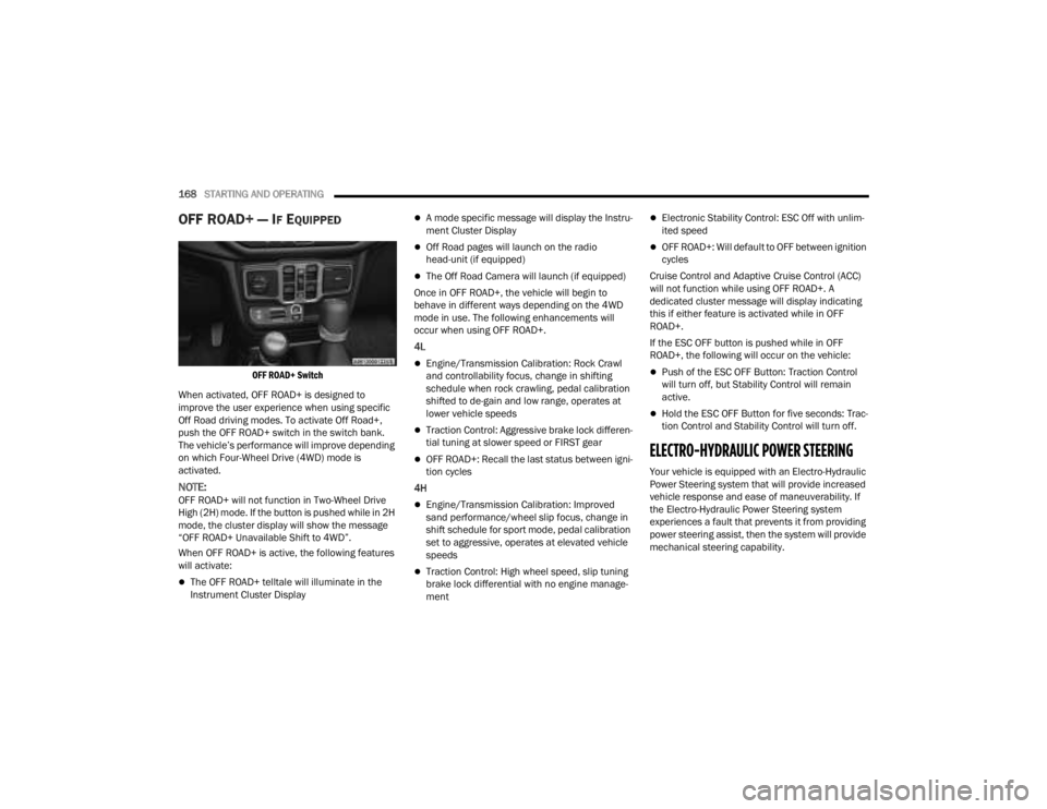
OFF ROAD+ Switch
When activated, OFF ROAD+ is designed to
improve the user experience when using specific
Off Road driving modes. To activate Off Road+,
push the OFF ROAD+ switch in the switch bank.
The vehicle’s performance will improve depending
on which Four-Wheel Drive (4WD) mode is
activated.
NOTE:OFF ROAD+ will not function in Two-Wheel Drive
High (2H) mode. If the button is pushed while in 2H
mode, the cluster display will show the message
“OFF ROAD+ Unavailable Shift to 4WD”.
When OFF ROAD+ is active, the following features
will activate:
The OFF ROAD+ telltale will illuminate in the
Instrument Cluster Display
A mode specific message will display the Instru -
ment Cluster Display
Off Road pages will launch on the radio
head-unit (if equipped)
The Off Road Camera will launch (if equipped)
Once in OFF ROAD+, the vehicle will begin to
behave in different ways depending on the 4WD
mode in use. The following enhancements will
occur when using OFF ROAD+.
4L
Engine/Transmission Calibration: Rock Crawl
and controllability focus, change in shifting
schedule when rock crawling, pedal calibration
shifted to de-gain and low range, operates at
lower vehicle speeds
Traction Control: Aggressive brake lock differen -
tial tuning at slower speed or FIRST gear
OFF ROAD+: Recall the last status between igni -
tion cycles
4H
Engine/Transmission Calibration: Improved
sand performance/wheel slip focus, change in
shift schedule for sport mode, pedal calibration
set to aggressive, operates at elevated vehicle
speeds
Traction Control: High wheel speed, slip tuning
brake lock differential with no engine manage -
ment
Electronic Stability Control: ESC Off with unlim -
ited speed
OFF ROAD+: Will default to OFF between ignition
cycles
Cruise Control and Adaptive Cruise Control (ACC)
will not function while using OFF ROAD+. A
dedicated cluster message will display indicating
this if either feature is activated while in OFF
ROAD+.
If the ESC OFF button is pushed while in OFF
ROAD+, the following will occur on the vehicle:
Push of the ESC OFF Button: Traction Control
will turn off, but Stability Control will remain
active.
Hold the ESC OFF Button for five seconds: Trac -
tion Control and Stability Control will turn off.
ELECTRO-HYDRAULIC POWER STEERING
Your vehicle is equipped with an Electro-Hydraulic
Power Steering system that will provide increased
vehicle response and ease of maneuverability. If
the Electro-Hydraulic Power Steering system
experiences a fault that prevents it from providing
power steering assist, then the system will provide
mechanical steering capability.
23_JT_OM_EN_USC_t.book Page 168
Page 171 of 448
STARTING AND OPERATING169
If the “SERVICE POWER STEERING”
message and a flashing icon are
displayed on the instrument cluster
screen, it indicates that the vehicle
needs to be taken to an authorized dealer for
service. It is likely the vehicle has lost power
steering assistance Ú page 121.
If the “POWER STEERING HOT” message and an
icon are displayed on the instrument cluster
screen, it indicates that extreme steering
maneuvers may have occurred, which caused an
over temperature condition in the power steering
system. You will lose power steering assistance
momentarily until the over temperature condition
no longer exists. Once driving conditions are safe,
pull over and let vehicle idle for a few moments
until the light turns off Ú page 121.
NOTE:
Even if power steering assistance is no longer
operational, it is still possible to steer the
vehicle. Under these conditions there will be a
substantial increase in steering effort, espe -cially at very low vehicle speeds and during
parking maneuvers.
If the condition persists, see an authorized
dealer for service.
STOP/START SYSTEM — AUTOMATIC
TRANSMISSION (IF EQUIPPED)
The Engine Stop/Start (ESS) function is developed
to reduce fuel consumption. The system will stop
the engine automatically during a vehicle stop if
the required conditions are met. Releasing the
brake pedal or pressing the accelerator pedal will
automatically restart the engine.
ESS vehicles have been upgraded with a
heavy-duty starter, enhanced battery, and other
upgraded engine parts, to handle the additional
engine starts.
NOTE:It is recommended that the Stop/Start system be
disabled during off-road use.
Secondary Battery
Your vehicle may be equipped with a secondary
battery used to power the Stop/Start system and
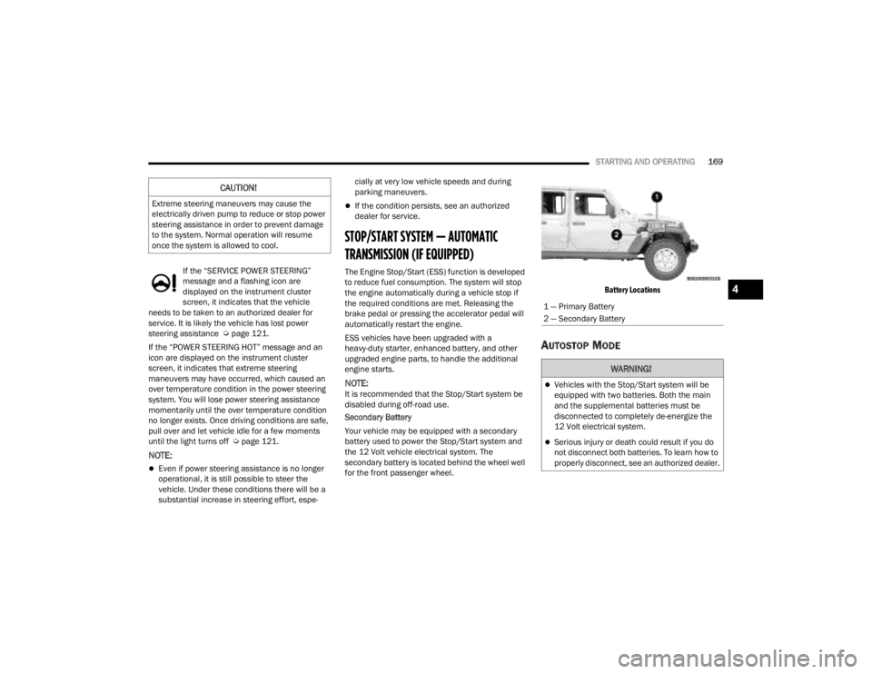
the 12 Volt vehicle electrical system. The
secondary battery is located behind the wheel well
for the front passenger wheel.
Battery Locations
AUTOSTOP MODE
CAUTION!
Extreme steering maneuvers may cause the
electrically driven pump to reduce or stop power
steering assistance in order to prevent damage
to the system. Normal operation will resume
once the system is allowed to cool.
1 — Primary Battery
2 — Secondary Battery
WARNING!
Vehicles with the Stop/Start system will be
equipped with two batteries. Both the main
and the supplemental batteries must be
disconnected to completely de-energize the
12 Volt electrical system.
Serious injury or death could result if you do
not disconnect both batteries. To learn how to
properly disconnect, see an authorized dealer.
4
23_JT_OM_EN_USC_t.book Page 169
Page 210 of 448
208STARTING AND OPERATING
3. After all bolts and nuts have been removed, pull the side step assembly off of the vehicle.
4. To reinstall the side steps align the studs to the body side holes and fasten all nuts on all four
brackets. Then secure all four bolts to the
underbody. Repeat the reassembly procedure
for the other side.
Bumper End Cap Removal — If Equipped
The end caps on your vehicle’s front bumper can
be removed by following the steps below:
NOTE:Bumper end caps are removable on steel bumpers
only.
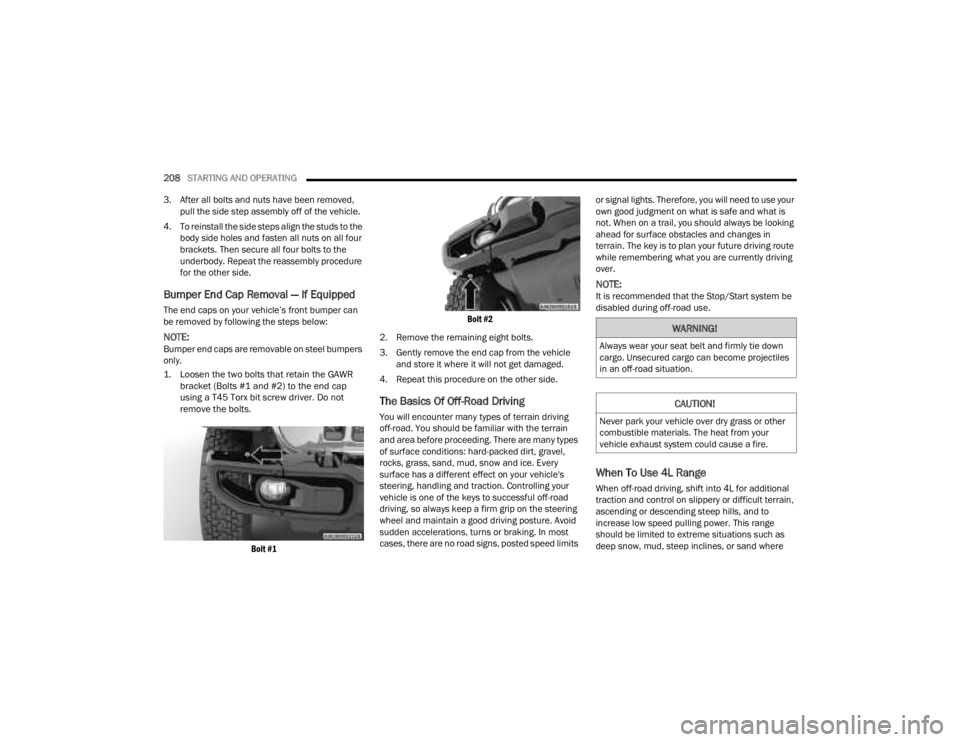
1. Loosen the two bolts that retain the GAWR bracket (Bolts #1 and #2) to the end cap
using a T45 Torx bit screw driver. Do not
remove the bolts.
Bolt #1 Bolt #2
2. Remove the remaining eight bolts.
3. Gently remove the end cap from the vehicle and store it where it will not get damaged.
4. Repeat this procedure on the other side.
The Basics Of Off-Road Driving
You will encounter many types of terrain driving
off-road. You should be familiar with the terrain
and area before proceeding. There are many types
of surface conditions: hard-packed dirt, gravel,
rocks, grass, sand, mud, snow and ice. Every
surface has a different effect on your vehicle's
steering, handling and traction. Controlling your
vehicle is one of the keys to successful off-road
driving, so always keep a firm grip on the steering
wheel and maintain a good driving posture. Avoid
sudden accelerations, turns or braking. In most
cases, there are no road signs, posted speed limits or signal lights. Therefore, you will need to use your
own good judgment on what is safe and what is
not. When on a trail, you should always be looking
ahead for surface obstacles and changes in
terrain. The key is to plan your future driving route
while remembering what you are currently driving
over.
NOTE:It is recommended that the Stop/Start system be
disabled during off-road use.
When To Use 4L Range
When off-road driving, shift into 4L for additional
traction and control on slippery or difficult terrain,
ascending or descending steep hills, and to
increase low speed pulling power. This range
should be limited to extreme situations such as
deep snow, mud, steep inclines, or sand where
WARNING!
Always wear your seat belt and firmly tie down
cargo. Unsecured cargo can become projectiles
in an off-road situation.
CAUTION!
Never park your vehicle over dry grass or other
combustible materials. The heat from your
vehicle exhaust system could cause a fire.
23_JT_OM_EN_USC_t.book Page 208
Page 211 of 448
STARTING AND OPERATING209
additional low speed pulling power is needed.
Vehicle speeds in excess of 25 mph (40 km/h)
should be avoided when in 4L range.
Simultaneous Brake And Throttle
Operation
Many off-road driving conditions require the
simultaneous use of the brake and throttle
(two-footed driving). When climbing rocks, logs, or
other stepped objects, using light brake pressure
with light throttle will keep the vehicle from jerking
or lurching. This technique is also used when you
need to stop and restart a vehicle on a steep
incline.
Driving In Snow, Mud And Sand
SNOW
In heavy snow or for additional control and traction
at slower speeds, shift the transmission into a low
gear and the transfer case into 4L if necessary. Do
not shift to a lower gear than necessary to maintain
headway. Over-revving the engine can spin the
wheels and traction will be lost. If you start to slow
to a stop, try turning your steering wheel no more than a quarter turn quickly back and forth, while
still applying throttle. This will allow the tires to get
fresh traction and help maintain your momentum.
MUD
Deep mud creates a great deal of suction around
the tires and is very difficult to get through. You
should use DRIVE, with the transfer case in the 4L
position to maintain your momentum. If you start to
slow to a stop, try turning your steering wheel no
more than a quarter turn quickly back and forth for
additional traction. Mud holes pose an increased
threat of vehicle damage and getting stuck. They
are normally full of debris from previous vehicles
getting stuck. As a good practice before entering
any mud hole, get out and determine how deep it
is, if there are any hidden obstacles and if the
vehicle can be safely recovered if stuck.
SAND
Soft sand is very difficult to travel through with full
tire pressure. When crossing soft, sandy spots in a
trail, maintain your vehicle's momentum and do
not stop. The key to driving in soft sand is using the
appropriate tire pressure, accelerating slowly, avoiding abrupt maneuvers and maintaining the
vehicle's momentum. If you are going to be driving
on large soft sandy areas or dunes, reduce your
tire pressure to a minimum of 15 psi (103 kPa) to
allow for a greater tire surface area. Reduced tire
pressure will drastically improve your traction and
handling while driving on the soft sand, but you
must return the tires to normal air pressure before
driving on pavement or other hard surfaces. Be
sure you have a way to reinflate the tires prior to
reducing the pressure.
Crossing Obstacles (Rocks And Other High
Points)
While driving off-road, you will encounter many
types of terrain. These varying types of terrain bring
different types of obstacles. Before proceeding,
review the path ahead to determine the correct
approach and your ability to safely recover the
vehicle if something goes wrong. Keeping a firm
grip on the steering wheel, bring the vehicle to a
complete stop and then inch the vehicle forward
CAUTION!
Do not use 4L range when operating the vehicle
on dry pavement. Driveline hardware damage
can result.
CAUTION!
On icy or slippery roads, do not downshift at high
engine RPM or vehicle speeds, because engine
braking may cause skidding and loss of control.
CAUTION!
Reduced tire pressures may cause tire
unseating and total loss of air pressure. To
reduce the risk of tire unseating, while at a
reduced tire pressure, reduce your speed and
avoid sharp turns or abrupt maneuvers.
4
23_JT_OM_EN_USC_t.book Page 209