warning JEEP GLADIATOR 2023 Owner's Guide
[x] Cancel search | Manufacturer: JEEP, Model Year: 2023, Model line: GLADIATOR, Model: JEEP GLADIATOR 2023Pages: 448, PDF Size: 17.37 MB
Page 50 of 448
48GETTING TO KNOW YOUR VEHICLE
HEAD RESTRAINTS
Head restraints are designed to reduce the risk of
injury by restricting head movement in the event of
a rear impact. Head restraints should be adjusted
so that the top of the head restraint is located
above the top of your ear.
Front Head Restraints
To raise the head restraint, pull upward on the
head restraint. To lower the head restraint, push
the adjustment button located on the base of the
head restraint, and push downward on the head
restraint. The release button does not need to be
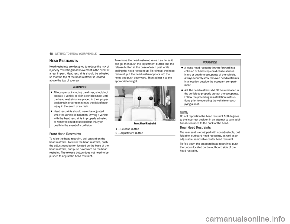
pushed to adjust the head restraint. To remove the head restraint, raise it as far as it
can go, then push the adjustment button and the
release button at the base of each post while
pulling the head restraint up. To reinstall the head
restraint, put the head restraint posts into the
holes and push downward. Then adjust it to the
appropriate height.
Front Head Restraint
NOTE:Do not reposition the head restraint 180 degrees
to the incorrect position in an attempt to gain addi -
tional clearance to the back of the head.
Rear Head Restraints
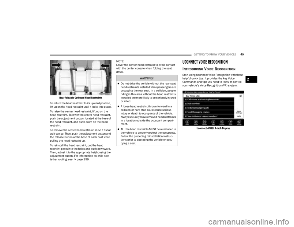
The rear seat is equipped with nonadjustable, but
foldable, outboard head restraints, as well as an
adjustable, removable center head restraint.
To fold down the outboard head restraints, push
the button located on the outboard side of the
head restraint.
WARNING!
All occupants, including the driver, should not
operate a vehicle or sit in a vehicle’s seat until
the head restraints are placed in their proper
positions in order to minimize the risk of neck
injury in the event of a crash.
Head restraints should never be adjusted
while the vehicle is in motion. Driving a vehicle
with the head restraints improperly adjusted
or removed could cause serious injury or
death in the event of a collision.
1 — Release Button
2 — Adjustment Button
WARNING!
A loose head restraint thrown forward in a
collision or hard stop could cause serious
injury or death to occupants of the vehicle.
Always securely stow removed head restraints
in a location outside the occupant compart -
ment.
ALL the head restraints MUST be reinstalled in
the vehicle to properly protect the occupants.
Follow the preceding reinstallation instruc -
tions prior to operating the vehicle or occu -
pying a seat.
23_JT_OM_EN_USC_t.book Page 48
Page 51 of 448
GETTING TO KNOW YOUR VEHICLE49
Rear Foldable Outboard Head Restraints
To return the head restraint to its upward position,
lift up on the head restraint until it locks into place.
To raise the center head restraint, lift up on the
head restraint. To lower the center head restraint,
push the adjustment button, located at the base of
the head restraint, and push down on the head
restraint.
To remove the center head restraint, raise it as far
as it can go. Then, push the adjustment button and
the release button at the base of each post while
pulling the head restraint up.
To reinstall the head restraint, put the head
restraint posts into the holes and push downward.
Then, adjust it to the appropriate height using the
adjustment button. For information on child seat
tether routing, see Ú page 299.
NOTE:Lower the center head restraint to avoid contact
with the center console when folding the seat
down.UCONNECT VOICE RECOGNITION
INTRODUCING VOICE RECOGNITION
Start using Uconnect Voice Recognition with these
helpful quick tips. It provides the key Voice
Commands and tips you need to know to control
your vehicle’s Voice Recognition (VR) system.
Uconnect 4 With 7-inch Display
WARNING!
Do not drive the vehicle without the rear seat
head restraints installed while passengers are
occupying the rear seat. In a collision, people
riding in this area without the head restraints
installed are more likely to be seriously injured
or killed.
A loose head restraint thrown forward in a
collision or hard stop could cause serious
injury or death to occupants of the vehicle.
Always securely stow removed head restraints
in a location outside the occupant compart -
ment.
ALL the head restraints MUST be reinstalled in
the vehicle to properly protect the occupants.
Follow the preceding reinstallation instruc -
tions prior to operating the vehicle or occu -
pying a seat.
2
23_JT_OM_EN_USC_t.book Page 49
Page 54 of 448
52GETTING TO KNOW YOUR VEHICLE
POWER MIRRORS — IF EQUIPPED
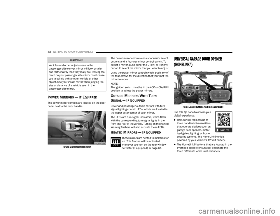
The power mirror controls are located on the door
panel next to the door handle.
Power Mirror Control Switch
The power mirror controls consist of mirror select
buttons and a four-way mirror control switch. To
adjust a mirror, push either the L (left) or R (right)
button to select the mirror that you want to adjust.
Using the power mirror control switch, push any of
the four arrows for the direction that you want the
mirror to move.
NOTE:The ignition switch must be in the ACC or ON/RUN
position to adjust the power mirrors.
OUTSIDE MIRRORS WITH TURN
SIGNAL — IF EQUIPPED
Driver and passenger outside mirrors with turn
signal lighting contain LEDs, which are located in
the upper outer corner of each mirror.
The LEDs are turn signal indicators, which flash
with the corresponding turn signal lights in the
front and rear of the vehicle. Turning on the Hazard
Warning flashers will also activate these LEDs.
HEATED MIRRORS — IF EQUIPPED
These mirrors are heated to melt frost or
ice. This feature will be activated
whenever you turn on the rear window
defroster (if equipped) Ú
page 61.
UNIVERSAL GARAGE DOOR OPENER
(HOMELINK®)
HomeLink® Buttons And Indicator Light
Use this QR code to access your
digital experience.
HomeLink® replaces up to
three hand-held transmitters
that operate devices such as
garage door openers, motor -
ized gates, lighting, or home
security systems. The HomeLink® unit is
powered by your vehicle’s 12 Volt battery.
The HomeLink® buttons that are located in the
overhead console or sunvisor designate the
three different HomeLink® channels.
WARNING!
Vehicles and other objects seen in the
passenger side convex mirror will look smaller
and farther away than they really are. Relying too
much on your passenger side mirror could cause
you to collide with another vehicle or other
object. Use your inside mirror when judging the
size or distance of a vehicle seen in the
passenger side mirror.
23_JT_OM_EN_USC_t.book Page 52
Page 56 of 448
54GETTING TO KNOW YOUR VEHICLE
(Continued)
3. Push and hold the HomeLink® button you
want to program while you push and hold the
garage door opener transmitter button you are
trying to replicate.
4. Continue to hold both buttons and observe the HomeLink® indicator light. The HomeLink®
indicator light will flash slowly and then rapidly.
Once this happens, release both buttons.
NOTE:Make sure the garage door opener motor is
plugged in before moving on to the rolling code/
non-rolling code final steps.
Rolling Code Garage Door Opener Final Steps
NOTE:You have 30 seconds in which to initiate rolling
code final step 2, after completing rolling code
final step 1.
1. At the garage door opener motor (in the garage), locate the “LEARN” or “TRAIN”
button. This can usually be found where the
hanging antenna wire is attached to the
garage door opener motor. Firmly push and
release the “LEARN” or “TRAIN” button.
2. Return to the vehicle and push the programmed HomeLink® button three times
(holding the button for two seconds each
time). If the garage door opener motor
operates, programming is complete. 3. Push the programmed HomeLink® button to
confirm that the garage door opener motor
operates. If the garage door opener motor
does not operate, repeat the final steps for the
rolling code procedure.
Non-Rolling Code Garage Door Opener Final Steps
1. Push and hold the programmed HomeLink® button and observe the HomeLink® indicator
light. If the HomeLink® indicator light stays
on constantly, programming is complete.
2. Push the programmed HomeLink® button to confirm that the garage door opener motor
operates. If the garage door opener motor
does not operate, repeat the steps from the
beginning.
PROGRAMMING HOMELINK® TO A
M
ISCELLANEOUS DEVICE
The procedure on how to program HomeLink® to a
miscellaneous device follows the same procedure
as programming to a garage door opener
Ú page 53. Be sure to determine if the device has
a rolling code, or non-rolling code before beginning
the programming process.
NOTE:Canadian radio frequency laws require transmitter
signals to time-out (or quit) after several seconds
of transmission, which may not be long enough for
HomeLink® to pick up the signal during
programming. Similar to this Canadian law, some
U.S. gate operators are designed to time-out in the
same manner. The procedure may need to be
performed multiple times to successfully pair the
device to your HomeLink® buttons.
WARNING!
Your motorized door or gate will open and
close while you are programming the universal
transceiver. Do not program the transceiver if
people or pets are in the path of the door or
gate.
Do not run your vehicle in a closed garage or
confined area while programming the trans -
ceiver. Exhaust gas from your vehicle contains
carbon monoxide which is odorless and color -
less. Carbon monoxide is poisonous when
inhaled and can cause you and others to be
severely injured or killed.
WARNING!
23_JT_OM_EN_USC_t.book Page 54
Page 58 of 448
56GETTING TO KNOW YOUR VEHICLE
SECURITY
It is advised to erase all channels before you sell or
turn in your vehicle.
To do this, push and hold the two outside buttons
for 20 seconds until the indicator flashes. Note
that all channels will be erased. Individual
channels cannot be erased.
The HomeLink® Universal Transceiver is disabled
when the Vehicle Security system is active.
NOTE:The universal garage door opener only operates
when the engine is running for security reasons
associated with removable tops and doors.
TROUBLESHOOTING TIPS
If you are having trouble programming
HomeLink®, here are some of the most common
solutions:
Replace the battery in the garage door opener
hand-held transmitter.
Push the LEARN button on the garage door
opener to complete the training for a rolling code.
Did you unplug the device for programming and
remember to plug it back in? If you have any problems, or require assistance,
please call toll-free 1-800-355-3515 or, on the
Internet at HomeLink.com for information or
assistance.
EXTERIOR LIGHTS
HEADLIGHT SWITCH
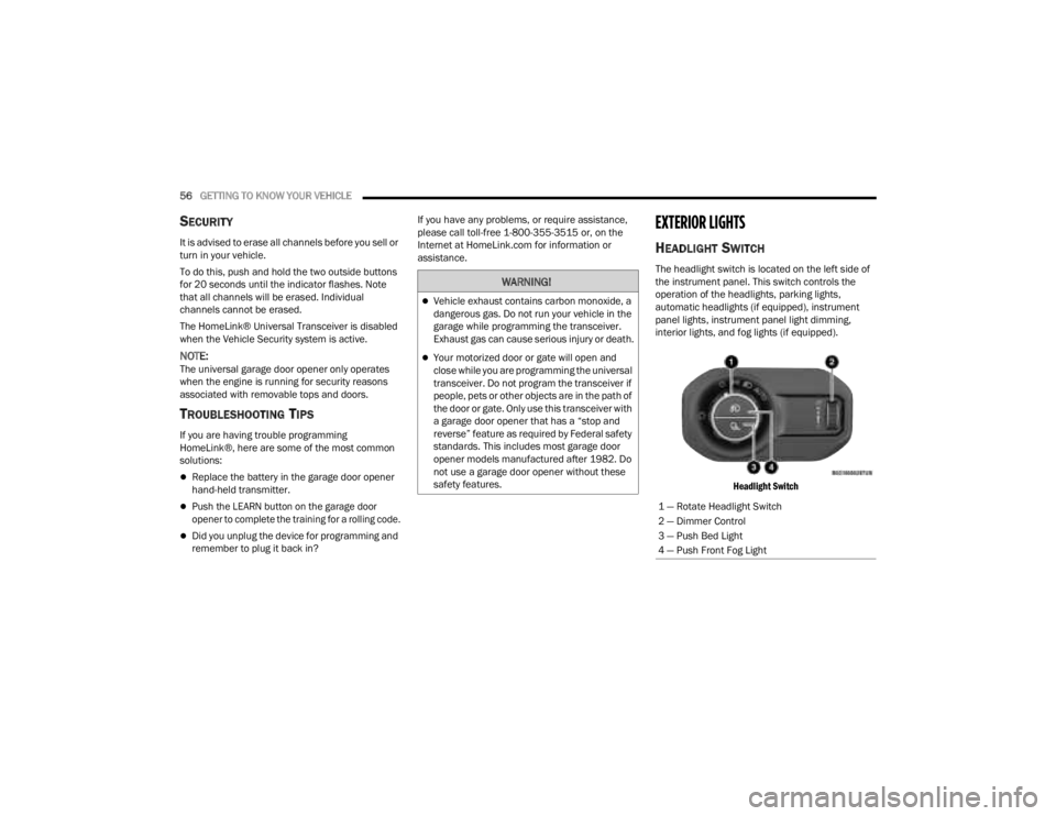
The headlight switch is located on the left side of
the instrument panel. This switch controls the
operation of the headlights, parking lights,
automatic headlights (if equipped), instrument
panel lights, instrument panel light dimming,
interior lights, and fog lights (if equipped).
Headlight Switch
WARNING!
Vehicle exhaust contains carbon monoxide, a
dangerous gas. Do not run your vehicle in the
garage while programming the transceiver.
Exhaust gas can cause serious injury or death.
Your motorized door or gate will open and
close while you are programming the universal
transceiver. Do not program the transceiver if
people, pets or other objects are in the path of
the door or gate. Only use this transceiver with
a garage door opener that has a “stop and
reverse” feature as required by Federal safety
standards. This includes most garage door
opener models manufactured after 1982. Do
not use a garage door opener without these
safety features.
1 — Rotate Headlight Switch
2 — Dimmer Control
3 — Push Bed Light
4 — Push Front Fog Light
23_JT_OM_EN_USC_t.book Page 56
Page 59 of 448
GETTING TO KNOW YOUR VEHICLE57
Headlight Switch (Vehicles Sold In Canada)
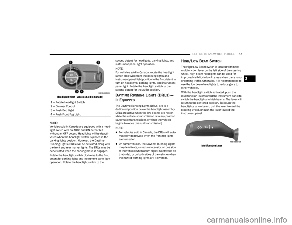
NOTE:Vehicles sold in Canada are equipped with a head -
light switch with an AUTO and ON detent but
without an OFF detent. Headlights will be deacti -
vated when the headlight switch is placed in the
parking lights position. However, the Daytime
Running Lights (DRLs) will be activated along with
the front and rear marker lights. The DRLs may be
deactivated when the parking brake is engaged.
Rotate the headlight switch clockwise to the first
detent for parking lights and instrument panel light
operation. Rotate the headlight switch to the second detent for headlights, parking lights, and
instrument panel light operation.
NOTE:For vehicles sold in Canada, rotate the headlight
switch clockwise from the parking lights and
instrument panel light position to the first detent to
turn on headlights, parking lights, and instrument
panel light. Rotate the headlight switch to the
second detent for the AUTO position.
DAYTIME RUNNING LIGHTS (DRLS) —
I
F EQUIPPED
The Daytime Running Lights (DRLs) are in a
dedicated position below the headlight assembly.
DRLs are active when the low beams are not on
while the vehicle’s transmission is in any position
(automatic transmission), or when the vehicle
begins to move (manual transmission).
NOTE:
For vehicles sold in Canada, the DRLs will auto -
matically deactivate when the front fog lights
are turned on.
On some vehicles, the Daytime Running Lights
may deactivate, or reduce intensity, on one side
of the vehicle (when a turn signal is activated on
that side), or on both sides of the vehicle (when
the hazard warning lights are activated).
HIGH/LOW BEAM SWITCH
The High/Low Beam switch is located within the
multifunction lever on the left side of the steering
wheel. High beam headlights can be used for
improved visibility in low lit areas when there is no
oncoming traffic. Otherwise, it is recommended to
use the low beam headlights to reduce glare to
other vehicles.
With the headlight switch activated, push the
multifunction lever toward the instrument panel to
switch the headlights to high beams. The lever will
return to the centered position. To return the
headlights to low beam, pull the lever toward the
steering wheel, or push the lever toward the
instrument panel.
Multifunction Lever
1 — Rotate Headlight Switch
2 — Dimmer Control
3 — Push Bed Light
4 — Push Front Fog Light
2
23_JT_OM_EN_USC_t.book Page 57
Page 63 of 448
GETTING TO KNOW YOUR VEHICLE61
Rotate the end of the lever upward to the first
detent past the intermittent settings for low-speed
wiper operation. Rotate the end of the lever
upward to the second detent past the intermittent
settings for high-speed wiper operation.
Intermittent Wipers
Use the intermittent wiper when weather
conditions make a single wiping cycle, with a
variable pause between cycles, desirable. Rotate
the end of the lever to the first detent position for
one of four intermittent settings. The delay cycle
can be set anywhere between 1 to 18 seconds.
NOTE:The wiper delay times depend on vehicle speed. If
the vehicle is moving less than 10 mph (16 km/h),
delay times will be doubled. Windshield Washers
To use the washer, pull the lever toward you and
hold until desired spray is reached. If the lever is
pulled while in the delay range, the wiper will start
and continue to operate for two or three wipe
cycles after the lever is released. Then, the
intermittent interval previously selected will
resume.
If the lever is pulled while in the off position, the
wipers will operate for two or three wipe cycles.
Then, the wipers will turn off.
NOTE:As a protective measure, the washer will stop if the
switch is held for more than 20 seconds. Once the
switch is released the washer will resume normal
operation.
Mist
Push upward on the wiper lever to activate a single
wipe to clear off-road mist or spray from a passing
vehicle. As long as the lever is held up, the wipers
will continue to operate.
NOTE:The mist feature does not activate the washer
pump; therefore, no washer fluid will be sprayed on
the windshield. The washer function must be used
in order to spray the windshield with washer fluid.
For information on wiper care and replacement,
see Ú
page 374.
CLIMATE CONTROLS
The Climate Control system allows you to regulate
the temperature, air flow, and direction of air
circulating throughout the vehicle. The controls are
located on the touchscreen and on the instrument
panel below the radio.
CAUTION!
In cold weather, always turn off the wiper switch
and allow the wipers to return to the park
position before turning off the engine. If the
wiper switch is left on and the wipers freeze to
the windshield, damage to the wiper motor may
occur when the vehicle is restarted.
WARNING!
Sudden loss of visibility through the windshield
could lead to a collision. You might not see other
vehicles or other obstacles. To avoid sudden
icing of the windshield during freezing weather,
warm the windshield with the defroster before
and during windshield washer use.
2
23_JT_OM_EN_USC_t.book Page 61
Page 70 of 448
68GETTING TO KNOW YOUR VEHICLE
Window Fogging
Vehicle windows tend to fog on the inside in mild,
rainy, and/or humid weather. To clear the
windows, select Defrost or Mix mode and increase
the front blower speed. Do not use the
Recirculation mode without A/C for long periods,
as fogging may occur.
Outside Air Intake
Make sure the air intake, located directly in front of
the windshield, is free of obstructions, such as
leaves. Leaves collected in the air intake may
reduce airflow, and if they enter the air distribution
box, they could plug the water drains. In Winter
months, make sure the air intake is clear of ice,
slush, and snow.
Cabin Air Filter
The Climate Control system filters out dust and
pollen from the air. Contact an authorized dealer to
service your cabin air filter, and to have it replaced
when needed.
Stop/Start System — If Equipped
While in an Autostop, the Climate Control system
may automatically adjust airflow to maintain cabin
comfort. Customer settings will be maintained
upon return to an engine running condition.
Operating Tips ChartINTERIOR STORAGE AND EQUIPMENT
STORAGE
Glove Compartment
The glove compartment is located on the
passenger side of the instrument panel.
To open the glove compartment, pull the release
handle.
Glove Compartment Release Handle
WEATHER CONTROL SETTINGS
Hot Weather And
Vehicle Interior Is Very
Hot Set the mode control to
(Panel Mode),
(MAX A/C) on, and
blower on high. Roll
down the windows for a
minute to flush out the
hot air. Adjust the
controls as needed to
achieve comfort.
Warm Weather Turn (A/C) on and
set the mode control to
(Panel Mode).
Cool Sunny Operate in (Bi-Level
Mode).
Cool & Humid
Conditions Set the mode control to
(Mix Mode) and
turn on (A/C) to
keep windows clear.
Cold Weather Set the mode control to
(Floor Mode). If
windshield fogging
starts to occur, move
the control to (Mix
Mode).
WARNING!
Do not operate this vehicle with the glove
compartment in the open position. Driving with
the glove compartment open may result in injury
in a collision.
23_JT_OM_EN_USC_t.book Page 68
Page 74 of 448
72GETTING TO KNOW YOUR VEHICLE
Depending on your vehicle’s specifications, the USB
port may contain playback capabilities and will allow
you to play music from your smartphone device or
USB devices through your vehicle’s sound system.
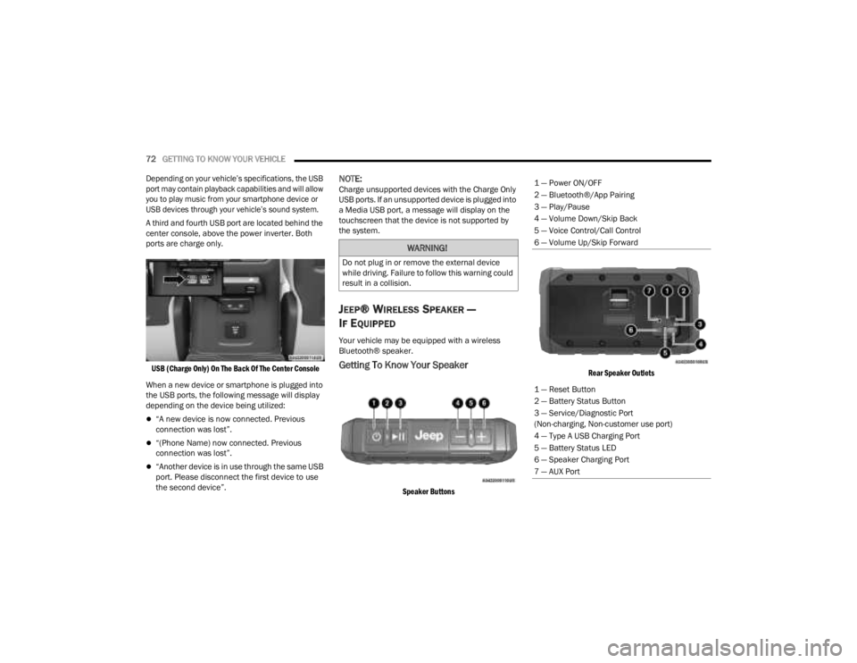
A third and fourth USB port are located behind the
center console, above the power inverter. Both
ports are charge only.
USB (Charge Only) On The Back Of The Center Console
When a new device or smartphone is plugged into
the USB ports, the following message will display
depending on the device being utilized:
“A new device is now connected. Previous
connection was lost”.
“(Phone Name) now connected. Previous
connection was lost”.
“Another device is in use through the same USB
port. Please disconnect the first device to use
the second device”.
NOTE:Charge unsupported devices with the Charge Only
USB ports. If an unsupported device is plugged into
a Media USB port, a message will display on the
touchscreen that the device is not supported by
the system.
JEEP® WIRELESS SPEAKER —
I
F EQUIPPED
Your vehicle may be equipped with a wireless
Bluetooth® speaker.
Getting To Know Your Speaker
Speaker Buttons Rear Speaker Outlets
WARNING!
Do not plug in or remove the external device
while driving. Failure to follow this warning could
result in a collision.
1 — Power ON/OFF
2 — Bluetooth®/App Pairing
3 — Play/Pause
4 — Volume Down/Skip Back
5 — Voice Control/Call Control
6 — Volume Up/Skip Forward
1 — Reset Button
2 — Battery Status Button
3 — Service/Diagnostic Port
(Non-charging, Non-customer use port)
4 — Type A USB Charging Port
5 — Battery Status LED
6 — Speaker Charging Port
7 — AUX Port
23_JT_OM_EN_USC_t.book Page 72
Page 78 of 448
76GETTING TO KNOW YOUR VEHICLE
Waterproof Features
The Jeep® wireless speaker is IP67 waterproof
certified with design in mind to withstand rainfall,
waterjets, splashing and being submerged in up to
3 ft (1 m) of water for up to 30 minutes.
Warnings, Caution & Legal Information
To reduce the risk of fire or electric shock, do not
expose the Jeep® wireless speaker to rain or
moisture while charging. The Jeep® wireless
speaker should not be exposed to dripping or
splashing, and objects filled with liquids, such as
vases, should not be placed on or near it while
being charged or charging other devices. As with
any electronic products, use care not to spill liquids
into any part of the product. Liquids can cause a
failure and/or a fire hazard. The power supply must
be used indoors only. Make no modifications to the
product or accessories. Unauthorized alterations
may compromise safety, regulatory compliance,
and system performance, and will void the
warranty. Do not place any flame sources, such as
lighted candles, on or near the Jeep® wireless speaker. The Jeep® wireless speaker contains
small parts that may be a choking hazard and is
not suitable for children under age 3. Do not
continue charging the battery if it does not reach
full charge within the specified charging time.
Overcharging may cause the battery to become
hot, rupture, or ignite. If you see any heat
deformation or leakage, properly dispose of the
battery. Do not attempt to charge the battery in
temperatures outside the range of 32°- 104°F
(0° - 40°C). If the battery begins to leak, do not
allow the liquid to come in contact with your skin or
eyes. If contact has been made, wash the affected
area with plenty of water and seek medical
attention immediately. Do not expose the Jeep®
wireless speaker or battery to excessive heat,
including direct sunlight or fire. Do not store or use
inside cars in hot weather, where it can be exposed
to temperatures in excess of 115°F (60°C). Doing
so may cause the battery and power supply to
generate heat, rupture, or ignite. Using the Jeep®
wireless speaker in this manner also may result in
a loss of performance and a shortened life
expectancy. Extended exposure to direct sunlight
may damage the external appearance and
material qualities. Do not step on, throw, or drop
batteries or the power supply or device, or expose
them to a strong shock. Do not pierce, crush, dent,
or deform the batteries or power supply in any way.
If either becomes deformed, properly dispose of it.
Do not short-circuit batteries. Do not attempt to service the Jeep® wireless speaker yourself.
Opening or removing covers may expose you to
dangerous voltages or other hazards and will void
the manufacturer’s warranty. To prevent risk of fire
or electric shock, avoid overloading wall outlets,
extension cords, or integral convenience
receptacles. Your Bluetooth® device (mobile
phone, music player, tablet, laptop, etc.) must
support the A2DP Bluetooth® profile in order to
work wirelessly with your Jeep® wireless speaker.
The A2DP profile is supported by most recent
mobile products with built-in Bluetooth®
capability. Please refer to your device’s user
manual for details and instruction regarding the
Bluetooth® profiles it supports. This device
complies with part 15 of the FCC Rules. Operation
is subject to the following two conditions: (1) This
device may not cause harmful interference, and
(2) this device must accept any interference
received, including interference that may cause
undesired operation.
Jeep® follows Safety Instruction for CE- LV. Do not
operate products in temperatures outside the
range of -5 to 40°C. Operating Frequency Band:
2402 MHz to 2480 MHz. Maximum RF power:
6 dBm EIRP. Do not install this equipment in a
confined space or building, such as a bookcase or
similar unit that is not well-ventilated. The
ventilation should not be impeded by covering the
ventilation openings with items such as
newspaper, tablecloths, curtains etc.
WARNING!
Any modifications or alterations to this vehicle
could seriously affect its roadworthiness and
safety and may lead to a collision resulting in
serious injury or death.
23_JT_OM_EN_USC_t.book Page 76