light JEEP GLADIATOR 2023 Owners Manual
[x] Cancel search | Manufacturer: JEEP, Model Year: 2023, Model line: GLADIATOR, Model: JEEP GLADIATOR 2023Pages: 448, PDF Size: 17.37 MB
Page 5 of 448
3
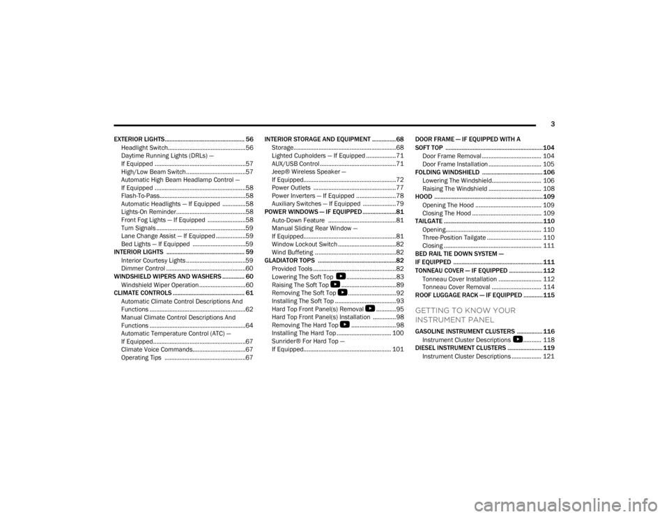
EXTERIOR LIGHTS.................................................. 56 Headlight Switch...............................................56
Daytime Running Lights (DRLs) —
If Equipped .......................................................57
High/Low Beam Switch....................................57
Automatic High Beam Headlamp Control —
If Equipped .......................................................58
Flash-To-Pass....................................................58
Automatic Headlights — If Equipped ..............58
Lights-On Reminder..........................................58
Front Fog Lights — If Equipped .......................58
Turn Signals ......................................................59
Lane Change Assist — If Equipped ..................59
Bed Lights — If Equipped ................................59
INTERIOR LIGHTS ................................................. 59
Interior Courtesy Lights ....................................59
Dimmer Control ................................................60
WINDSHIELD WIPERS AND WASHERS .............. 60
Windshield Wiper Operation ............................60
CLIMATE CONTROLS ............................................. 61
Automatic Climate Control Descriptions And
Functions ..........................................................62
Manual Climate Control Descriptions And
Functions ..........................................................64
Automatic Temperature Control (ATC) —
If Equipped........................................................67
Climate Voice Commands................................67
Operating Tips .................................................67 INTERIOR STORAGE AND EQUIPMENT ............... 68
Storage..............................................................68
Lighted Cupholders — If Equipped ..................71
AUX/USB Control ..............................................71
Jeep® Wireless Speaker —
If Equipped........................................................72
Power Outlets ..................................................77
Power Inverters — If Equipped ........................78
Auxiliary Switches — If Equipped ....................79
POWER WINDOWS — IF EQUIPPED .....................81
Auto-Down Feature .........................................81
Manual Sliding Rear Window —
If Equipped........................................................81
Window Lockout Switch ...................................82
Wind Buffeting .................................................82
GLADIATOR TOPS .................................................82
Provided Tools ..................................................82
Lowering The Soft Top
S
..............................83
Raising The Soft Top
S
.................................89
Removing The Soft Top
S
.............................92
Installing The Soft Top .....................................93
Hard Top Front Panel(s) Removal
S
............95
Hard Top Front Panel(s) Installation ..............98
Removing The Hard Top
S
...........................98
Installing The Hard Top ................................. 100
Sunrider® For Hard Top —
If Equipped..................................................... 101 DOOR FRAME — IF EQUIPPED WITH A
SOFT TOP ............................................................. 104
Door Frame Removal .................................... 104
Door Frame Installation ................................ 105
FOLDING WINDSHIELD ...................................... 106
Lowering The Windshield.............................. 106
Raising The Windshield ................................ 108
HOOD .................................................................... 109
Opening The Hood ........................................ 109
Closing The Hood .......................................... 109
TAILGATE .............................................................. 110
Opening.......................................................... 110Three-Position Tailgate ................................. 110
Closing ........................................................... 111
BED RAIL TIE DOWN SYSTEM —
IF EQUIPPED ........................................................ 111
TONNEAU COVER — IF EQUIPPED ..................... 112
Tonneau Cover Installation .......................... 112
Tonneau Cover Removal .............................. 114
ROOF LUGGAGE RACK — IF EQUIPPED ............ 115
GETTING TO KNOW YOUR
INSTRUMENT PANEL
GASOLINE INSTRUMENT CLUSTERS ................ 116
Instrument Cluster Descriptions
S
........... 118
DIESEL INSTRUMENT CLUSTERS ...................... 119
Instrument Cluster Descriptions .................. 121
23_JT_OM_EN_USC_t.book Page 3
Page 6 of 448
4
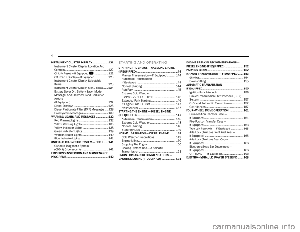
INSTRUMENT CLUSTER DISPLAY ...................... 121 Instrument Cluster Display Location And
Controls .......................................................... 122
Oil Life Reset — If Equipped
S
................... 122
Off Road+ Display — If Equipped .................. 123
Instrument Cluster Display Selectable
Items .............................................................. 123
Instrument Cluster Display Menu Items ...... 124
Battery Saver On, Battery Saver Mode
Message, And Electrical Load Reduction
Actions
(If Equipped) .................................................. 127
Diesel Displays .............................................. 128 Diesel Particulate Filter (DPF) Messages .... 128Fuel System Messages ................................. 130
WARNING LIGHTS AND MESSAGES ................. 132
Red Warning Lights ....................................... 132
Yellow Warning Lights ................................... 135Yellow Indicator Lights .................................. 138
Green Indicator Lights................................... 139White Indicator Lights ................................... 140Blue Indicator Lights ..................................... 141
ONBOARD DIAGNOSTIC SYSTEM — OBD II ...... 141
Onboard Diagnostic System
(OBD II) Cybersecurity ................................... 142
EMISSIONS INSPECTION AND MAINTENANCE
PROGRAMS .......................................................... 142
STARTING AND OPERATING
STARTING THE ENGINE — GASOLINE ENGINE
(IF EQUIPPED) ...................................................... 144
Manual Transmission — If Equipped ........... 144Automatic Transmission —
If Equipped .................................................... 144
Normal Starting ............................................ 144
AutoPark ........................................................ 145Extreme Cold Weather
(Below –22°F Or −30°C) ............................ 146
Extended Park Starting ................................. 146
If Engine Fails To Start ................................. 147
After Starting ................................................. 147
STARTING THE ENGINE — DIESEL ENGINE
(IF EQUIPPED) ...................................................... 147
Automatic Transmission ............................... 148
Extreme Cold Weather .................................. 148
Normal Starting ............................................. 148Starting Fluids ............................................... 149
NORMAL OPERATION — DIESEL ENGINE ......... 149
Cold Weather Precautions ............................ 149
Engine Idling .................................................. 150
Stopping The Engine ..................................... 150
Cooling System Tips — Automatic
Transmission ................................................. 151
ENGINE BREAK-IN RECOMMENDATIONS —
GASOLINE ENGINE (IF EQUIPPED) ................... 151 ENGINE BREAK-IN RECOMMENDATIONS —
DIESEL ENGINE (IF EQUIPPED) .......................... 152
PARKING BRAKE ................................................. 152
MANUAL TRANSMISSION — IF EQUIPPED ....... 153
Shifting........................................................... 154
Downshifting.................................................. 155
AUTOMATIC TRANSMISSION —
IF EQUIPPED ......................................................... 155
Ignition Park Interlock................................... 156
Brake/Transmission Shift Interlock (BTSI)
System .......................................................... 1578–Speed Automatic Transmission .............. 157
Gear Ranges .................................................. 157
FOUR–WHEEL DRIVE OPERATION ................... 161
Four-Position Transfer Case —
If Equipped .................................................... 161
Five-Position Transfer Case —
If Equipped .................................................... 163
Trac-Lok Rear Axle — If Equipped ................ 165Axle Lock (Tru-Lok) Front And Rear —
If Equipped ................................................... 165
Axle Lock (Tru-Lok) Rear Only —
If Equipped ................................................... 166
Electronic Sway Bar Disconnect —
If Equipped ................................................... 166
OFF ROAD+ — If Equipped ............................ 168
ELECTRO-HYDRAULIC POWER STEERING ....... 168
23_JT_OM_EN_USC_t.book Page 4
Page 8 of 448
6
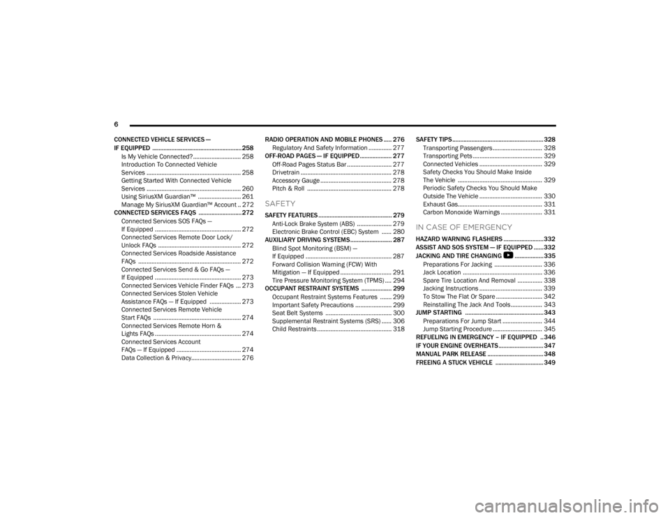
CONNECTED VEHICLE SERVICES —
IF EQUIPPED ........................................................ 258 Is My Vehicle Connected?............................. 258
Introduction To Connected Vehicle
Services ......................................................... 258
Getting Started With Connected Vehicle
Services ......................................................... 260
Using SiriusXM Guardian™ .......................... 261
Manage My SiriusXM Guardian™ Account .. 272
CONNECTED SERVICES FAQS ........................... 272
Connected Services SOS FAQs —
If Equipped .................................................... 272
Connected Services Remote Door Lock/
Unlock FAQs .................................................. 272
Connected Services Roadside Assistance
FAQs .............................................................. 272
Connected Services Send & Go FAQs —
If Equipped .................................................... 273
Connected Services Vehicle Finder FAQs ... 273
Connected Services Stolen Vehicle
Assistance FAQs — If Equipped ................... 273
Connected Services Remote Vehicle
Start FAQs ..................................................... 274
Connected Services Remote Horn &
Lights FAQs .................................................... 274
Connected Services Account
FAQs — If Equipped ....................................... 274
Data Collection & Privacy.............................. 276 RADIO OPERATION AND MOBILE PHONES ..... 276
Regulatory And Safety Information .............. 277
OFF-ROAD PAGES — IF EQUIPPED.................... 277
Off-Road Pages Status Bar ........................... 277Drivetrain ....................................................... 278
Accessory Gauge ........................................... 278Pitch & Roll ................................................... 278
SAFETY
SAFETY FEATURES .............................................. 279
Anti-Lock Brake System (ABS) ..................... 279
Electronic Brake Control (EBC) System ...... 280
AUXILIARY DRIVING SYSTEMS.......................... 287
Blind Spot Monitoring (BSM) —
If Equipped .................................................... 287
Forward Collision Warning (FCW) With
Mitigation — If Equipped ............................... 291
Tire Pressure Monitoring System (TPMS) .... 294
OCCUPANT RESTRAINT SYSTEMS ................... 299
Occupant Restraint Systems Features ....... 299
Important Safety Precautions ...................... 299Seat Belt Systems ........................................ 300Supplemental Restraint Systems (SRS) ...... 306Child Restraints ............................................. 318 SAFETY TIPS ......................................................... 328
Transporting Passengers.............................. 328
Transporting Pets .......................................... 329Connected Vehicles ...................................... 329
Safety Checks You Should Make Inside
The Vehicle ................................................... 329
Periodic Safety Checks You Should Make
Outside The Vehicle ...................................... 330
Exhaust Gas................................................... 331
Carbon Monoxide Warnings ......................... 331
IN CASE OF EMERGENCY
HAZARD WARNING FLASHERS ......................... 332
ASSIST AND SOS SYSTEM — IF EQUIPPED ...... 332
JACKING AND TIRE CHANGING
S
.................. 335
Preparations For Jacking ............................. 336 Jack Location ................................................ 336
Spare Tire Location And Removal ............... 338
Jacking Instructions ...................................... 339
To Stow The Flat Or Spare ............................ 342
Reinstalling The Jack And Tools ................... 343
JUMP STARTING ................................................. 343
Preparations For Jump Start ........................ 344Jump Starting Procedure .............................. 345
REFUELING IN EMERGENCY – IF EQUIPPED .. 346
IF YOUR ENGINE OVERHEATS ............................ 347
MANUAL PARK RELEASE ................................... 348
FREEING A STUCK VEHICLE .............................. 349
23_JT_OM_EN_USC_t.book Page 6
Page 13 of 448
11
CAMPERS
This vehicle is NOT recommended for slide-in camper applications.
VEHICLE MODIFICATIONS/ALTERATIONS
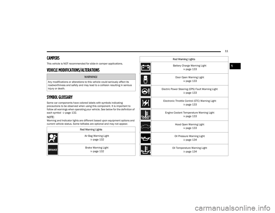
SYMBOL GLOSSARY
Some car components have colored labels with symbols indicating
precautions to be observed when using this component. It is important to
follow all warnings when operating your vehicle. See below for the definition of
each symbol Úpage 132.
NOTE:Warning and Indicator lights are different based upon equipment options and
current vehicle status. Some telltales are optional and may not appear.
WARNING!
Any modifications or alterations to this vehicle could seriously affect its
roadworthiness and safety and may lead to a collision resulting in serious
injury or death.
Red Warning LightsAir Bag Warning Light Úpage 132
Brake Warning Light Úpage 132
Battery Charge Warning Light
Úpage 133
Door Open Warning Light Úpage 133
Electric Power Steering (EPS) Fault Warning Light Úpage 133
Electronic Throttle Control (ETC) Warning Light Úpage 133
Engine Coolant Temperature Warning Light Úpage 133
Hood Open Warning Light Úpage 133
Oil Pressure Warning Light Úpage 134
Oil Temperature Warning Light Úpage 134
Red Warning Lights1
23_JT_OM_EN_USC_t.book Page 11
Page 14 of 448
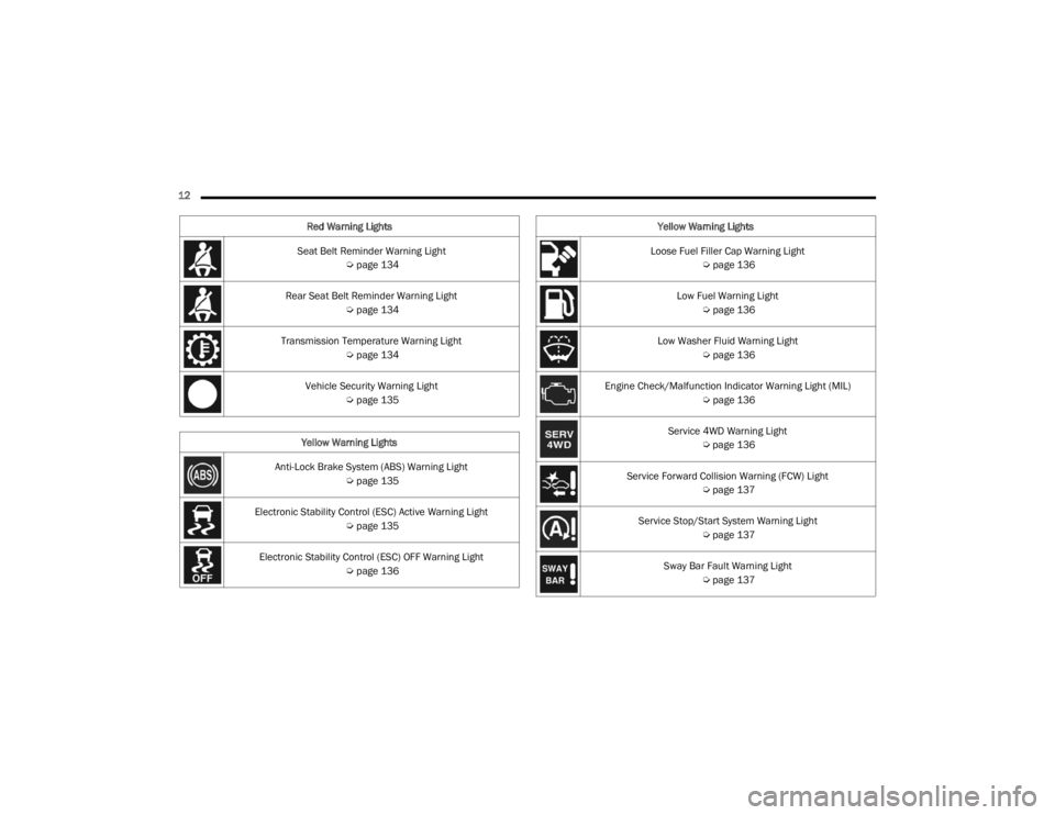
12 Seat Belt Reminder Warning Light Úpage 134
Rear Seat Belt Reminder Warning Light Úpage 134
Transmission Temperature Warning Light Úpage 134
Vehicle Security Warning Light Úpage 135
Yellow Warning Lights
Anti-Lock Brake System (ABS) Warning Light Úpage 135
Electronic Stability Control (ESC) Active Warning Light Úpage 135
Electronic Stability Control (ESC) OFF Warning Light Úpage 136
Red Warning Lights
Loose Fuel Filler Cap Warning Light
Úpage 136
Low Fuel Warning Light Úpage 136
Low Washer Fluid Warning Light Úpage 136
Engine Check/Malfunction Indicator Warning Light (MIL) Úpage 136
Service 4WD Warning Light Úpage 136
Service Forward Collision Warning (FCW) Light Úpage 137
Service Stop/Start System Warning Light Úpage 137
Sway Bar Fault Warning Light Úpage 137
Yellow Warning Lights
23_JT_OM_EN_USC_t.book Page 12
Page 15 of 448
13
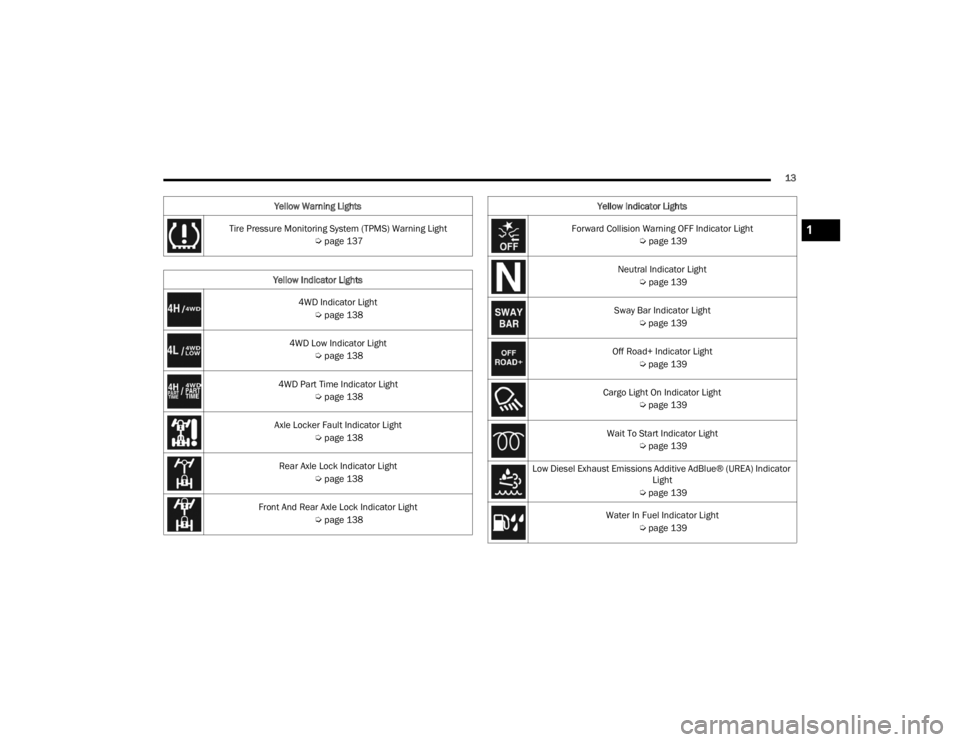
Tire Pressure Monitoring System (TPMS) Warning Light Úpage 137
Yellow Indicator Lights 4WD Indicator Light Úpage 138
4WD Low Indicator Light Úpage 138
4WD Part Time Indicator Light Úpage 138
Axle Locker Fault Indicator Light Úpage 138
Rear Axle Lock Indicator Light Úpage 138
Front And Rear Axle Lock Indicator Light Úpage 138
Yellow Warning Lights
Forward Collision Warning OFF Indicator Light
Úpage 139
Neutral Indicator Light Úpage 139
Sway Bar Indicator Light Úpage 139
Off Road+ Indicator Light Úpage 139
Cargo Light On Indicator Light Úpage 139
Wait To Start Indicator Light Úpage 139
Low Diesel Exhaust Emissions Additive AdBlue® (UREA) Indicator Light
Ú page 139
Water In Fuel Indicator Light Úpage 139
Yellow Indicator Lights1
23_JT_OM_EN_USC_t.book Page 13
Page 16 of 448
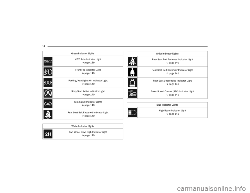
14 Green Indicator Lights4WD Auto Indicator Light Úpage 139
Front Fog Indicator Light Úpage 140
Parking/Headlights On Indicator Light Úpage 140
Stop/Start Active Indicator Light Úpage 140
Turn Signal Indicator Lights Úpage 140
Rear Seat Belt Fastened Indicator Light Úpage 140
White Indicator Lights
Two Wheel Drive High Indicator Light Úpage 140
Rear Seat Belt Fastened Indicator Light
Úpage 140
Rear Seat Belt Reminder Indicator Light Úpage 141
Rear Seat Unoccupied Indicator Light Úpage 141
Selec-Speed Control (SSC) Indicator Light Úpage 141
Blue Indicator Lights High Beam Indicator Light Úpage 141
White Indicator Lights
23_JT_OM_EN_USC_t.book Page 14
Page 17 of 448
15
GETTING TO KNOW YOUR VEHICLE
KEYS
KEY FOB
Your vehicle is equipped with a key fob which
supports Passive Entry, Remote Keyless Entry
(RKE), Keyless Enter ‘n Go™ (if equipped), and
Remote Start (if equipped). The key fob allows you to
lock or unlock the doors and tailgate from distances
up to approximately 66 ft (20 m). The key fob does
not need to be pointed at the vehicle to activate the
system. The key fob also contains a mechanical key.
NOTE:
The key fob’s wireless signal may be blocked if
the key fob is located next to a mobile phone,
laptop, or other electronic device. This may
result in poor performance.
With the ignition in the ON/RUN position, and
the vehicle moving at 2 mph (4 km/h), all RKE commands are disabled.
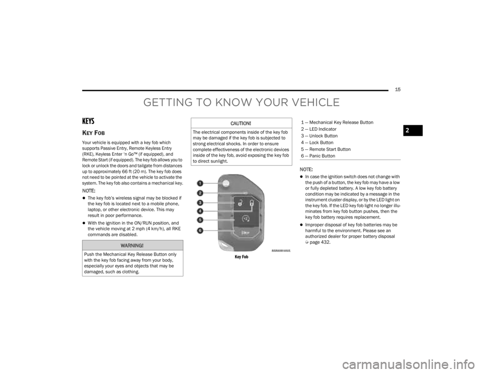
Key Fob
NOTE:
In case the ignition switch does not change with
the push of a button, the key fob may have a low
or fully depleted battery. A low key fob battery
condition may be indicated by a message in the
instrument cluster display, or by the LED light on
the key fob. If the LED key fob light no longer illu-
minates from key fob button pushes, then the
key fob battery requires replacement.
Improper disposal of key fob batteries may be
harmful to the environment. Please see an
authorized dealer for proper battery disposal
Ú page 432.
WARNING!
Push the Mechanical Key Release Button only
with the key fob facing away from your body,
especially your eyes and objects that may be
damaged, such as clothing.
CAUTION!
The electrical components inside of the key fob
may be damaged if the key fob is subjected to
strong electrical shocks. In order to ensure
complete effectiveness of the electronic devices
inside of the key fob, avoid exposing the key fob
to direct sunlight.
1 — Mechanical Key Release Button
2 — LED Indicator
3 — Unlock Button
4 — Lock Button
5 — Remote Start Button
6 — Panic Button
2
23_JT_OM_EN_USC_t.book Page 15
Page 18 of 448
16GETTING TO KNOW YOUR VEHICLE
To Lock/Unlock The Doors And Tailgate
Push and release the unlock button on the key fob
once to unlock the driver’s door, or twice to unlock
all the doors. To lock all the doors, push the lock
button once.
When the doors are unlocked, the turn signals will
flash and the illuminated entry system will be
activated. When the doors are locked, the turn
signals will flash and the horn will chirp.
NOTE:
All doors can be programmed to unlock on the
first push of the unlock button through
Uconnect Settings Úpage 215.
The mechanical flip key can be used to lock or
unlock the doors, tailgate, glove compartment,
storage compartments (if equipped), and rear
seatbacks.
Key Left Vehicle Feature
If a valid key fob is no longer detected inside the
vehicle while the vehicle’s ignition system is in the
ON/RUN or START position, the message “Key Fob
Has Left The Vehicle” will be shown in the
instrument cluster display along with an interior
chime. An exterior audible and visual alert will also
be activated to warn the driver. The vehicle’s horn will rapidly chirp three times
along with a single flash of the vehicle’s exterior
lights.
NOTE:
The doors have to be open and then closed in
order for the vehicle to check for the presence of
a key fob; the Key Left Vehicle feature will not
activate until all of the doors are closed.
These alerts will not be activated in situations
where the vehicle’s engine is left running with
the key fob inside.
Replacing The Battery In The Key Fob
The recommended replacement battery is
CR2450.
NOTE:
Customers are recommended to use a battery
obtained from Mopar®. Aftermarket coin
battery dimensions may not meet the original
OEM coin battery dimensions.
Perchlorate material — special handling may
apply. See www.dtsc.ca.gov/hazardouswaste/
perchlorate for further information.
Do not touch the battery terminals that are on
the back housing or the printed circuit board.
When a key fob battery is low, a warning will be
indicated on the vehicle’s instrument cluster,
and the fob LED will no longer illuminate with a
button push.
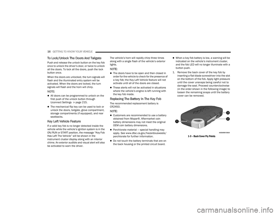
1. Remove the back cover of the key fob by inserting a flat-blade screwdriver into the slot
on the bottom of the fob. Apply light pressure
until the cover unsnaps being careful not to
damage the seal. Proceed counterclockwise
(in the order shown in the following image) to
loosen the remaining snaps until the battery
cover can be removed.
1-3 – Back Cover Pry Points
23_JT_OM_EN_USC_t.book Page 16
Page 20 of 448
18GETTING TO KNOW YOUR VEHICLE
The system uses a key fob, keyless push button
ignition and a Radio Frequency (RF) receiver to
prevent unauthorized vehicle operation. Therefore,
only key fobs that are programmed to the vehicle
can be used to start and operate the vehicle. The
system cannot reprogram a key fob obtained from
another vehicle.
After placing the ignition switch in the ON/RUN
position, the Vehicle Security Light will turn on for
three seconds for a bulb check. If the light remains
on after the bulb check, it indicates that there is a
problem with the electronics. In addition, if the light
begins to flash after the bulb check, it indicates
that someone attempted to start the engine with
an invalid key fob. In the event that a valid key fob
is used to start the engine but there is an issue
with the vehicle electronics, the engine will start
and shut off after two seconds.
If the Vehicle Security Light turns on during normal
vehicle operation (vehicle running for longer than
ten seconds), it indicates that there is a fault in the
electronics. Should this occur, have the vehicle
serviced as soon as possible by an authorized
dealer. All of the key fobs provided with your new vehicle
have been programmed to the vehicle electronics
Ú
page 432.
NOTE:A key fob that has not been programmed is also
considered an invalid key.
IGNITION SWITCH
KEYLESS ENTER ‘N GO™ IGNITION
This feature allows the driver to operate the
ignition switch with the push of a START/STOP
ignition button as long as the key fob is in the
passenger compartment.
The START/STOP ignition button has several
operating modes that are labeled and will
illuminate when in position. These modes are OFF,
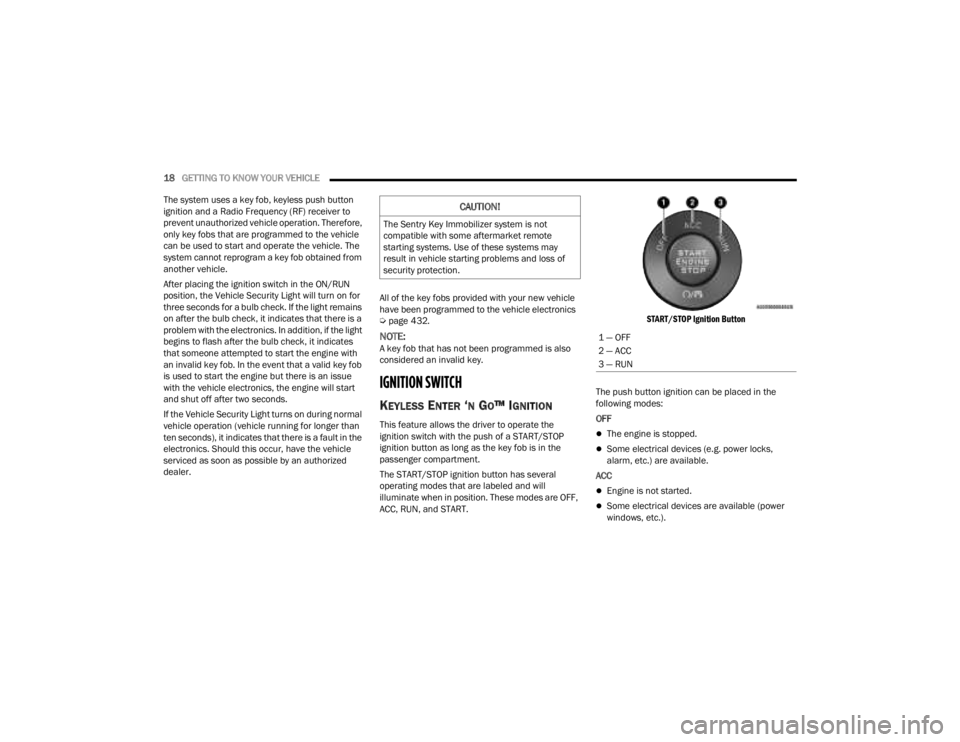
ACC, RUN, and START.
START/STOP Ignition Button
The push button ignition can be placed in the
following modes:
OFF The engine is stopped.
Some electrical devices (e.g. power locks,
alarm, etc.) are available.
ACC
Engine is not started.
Some electrical devices are available (power
windows, etc.).
CAUTION!
The Sentry Key Immobilizer system is not
compatible with some aftermarket remote
starting systems. Use of these systems may
result in vehicle starting problems and loss of
security protection.
1 — OFF
2 — ACC
3 — RUN
23_JT_OM_EN_USC_t.book Page 18