tow bar JEEP GLADIATOR 2023 Owners Manual
[x] Cancel search | Manufacturer: JEEP, Model Year: 2023, Model line: GLADIATOR, Model: JEEP GLADIATOR 2023Pages: 448, PDF Size: 17.37 MB
Page 7 of 448
5
STOP/START SYSTEM — AUTOMATIC
TRANSMISSION (IF EQUIPPED) ........................ 169 Autostop Mode .............................................. 169Possible Reasons The Engine Does Not
Autostop ......................................................... 170
To Start The Engine While In Autostop
Mode .............................................................. 170
To Manually Turn Off The Stop/Start
System ........................................................... 171To Manually Turn On The Stop/Start
System ........................................................... 171System Malfunction ...................................... 171
STOP/START SYSTEM — MANUAL
TRANSMISSION (IF EQUIPPED) .........................171
Autostop Mode .............................................. 172Possible Reasons The Engine Does Not
Autostop ......................................................... 172
To Start The Engine While In Autostop
Mode .............................................................. 172
To Manually Turn Off The Stop/Start
System ........................................................... 173To Manually Turn On The Stop/Start
System ........................................................... 173System Malfunction ...................................... 173
CRUISE CONTROL SYSTEMS —
IF EQUIPPED ........................................................ 173
Cruise Control ............................................... 173
Adaptive Cruise Control (ACC) ...................... 175 PARKSENSE FRONT/REAR PARK ASSIST
SYSTEM — IF EQUIPPED .................................... 184
ParkSense Sensors ....................................... 184
ParkSense Warning Display ......................... 184
ParkSense Display ........................................ 184Enabling And Disabling ParkSense .............. 187Service The ParkSense Park Assist
System ........................................................... 187
Cleaning The ParkSense System ................. 187
ParkSense System Usage Precautions........ 188
PARKVIEW REAR BACK UP CAMERA............... 189
TRAILCAM SYSTEM — IF EQUIPPED ................ 190
REFUELING THE VEHICLE — GASOLINE
ENGINE (IF EQUIPPED) ....................................... 191 Fuel Filler Cap................................................ 191Loose Fuel Filler Cap Message ................... 192
REFUELING THE VEHICLE — DIESEL ENGINE
(IF EQUIPPED) ..................................................... 192
Avoid Using Contaminated Fuel ................... 193Bulk Fuel Storage — Diesel Fuel................... 193Diesel Exhaust Fluid ..................................... 193
VEHICLE LOADING .............................................. 195
Certification Label ......................................... 195
TRAILER TOWING ............................................... 197
Common Towing Definitions......................... 197
Trailer Hitch Classification ............................ 199
Trailer Towing Weights (Maximum Trailer
Weight Ratings) ............................................ 199
Trailer And Tongue Weight............................ 202
Towing Requirements ................................... 202Towing Tips .................................................... 204 RECREATIONAL TOWING (BEHIND
MOTORHOME) ...................................................... 205
Towing This Vehicle Behind Another
Vehicle ........................................................... 205
Recreational Towing — Four-Wheel Drive
Models ........................................................... 205
DRIVING TIPS ....................................................... 207
On-Road Driving Tips..................................... 207Off-Road Driving Tips .................................... 207
MULTIMEDIA
UCONNECT SYSTEMS ......................................... 214
CYBERSECURITY ................................................. 214
UCONNECT SETTINGS ......................................... 215 Customer Programmable Features ............. 215
UCONNECT INTRODUCTION................................ 230
System Overview .......................................... 230Drag & Drop Menu Bar ................................. 232
Safety And General Information................... 232
UCONNECT MODES ............................................. 233
Steering Wheel Audio Controls .................... 233
Radio Mode .................................................. 234Media Mode ................................................. 242
Phone Mode ................................................. 244
ANDROID AUTO™ & APPLE CARPLAY® —
IF EQUIPPED ......................................................... 254
Android Auto™
S
........................................ 254
Apple CarPlay®
S
....................................... 256
Android Auto™ And Apple CarPlay® Tips
And Tricks ...................................................... 258
23_JT_OM_EN_USC_t.book Page 5
Page 8 of 448
6
CONNECTED VEHICLE SERVICES —
IF EQUIPPED ........................................................ 258 Is My Vehicle Connected?............................. 258
Introduction To Connected Vehicle
Services ......................................................... 258
Getting Started With Connected Vehicle
Services ......................................................... 260
Using SiriusXM Guardian™ .......................... 261
Manage My SiriusXM Guardian™ Account .. 272
CONNECTED SERVICES FAQS ........................... 272
Connected Services SOS FAQs —
If Equipped .................................................... 272
Connected Services Remote Door Lock/
Unlock FAQs .................................................. 272
Connected Services Roadside Assistance
FAQs .............................................................. 272
Connected Services Send & Go FAQs —
If Equipped .................................................... 273
Connected Services Vehicle Finder FAQs ... 273
Connected Services Stolen Vehicle
Assistance FAQs — If Equipped ................... 273
Connected Services Remote Vehicle
Start FAQs ..................................................... 274
Connected Services Remote Horn &
Lights FAQs .................................................... 274
Connected Services Account
FAQs — If Equipped ....................................... 274
Data Collection & Privacy.............................. 276 RADIO OPERATION AND MOBILE PHONES ..... 276
Regulatory And Safety Information .............. 277
OFF-ROAD PAGES — IF EQUIPPED.................... 277
Off-Road Pages Status Bar ........................... 277Drivetrain ....................................................... 278
Accessory Gauge ........................................... 278Pitch & Roll ................................................... 278
SAFETY
SAFETY FEATURES .............................................. 279
Anti-Lock Brake System (ABS) ..................... 279
Electronic Brake Control (EBC) System ...... 280
AUXILIARY DRIVING SYSTEMS.......................... 287
Blind Spot Monitoring (BSM) —
If Equipped .................................................... 287
Forward Collision Warning (FCW) With
Mitigation — If Equipped ............................... 291
Tire Pressure Monitoring System (TPMS) .... 294
OCCUPANT RESTRAINT SYSTEMS ................... 299
Occupant Restraint Systems Features ....... 299
Important Safety Precautions ...................... 299Seat Belt Systems ........................................ 300Supplemental Restraint Systems (SRS) ...... 306Child Restraints ............................................. 318 SAFETY TIPS ......................................................... 328
Transporting Passengers.............................. 328
Transporting Pets .......................................... 329Connected Vehicles ...................................... 329
Safety Checks You Should Make Inside
The Vehicle ................................................... 329
Periodic Safety Checks You Should Make
Outside The Vehicle ...................................... 330
Exhaust Gas................................................... 331
Carbon Monoxide Warnings ......................... 331
IN CASE OF EMERGENCY
HAZARD WARNING FLASHERS ......................... 332
ASSIST AND SOS SYSTEM — IF EQUIPPED ...... 332
JACKING AND TIRE CHANGING
S
.................. 335
Preparations For Jacking ............................. 336 Jack Location ................................................ 336
Spare Tire Location And Removal ............... 338
Jacking Instructions ...................................... 339
To Stow The Flat Or Spare ............................ 342
Reinstalling The Jack And Tools ................... 343
JUMP STARTING ................................................. 343
Preparations For Jump Start ........................ 344Jump Starting Procedure .............................. 345
REFUELING IN EMERGENCY – IF EQUIPPED .. 346
IF YOUR ENGINE OVERHEATS ............................ 347
MANUAL PARK RELEASE ................................... 348
FREEING A STUCK VEHICLE .............................. 349
23_JT_OM_EN_USC_t.book Page 6
Page 52 of 448
50GETTING TO KNOW YOUR VEHICLE
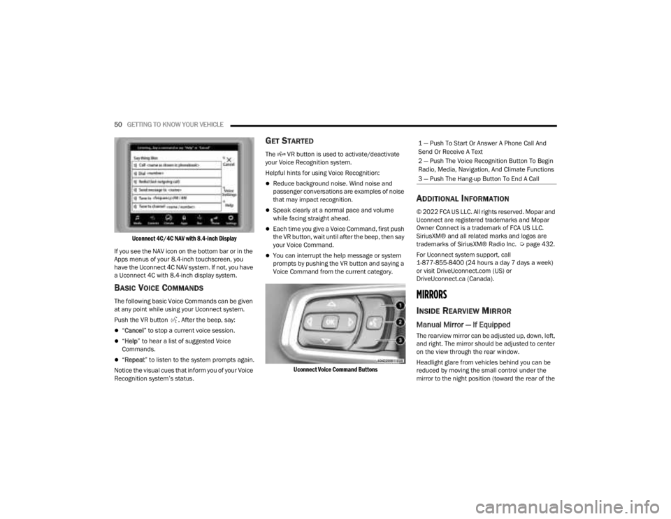
Uconnect 4C/4C NAV with 8.4-inch Display
If you see the NAV icon on the bottom bar or in the
Apps menus of your 8.4-inch touchscreen, you
have the Uconnect 4C NAV system. If not, you have
a Uconnect 4C with 8.4-inch display system.
BASIC VOICE COMMANDS
The following basic Voice Commands can be given
at any point while using your Uconnect system.
Push the VR button . After the beep, say:
“ Cancel ” to stop a current voice session.
“Help ” to hear a list of suggested Voice
Commands.
“ Repeat ” to listen to the system prompts again.
Notice the visual cues that inform you of your Voice
Recognition system’s status.
GET STARTED
The VR button is used to activate/deactivate
your Voice Recognition system.
Helpful hints for using Voice Recognition:
Reduce background noise. Wind noise and
passenger conversations are examples of noise
that may impact recognition.
Speak clearly at a normal pace and volume
while facing straight ahead.
Each time you give a Voice Command, first push
the VR button, wait until after the beep, then say
your Voice Command.
You can interrupt the help message or system
prompts by pushing the VR button and saying a
Voice Command from the current category.
Uconnect Voice Command Buttons
ADDITIONAL INFORMATION
© 2022 FCA US LLC. All rights reserved. Mopar and
Uconnect are registered trademarks and Mopar
Owner Connect is a trademark of FCA US LLC.
SiriusXM® and all related marks and logos are
trademarks of SiriusXM® Radio Inc. Ú page 432.
For Uconnect system support, call
1-877-855-8400 (24 hours a day 7 days a week)
or visit DriveUconnect.com (US) or
DriveUconnect.ca (Canada).
MIRRORS
INSIDE REARVIEW MIRROR
Manual Mirror — If Equipped
The rearview mirror can be adjusted up, down, left,
and right. The mirror should be adjusted to center
on the view through the rear window.
Headlight glare from vehicles behind you can be
reduced by moving the small control under the
mirror to the night position (toward the rear of the
1 — Push To Start Or Answer A Phone Call And
Send Or Receive A Text
2 — Push The Voice Recognition Button To Begin
Radio, Media, Navigation, And Climate Functions
3 — Push The Hang-up Button To End A Call
23_JT_OM_EN_USC_t.book Page 50
Page 65 of 448
GETTING TO KNOW YOUR VEHICLE63
AUTO Button
Press and release this button on the
touchscreen, or push the button on the
faceplate, to change the current setting.
The AUTO indicator illuminates when
AUTO is on. This feature automatically controls the
interior cabin temperature by adjusting distribution
and blower speed. Air conditioning (A/C) may be
active during AUTO operation to improve
performance. AUTO Mode is highly recommended
for efficiency. Toggling this function will cause the
system to switch between manual mode and
automatic mode Ú page 67.
Front Defrost
Turn the Mode control knob to Front
Defrost to change the current airflow
setting to Defrost mode. The Front
Defrost indicator illuminates when Front
Defrost is on. Air comes from the windshield and
side window demist outlets. When the defrost
button is selected, the blower level may increase.
Use Defrost mode with maximum temperature
settings for best windshield and side window
defrosting and defogging. When toggling the front
defrost mode button, the Climate Control system
will return to the previous setting.
Rear Defrost Button
Press and release the Rear Defrost
Control button on the touchscreen, or
push and release the button on the
faceplate to turn on the rear window
defroster and the heated outside mirrors (if
equipped). The Rear Defrost indicator illuminates
when the rear window defroster is on. The rear
window defroster automatically turns off after
10 minutes.
Driver And Passenger Temperature Up And
Down Buttons
These buttons provide the driver and passenger
with independent temperature control.
Push the red button on the faceplate or
touchscreen or press and slide the
temperature bar towards the red arrow
button on the touchscreen for warmer
temperature settings.
Push the blue button on the faceplate or
touchscreen or press and slide the
temperature bar towards the blue arrow
button on the touchscreen for cooler
temperature settings.
SYNC Button
Press the SYNC button on the
touchscreen to toggle the Sync feature
on/off. The SYNC indicator illuminates
when SYNC is on. SYNC is used to
synchronize the passenger temperature setting
with the driver temperature setting. Changing the
passenger temperature setting while in SYNC will
automatically exit this feature.
NOTE:The SYNC button is only available on the touch-
screen.
CAUTION!
Failure to follow these cautions can cause
damage to the heating elements:
Use care when washing the inside of the rear
window. Do not use abrasive window cleaners
on the interior surface of the window. Use a
soft cloth and a mild washing solution, wiping
parallel to the heating elements. Labels can
be peeled off after soaking with warm water.
Do not use scrapers, sharp instruments, or
abrasive window cleaners on the interior
surface of the window.
Keep all objects a safe distance from the
window.
2
23_JT_OM_EN_USC_t.book Page 63
Page 114 of 448

112GETTING TO KNOW YOUR VEHICLE
There are two adjustable utility rail cleats on each
side of the bed that can be used to assist in
securing cargo.
Adjustable Cleat Assembly
Each utility rail cleat must be tightened down in
one of the detents along either utility rail in order to
keep cargo properly secured.
To move the utility rail cleat to any position on the
utility rail, turn the cleat retainer nut counter-
clockwise several times. Then, pull out on the
utility rail cleat and slide it to the detent nearest
the desired location. Make sure the utility rail cleat
is seated in the detent, and tighten the nut. To remove the utility rail cleats from the side utility
rails, slide the cleat to the rectangular cutout
located at the end of the rail toward the front of the
vehicle.
To remove the utility rail cleat from the front utility
rail, slide the cleat to the rectangular cutout
located on the left side of the rail.
TONNEAU COVER — IF EQUIPPED
The Tonneau Cover can be installed on the truck
bed to keep cargo out of view, and protect from
inclement weather.
The Tonneau Cover consists of the following
features:
Easy roll up cover
Tonneau fore/aft locator
Crossbar inside bed locator
Rear latches
Stowage straps
NOTE:The Tonneau Cover can be rolled up and secured
at the front of the truck bed without removing it
completely.
TONNEAU COVER INSTALLATION
To install the Tonneau Cover, proceed as follows:
1. Position the rolled up Tonneau Cover on the
truck bed and align it to the two fastener
locations at the front of the bed.
Fastener Locations
2. Using a #T50 Torx head driver, secure the fasteners to the bed.
3. Lower the tailgate to the fully open position before unrolling the Tonneau Cover.
1 — Utility Rail Detent
2 — Cleat Retainer Nut
3 — Utility Rail Cleat
23_JT_OM_EN_USC_t.book Page 112
Page 115 of 448
GETTING TO KNOW YOUR VEHICLE113
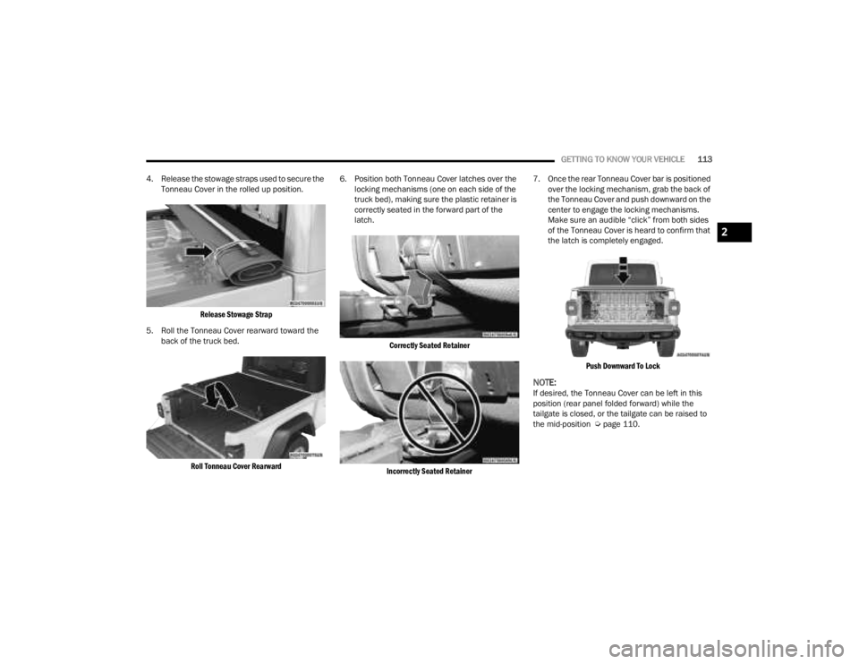
4. Release the stowage straps used to secure the Tonneau Cover in the rolled up position.
Release Stowage Strap
5. Roll the Tonneau Cover rearward toward the back of the truck bed.
Roll Tonneau Cover Rearward
6. Position both Tonneau Cover latches over the
locking mechanisms (one on each side of the
truck bed), making sure the plastic retainer is
correctly seated in the forward part of the
latch.
Correctly Seated Retainer
Incorrectly Seated Retainer
7. Once the rear Tonneau Cover bar is positioned
over the locking mechanism, grab the back of
the Tonneau Cover and push downward on the
center to engage the locking mechanisms.
Make sure an audible “click” from both sides
of the Tonneau Cover is heard to confirm that
the latch is completely engaged.
Push Downward To Lock
NOTE:If desired, the Tonneau Cover can be left in this
position (rear panel folded forward) while the
tailgate is closed, or the tailgate can be raised to
the mid-position Ú page 110.
2
23_JT_OM_EN_USC_t.book Page 113
Page 116 of 448
114GETTING TO KNOW YOUR VEHICLE
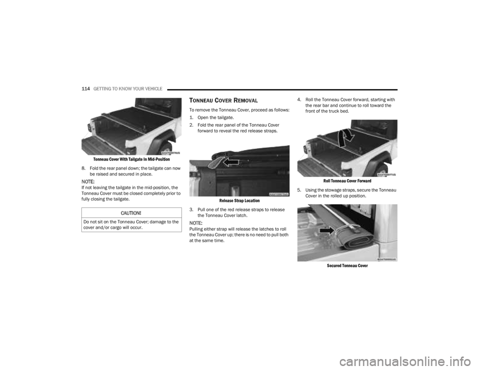
Tonneau Cover With Tailgate In Mid-Position
8. Fold the rear panel down; the tailgate can now be raised and secured in place.
NOTE:If not leaving the tailgate in the mid-position, the
Tonneau Cover must be closed completely prior to
fully closing the tailgate.
TONNEAU COVER REMOVAL
To remove the Tonneau Cover, proceed as follows:
1. Open the tailgate.
2. Fold the rear panel of the Tonneau Cover forward to reveal the red release straps.
Release Strap Location
3. Pull one of the red release straps to release the Tonneau Cover latch.
NOTE:Pulling either strap will release the latches to roll
the Tonneau Cover up; there is no need to pull both
at the same time. 4. Roll the Tonneau Cover forward, starting with
the rear bar and continue to roll toward the
front of the truck bed.
Roll Tonneau Cover Forward
5. Using the stowage straps, secure the Tonneau Cover in the rolled up position.
Secured Tonneau Cover
CAUTION!
Do not sit on the Tonneau Cover; damage to the
cover and/or cargo will occur.
23_JT_OM_EN_USC_t.book Page 114
Page 198 of 448
196STARTING AND OPERATING
This label contains the month and year of
manufacture, Gross Vehicle Weight Rating
(GVWR), front and rear Gross Axle Weight Rating
(GAWR), and Vehicle Identification Number (VIN). A
Month-Day-Hour (MDH) number is included on this
label and indicates the Month, Day and Hour of
manufacture. The bar code that appears on the
bottom of the label is your VIN.
Gross Vehicle Weight Rating (GVWR)
The GVWR is the total permissible weight of your
vehicle including driver, passengers, vehicle,
options and cargo. The label also specifies
maximum capacities of front and rear Gross Axle
Weight Rating (GAWR). Total load must be limited
so GVWR on front and rear GAWR are not
exceeded.
Payload
The payload of a vehicle is defined as the allowable
load weight a truck can carry, including the weight
of the driver, all passengers, options and cargo.
Gross Axle Weight Rating (GAWR)
The GAWR is the maximum permissible load on the
front and rear axles. The load must be distributed
in the cargo area so that the GAWR of each axle is
not exceeded.
Each axle GAWR is determined by the components
in the system with the lowest load carrying capacity
(axle, springs, tires or wheels). Heavier axles or
suspension components sometimes specified by purchasers for increased durability does not
necessarily increase the vehicle's GVWR.
Tire Size
The tire size on the Vehicle Certification Label
represents the actual tire size on your vehicle.
Replacement tires must be equal to the load
capacity of this tire size.
Rim Size
This is the rim size that is appropriate for the tire
size listed.
Inflation Pressure
This is the cold tire inflation pressure for your
vehicle for all loading conditions up to full GAWR.
Curb Weight
The curb weight of a vehicle is defined as the total
weight of the vehicle with all fluids, including
vehicle fuel, at full capacity conditions, and with no
occupants or cargo loaded into the vehicle. The
front and rear curb weight values are determined
by weighing your vehicle on a commercial scale
before any occupants or cargo are added.
Loading
The actual total weight and the weight of the front
and rear of your vehicle at the ground can best be
determined by weighing it when it is loaded and
ready for operation.
The entire vehicle should first be weighed on a
commercial scale to ensure that the GVWR has not
been exceeded. The weight on the front and rear of
the vehicle should then be determined separately
to be sure that the load is properly distributed over
the front and rear axle. Weighing the vehicle may
show that the GAWR of either the front or rear axles
has been exceeded but the total load is within the
specified GVWR. If so, weight must be shifted from
front to rear or rear to front as appropriate until the
specified weight limitations are met. Store the
heavier items down low and be sure that the
weight is distributed equally. Stow all loose items
securely before driving.
Improper weight distributions can have an adverse
effect on the way your vehicle steers and handles
and the way the brakes operate.
WARNING!
Do not load your vehicle any heavier than the
GVWR or the maximum front and rear GAWR. If
you do, parts on your vehicle can break, or it can
change the way your vehicle handles. This could
cause you to lose control. Overloading can
shorten the life of your vehicle.
23_JT_OM_EN_USC_t.book Page 196
Page 199 of 448
STARTING AND OPERATING197
TRAILER TOWING
In this section you will find safety tips and
information on limits to the type of towing you can
reasonably do with your vehicle. Before towing a
trailer, carefully review this information to tow your
load as efficiently and safely as possible.
To maintain the New Vehicle Limited Warranty
coverage, follow the requirements and
recommendations in this manual concerning
vehicles used for trailer towing.
COMMON TOWING DEFINITIONS
The following trailer towing related definitions will
assist you in understanding the following
information:
Gross Vehicle Weight Rating (GVWR)
The GVWR is the total allowable weight of your
vehicle. This includes driver, passengers, cargo
and tongue weight. The total load must be limited
so that you do not exceed the GVWR Ú page 195.
Gross Trailer Weight (GTW)
The GTW is the weight of the trailer plus the weight
of all cargo, consumables and equipment
(permanent or temporary) loaded in or on the trailer
in its "loaded and ready for operation" condition.
The recommended way to measure GTW is to put
your fully loaded trailer on a vehicle scale. The
entire weight of the trailer must be supported by
the scale.
Gross Combination Weight Rating (GCWR)
The GCWR is the total permissible weight of your
vehicle and trailer when weighed in combination.
Gross Axle Weight Rating (GAWR)
The GAWR is the maximum capacity of the front
and rear axles. Distribute the load over the front
and rear axles evenly. Make sure that you do not
exceed either front or rear GAWR Úpage 195.
Tongue Weight (TW)
The TW is the downward force exerted on the hitch
ball by the trailer. You must consider this as part of
the load on your vehicle.
Frontal Area
The frontal area is the maximum height multiplied
by the maximum width of the front of a trailer.
Trailer Sway Control (TSC) — If Equipped
The TSC is a telescoping link that can be installed
between the hitch receiver and the trailer tongue.
It typically provides adjustable friction associated
with the telescoping motion to dampen any
unwanted trailer swaying motions while traveling.
Weight-Carrying Hitch
A weight-carrying hitch supports the trailer tongue
weight, just as if it were luggage located at a hitch
ball or some other connecting point of the vehicle.
These kinds of hitches are commonly used to tow
small and medium sized trailers.
Weight-Distributing Hitch
A Weight-Distributing Hitch system works by
applying leverage through spring (load) bars. They
are typically used for heavier loads to distribute
trailer tongue weight to the tow vehicle's front axle
and the trailer axle(s). When used in accordance
with the manufacturer's directions, it provides for a
more level ride, offering more consistent steering
and brake control thereby enhancing towing
safety. The addition of a friction/hydraulic sway
control also dampens sway caused by traffic and
crosswinds and contributes positively to tow
vehicle and trailer stability. Trailer sway control and
WARNING!
If the gross trailer weight is 2,000 lb (907 kg) or
more, it is recommended to use a weight-
distributing hitch to ensure stable handling of
your vehicle. If you use a standard weight-
carrying hitch, you could lose control of your
vehicle and cause a collision.
WARNING!
It is important that you do not exceed the
maximum front or rear GAWR. A dangerous
driving condition can result if either rating is
exceeded.
4
23_JT_OM_EN_USC_t.book Page 197
Page 208 of 448
206STARTING AND OPERATING
Shifting Into N (Neutral)
Use the following procedure to prepare your
vehicle for recreational towing.
1. Bring the vehicle to a complete stop on level
ground.
2. Press and hold the brake pedal.
3. Shift the automatic transmission into NEUTRAL or press the clutch pedal on a
manual transmission. 4. Turn the engine off.
5. Shift the transfer case lever into N (Neutral).
6. Start the engine.
7. Shift the transmission into DRIVE or REVERSE.
8. Release the brake pedal (and clutch pedal on
manual transmissions) for five seconds and
ensure that there is no vehicle movement.
9. Repeat steps 7 and 8 with automatic transmission in DRIVE or manual transmission
in first gear.
10. Turn the engine off.
11. Firmly apply the parking brake.
12. Shift the transmission into PARK or place manual transmission in gear (NOT in
NEUTRAL).
13. Attach the vehicle to the tow vehicle using a suitable tow bar.
14. Release the parking brake.Automatic transmissions must be placed in
PARK for recreational towing.
Manual transmissions must be placed in gear
(not in Neutral) for recreational towing.
Before recreational towing, perform the proce -
dure outlined under “Shifting Into N (Neutral)”
to be certain that the transfer case is fully in N
(Neutral). Otherwise, internal damage will
result.
Towing this vehicle in violation of the above
requirements can cause severe transmission
and/or transfer case damage. Damage from
improper towing is not covered under the New
Vehicle Limited Warranty.
Do not use a bumper-mounted clamp-on tow
bar on your vehicle. The bumper face bar will
be damaged.
CAUTION!
WARNING!
You or others could be injured or killed if you
leave the vehicle unattended with the transfer
case in the N (Neutral) position without first fully
engaging the parking brake. The transfer case N
(Neutral) position disengages both the front and
rear driveshafts from the powertrain, and will
allow the vehicle to roll, even if the automatic
transmission is in PARK (or manual transmission
is in gear). The parking brake should always be
applied when the driver is not in the vehicle.
CAUTION!
It is necessary to follow these steps to be certain
that the transfer case is fully in N (Neutral)
before recreational towing to prevent damage to
internal parts.CAUTION!
Damage to the transmission may occur if the
transmission is shifted into PARK with the
transfer case in N (Neutral) and the engine
running. With the transfer case in N (Neutral)
ensure that the engine is OFF before shifting the
transmission into PARK.
23_JT_OM_EN_USC_t.book Page 206