Panel JEEP GLADIATOR 2023 Manual PDF
[x] Cancel search | Manufacturer: JEEP, Model Year: 2023, Model line: GLADIATOR, Model: JEEP GLADIATOR 2023Pages: 448, PDF Size: 17.37 MB
Page 144 of 448
142GETTING TO KNOW YOUR INSTRUMENT PANEL
If any of these systems require service, the OBD II
system will turn on the Malfunction Indicator Light
(MIL). It will also store diagnostic codes and other
information to assist your service technician in
making repairs. Although your vehicle will usually
be drivable and not need towing, see an authorized
dealer for service as soon as possible.
ONBOARD DIAGNOSTIC SYSTEM
(OBD II) C
YBERSECURITY
Your vehicle is required to have an OBD II and a
connection port to allow access to information
related to the performance of your emissions
controls. Authorized service technicians may need
to access this information to assist with the
diagnosis and service of your vehicle and
emissions system Ú page 214.
EMISSIONS INSPECTION AND
MAINTENANCE PROGRAMS
In some localities, it may be a legal requirement to
pass an inspection of your vehicle's emissions
control system. Failure to pass could prevent
vehicle registration. For states and/or provinces that require
an Inspection and Maintenance (I/M),
this check verifies the Malfunction
Indicator Light (MIL) is functioning and is
not on when the engine is running, and that the
OBD II system is ready for testing.
The OBD II system may not be ready if your vehicle
was recently serviced, recently had a depleted
battery or a battery replacement. If the OBD II
system should be determined not ready for the I/M
test, your vehicle may fail the test.
Your vehicle has a simple ignition actuated test,
which you can use prior to going to the test station.
To check if your vehicle's OBD II system is ready,
you must do the following:
1. Cycle the ignition switch to the ON position, but do not crank or start the engine.
NOTE:If you crank or start the engine, you will have to
start this test over.
2. As soon as you cycle the ignition switch to the ON position, you will see the Malfunction
Indicator Light (MIL) symbol come on as part of
a normal bulb check.
CAUTION!
Prolonged driving with the MIL on could cause
further damage to the emission control
system. It could also affect fuel economy and
driveability. The vehicle must be serviced
before any emissions tests can be performed.
If the MIL is flashing while the vehicle is
running, severe catalytic converter damage
and power loss will soon occur. Immediate
service is required.
WARNING!
ONLY an authorized service technician should
connect equipment to the OBD II connection
port in order to read the VIN, diagnose, or
service your vehicle.
If unauthorized equipment is connected to the
OBD II connection port, such as a
driver-behavior tracking device, it may:
Be possible that vehicle systems,
including safety related systems, could be
impaired or a loss of vehicle control could
occur that may result in an accident
involving serious injury or death.
Access, or allow others to access, infor -
mation stored in your vehicle systems,
including personal information.
23_JT_OM_EN_USC_t.book Page 142
Page 145 of 448
GETTING TO KNOW YOUR INSTRUMENT PANEL143
3. Approximately 15 seconds later, one of two things will happen:
The MIL will flash for about 10 seconds and
then return to being fully illuminated until
you turn OFF the ignition or start the engine.
This means that your vehicle's OBD II
system is not ready and you should not
proceed to the I/M station.
The MIL will not flash at all and will remain
fully illuminated until you place the ignition
in the off position or start the engine. This
means that your vehicle's OBD II system is
ready and you can proceed to the I/M
station. If your OBD II system is
not ready, you should see
an authorized dealer or repair facility. If your
vehicle was recently serviced or had a battery
failure or replacement, you may need to do nothing
more than drive your vehicle as you normally would
in order for your OBD II system to update. A
recheck with the previously mentioned test routine
may then indicate that the system is now ready.
Regardless of whether your vehicle's OBD II system
is ready, if the MIL is illuminated during normal
vehicle operation you should have your vehicle
serviced before going to the I/M station. The I/M
station can fail your vehicle because the MIL is on
with the engine running.3
23_JT_OM_EN_USC_t.book Page 143
Page 167 of 448
STARTING AND OPERATING165
completed, place the automatic transmission into
DRIVE or release the clutch pedal on a manual
transmission.
NOTE:Shifting into or out of 4L is possible with the vehicle
completely stopped; however, difficulty may occur
due to the mating teeth not being properly aligned.
Several attempts may be required for clutch teeth
alignment and shift completion to occur. The
preferred method is with the vehicle rolling at 1 to
3 mph (2 to 5 km/h). Avoid attempting to engage
or disengage 4L with the vehicle moving faster
than 1 to 3 mph (2 to 5 km/h).
During cold weather, you may experience
increased effort in shifting until the transfer case
fluid warms up. This is normal.
TRAC-LOK REAR AXLE — IF EQUIPPED
The Trac-Lok rear axle provides a constant driving
force to both rear wheels and reduces wheel spin
caused by the loss of traction at one driving wheel.
If traction differs between the two rear wheels, the
differential automatically proportions the usable
torque by providing more torque to the wheel that
has traction.
Trac-Lok is especially helpful during slippery
driving conditions. With both rear wheels on a
slippery surface, a slight application of the
accelerator will supply maximum traction.
AXLE LOCK (TRU-LOK) FRONT AND
R
EAR — IF EQUIPPED
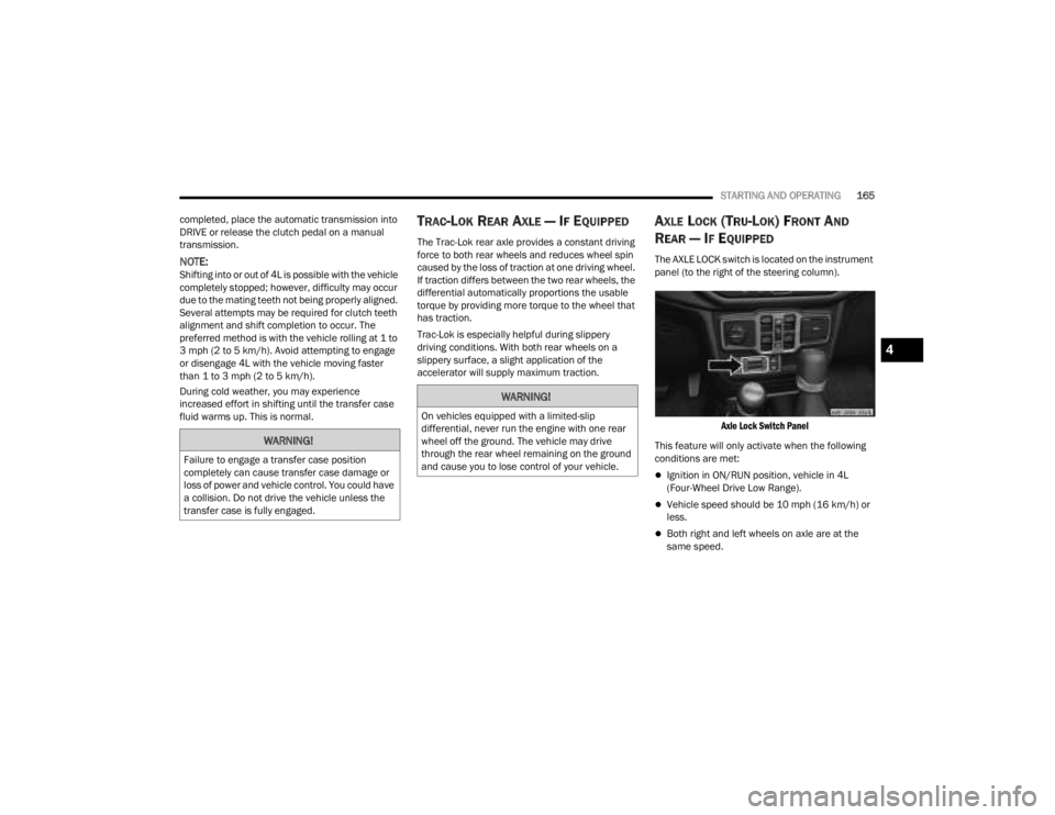
The AXLE LOCK switch is located on the instrument
panel (to the right of the steering column).
Axle Lock Switch Panel
This feature will only activate when the following
conditions are met:
Ignition in ON/RUN position, vehicle in 4L
(Four-Wheel Drive Low Range).
Vehicle speed should be 10 mph (16 km/h) or
less.
Both right and left wheels on axle are at the
same speed.
WARNING!
Failure to engage a transfer case position
completely can cause transfer case damage or
loss of power and vehicle control. You could have
a collision. Do not drive the vehicle unless the
transfer case is fully engaged.
WARNING!
On vehicles equipped with a limited-slip
differential, never run the engine with one rear
wheel off the ground. The vehicle may drive
through the rear wheel remaining on the ground
and cause you to lose control of your vehicle.
4
23_JT_OM_EN_USC_t.book Page 165
Page 168 of 448
166STARTING AND OPERATING
To activate the system, push the AXLE LOCK switch
down to lock the rear axle only (the “REAR ONLY”
will illuminate), push the switch up to lock the front
axle and rear axle (the “FRONT + REAR” will
illuminate). When the rear axle is locked, pushing
the bottom of switch again will lock or unlock the
front axle.
NOTE:The indicator lights will flash until the axles are fully
locked or unlocked.
To unlock the axles, push the AXLE LOCK OFF
button.
Axle Lock will disengage if the vehicle is taken out
of 4L (Four-Wheel Drive Low Range), or the ignition
switch is turned to the OFF position.
The Axle Lock disengages at speeds above 30 mph
(48 km/h), and will automatically re-lock once
vehicle speed is less than 10 mph (16 km/h).
AXLE LOCK (TRU-LOK) REAR ONLY —
I
F EQUIPPED
The rear axle may be locked in 4H if the proper
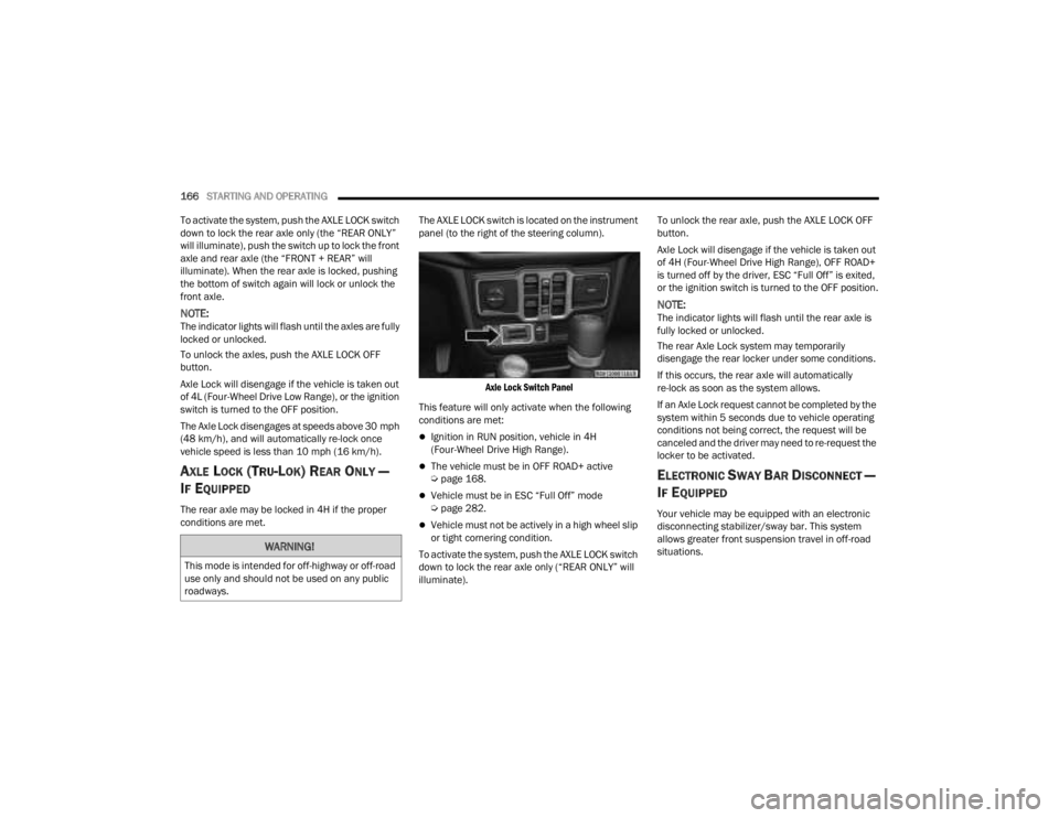
conditions are met. The AXLE LOCK switch is located on the instrument
panel (to the right of the steering column).
Axle Lock Switch Panel
This feature will only activate when the following
conditions are met:
Ignition in RUN position, vehicle in 4H
(Four-Wheel Drive High Range).
The vehicle must be in OFF ROAD+ active
Ú page 168.
Vehicle must be in ESC “Full Off” mode
Úpage 282.
Vehicle must not be actively in a high wheel slip
or tight cornering condition.
To activate the system, push the AXLE LOCK switch
down to lock the rear axle only (“REAR ONLY” will
illuminate). To unlock the rear axle, push the AXLE LOCK OFF
button.
Axle Lock will disengage if the vehicle is taken out
of 4H (Four-Wheel Drive High Range), OFF ROAD+
is turned off by the driver, ESC “Full Off” is exited,
or the ignition switch is turned to the OFF position.
NOTE:The indicator lights will flash until the rear axle is
fully locked or unlocked.
The rear Axle Lock system may temporarily
disengage the rear locker under some conditions.
If this occurs, the rear axle will automatically
re-lock as soon as the system allows.
If an Axle Lock request cannot be completed by the
system within 5 seconds due to vehicle operating
conditions not being correct, the request will be
canceled and the driver may need to re-request the
locker to be activated.
ELECTRONIC SWAY BAR DISCONNECT —
I
F EQUIPPED
Your vehicle may be equipped with an electronic
disconnecting stabilizer/sway bar. This system
allows greater front suspension travel in off-road
situations.
WARNING!
This mode is intended for off-highway or off-road
use only and should not be used on any public
roadways.
23_JT_OM_EN_USC_t.book Page 166
Page 169 of 448
STARTING AND OPERATING167
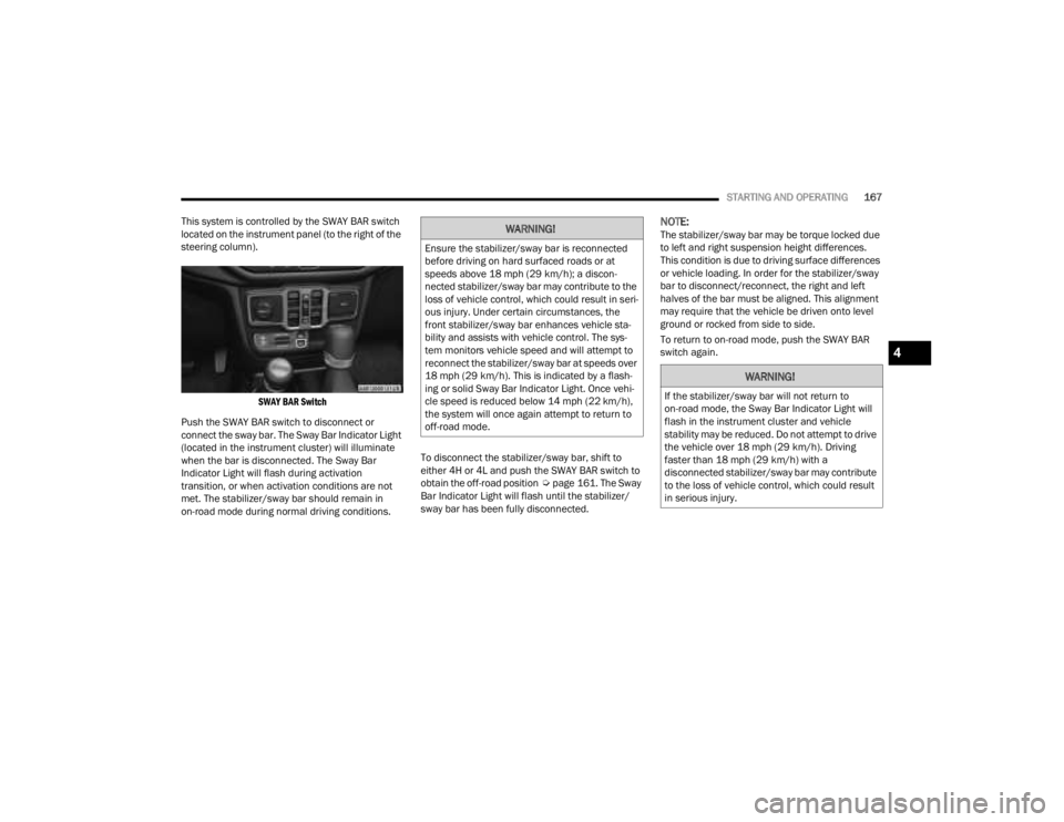
This system is controlled by the SWAY BAR switch
located on the instrument panel (to the right of the
steering column).
SWAY BAR Switch
Push the SWAY BAR switch to disconnect or
connect the sway bar. The Sway Bar Indicator Light
(located in the instrument cluster) will illuminate
when the bar is disconnected. The Sway Bar
Indicator Light will flash during activation
transition, or when activation conditions are not
met. The stabilizer/sway bar should remain in
on-road mode during normal driving conditions. To disconnect the stabilizer/sway bar, shift to
either 4H or 4L and push the SWAY BAR switch to
obtain the off-road position
Úpage 161. The Sway
Bar Indicator Light will flash until the stabilizer/
sway bar has been fully disconnected.
NOTE:The stabilizer/sway bar may be torque locked due
to left and right suspension height differences.
This condition is due to driving surface differences
or vehicle loading. In order for the stabilizer/sway
bar to disconnect/reconnect, the right and left
halves of the bar must be aligned. This alignment
may require that the vehicle be driven onto level
ground or rocked from side to side.
To return to on-road mode, push the SWAY BAR
switch again.WARNING!
Ensure the stabilizer/sway bar is reconnected
before driving on hard surfaced roads or at
speeds above 18 mph (29 km/h); a discon -
nected stabilizer/sway bar may contribute to the
loss of vehicle control, which could result in seri -
ous injury. Under certain circumstances, the
front stabilizer/sway bar enhances vehicle sta -
bility and assists with vehicle control. The sys-
tem monitors vehicle speed and will attempt to
reconnect the stabilizer/sway bar at speeds over
18 mph (29 km/h). This is indicated by a flash -
ing or solid Sway Bar Indicator Light. Once vehi -
cle speed is reduced below 14 mph (22 km/h),
the system will once again attempt to return to
off-road mode.
WARNING!
If the stabilizer/sway bar will not return to
on-road mode, the Sway Bar Indicator Light will
flash in the instrument cluster and vehicle
stability may be reduced. Do not attempt to drive
the vehicle over 18 mph (29 km/h). Driving
faster than 18 mph (29 km/h) with a
disconnected stabilizer/sway bar may contribute
to the loss of vehicle control, which could result
in serious injury.
4
23_JT_OM_EN_USC_t.book Page 167
Page 197 of 448
STARTING AND OPERATING195
(Continued)
The DEF gauge may also not immediately
update after a refill if the temperature of the
DEF fluid is below 12°F (-11°C). The DEF
line heater will possibly warm up the DEF
fluid and allow the gauge to update after a
period of run time. Under very cold condi -
tions, it is possible that the gauge may not
reflect the new fill level for several drives.
Excessive overfilling of the DEF tank can
result in a MIL lamp/fault code and inaccu-
rate level readings.
Refilling With Nozzles
You can fill up at any DEF distributor.
Proceed as follows:
Insert the DEF nozzle in the filler, start
refilling and stop refilling at the first shut-off
(the shut-off indicates that the DEF tank is
full). Do not proceed with the refilling, to
prevent spillage of DEF.
Extract the nozzle.
Refilling With Containers
Proceed as follows:
Check the expiration date.
Read the advice for use on the label before
pouring the content of the bottle into the
DEF tank.
If systems which cannot be screwed in
(e.g. tanks) are used for refilling, after the
indication appears on the instrument panel
display Úpage 121 fill the DEF tank with no
more than 2 gal (8 L).
If containers which can be screwed to the
filler are used, the reservoir is full when the
DEF level in the container stops pouring out.
Do not proceed further.
3. Stop filling the DEF tank immediately when any of the following happen: DEF stops flowing
from the fill bottle into the DEF fill inlet, DEF
splashes out the fill inlet, or a DEF pump
nozzle automatically shuts off.
4. Reinstall cap onto DEF fill inlet.
VEHICLE LOADING
CERTIFICATION LABEL
As required by National Highway Traffic Safety
Administration regulations, your vehicle has a
certification label affixed to the driver's side door or
pillar.
CAUTION!
To avoid DEF spillage, and possible damage to
the DEF tank from overfilling, do not “top off”
the DEF tank after filling.
DO NOT OVERFILL. DEF will freeze below 12ºF
(-11ºC). The DEF system is designed to work in
temperatures below the DEF freezing point,
however, if the tank is overfilled and freezes,
the system could be damaged.
When DEF is spilled, clean the area immedi -
ately with water and use an absorbent mate -
rial to soak up the spills on the ground.
Do not attempt to start your engine if DEF is
accidentally added to the diesel fuel tank as it
can result in severe damage to your engine,
including but not limited to failure of the fuel
pump and injectors.
Never add anything other than DEF to the tank
– especially any form of hydrocarbon such as
diesel fuel, fuel system additives, gasoline, or
any other petroleum-based product. Even a
very small amount of these, less than
100 parts per million or less than 1 oz. per
78 gal (295 L) will contaminate the entire DEF
system and will require replacement. If
owners use a container, funnel or nozzle when
refilling the tank, it should either be new or
one that is has only been used for adding DEF.
Mopar® provides an attachable nozzle with its
DEF for this purpose.
CAUTION!
4
23_JT_OM_EN_USC_t.book Page 195
Page 217 of 448
MULTIMEDIA215
UCONNECT SETTINGS
The Uconnect system uses a combination of
buttons on the touchscreen and buttons on the
faceplate located on the center of the instrument
panel. These buttons allow you to access and
change the Customer Programmable Features.
Many features can vary by vehicle.
Buttons on the faceplate are located below and/or
beside the Uconnect system in the center of the
instrument panel. In addition, there is a SCROLL/
ENTER control knob located on the right side. Turn
the control knob to scroll through menus and
change settings. Push the center of the control
knob one or more times to select or change a
setting.
Your Uconnect system may also have SCREEN OFF
and MUTE buttons on the faceplate.
Push the SCREEN OFF button on the faceplate to
turn off the Uconnect screen. Push the button
again or tap the screen to turn the screen on.
Press the Back Arrow button to exit out of a Menu
or certain option on the Uconnect system.
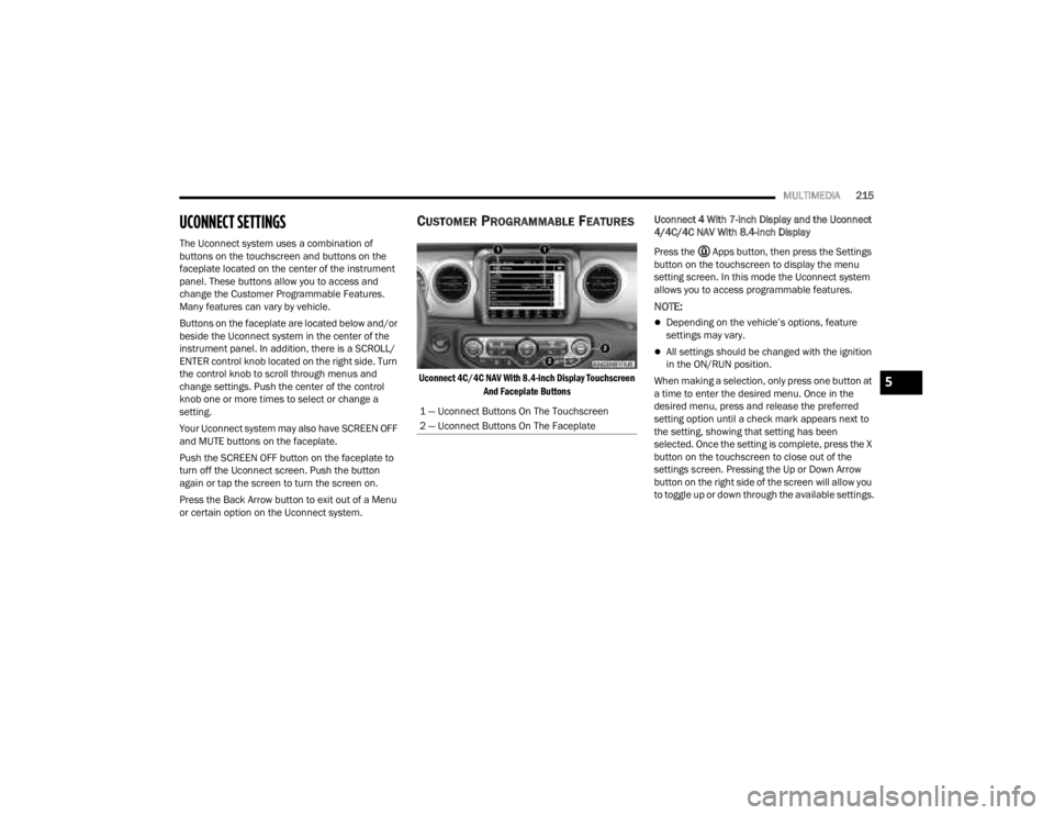
CUSTOMER PROGRAMMABLE FEATURES
Uconnect 4C/4C NAV With 8.4-inch Display Touchscreen
And Faceplate Buttons
Uconnect 4 With 7-inch Display and the Uconnect
4/4C/4C NAV With 8.4-inch Display
Press the Apps button, then press the Settings
button on the touchscreen to display the menu
setting screen. In this mode the Uconnect system
allows you to access programmable features.
NOTE:
Depending on the vehicle’s options, feature
settings may vary.
All settings should be changed with the ignition
in the ON/RUN position.
When making a selection, only press one button at
a time to enter the desired menu. Once in the
desired menu, press and release the preferred
setting option until a check mark appears next to
the setting, showing that setting has been
selected. Once the setting is complete, press the X
button on the touchscreen to close out of the
settings screen. Pressing the Up or Down Arrow
button on the right side of the screen will allow you
to toggle up or down through the available settings.
1 — Uconnect Buttons On The Touchscreen
2 — Uconnect Buttons On The Faceplate
5
23_JT_OM_EN_USC_t.book Page 215
Page 265 of 448
MULTIMEDIA263
(Continued)
Automatic SOS — If Equipped
Automatic SOS is a hands-free safety service that
can immediately connect you with help in the event
that your vehicle’s airbags deploy. After an
accident, a live agent will contact you through the
Uconnect system and alert emergency services.
NOTE:An active SiriusXM Guardian™ subscription is
required for this feature to function.
After a crash where the airbags deploy:
1. Automatic SOS will initiate a call with an agent.
2. An agent will receive the call and confirm the location of the emergency.
3. If needed, the agent will request the assistance of emergency services.
4. First responders will arrive on scene. The agent will remain on the call until emergency
services arrive.
NOTE:
Agents are available 24/7 to assist you in the
case of an emergency.
On your behalf, agents are able to notify family
members about the collision.
Agents can brief first responders of the situation
before they arrive on scene.
WARNING!
Never place anything on or near the vehicle’s
LTE (voice/data) or 4G (data) and GPS
antennas. You could prevent LTE (voice/data)
or 4G (data) and GPS signal reception, which
can prevent your vehicle from placing an
emergency call.
Do not add any aftermarket electrical equip -
ment to the vehicle’s electrical system. This
may prevent your vehicle from sending a
signal to initiate an emergency call. To avoid
interference that can cause the SOS Call
system to fail, never add aftermarket equip -
ment (e.g., two-way mobile radio, CB radio,
data recorder, etc.) to your vehicle’s electrical
system or modify the antennas on your
vehicle. IF YOUR VEHICLE LOSES POWER FOR
ANY REASON (INCLUDING DURING OR AFTER
AN ACCIDENT), NEITHER THE VEHICLE
BRANDED APPS NOR THE SIRIUSXM
GUARDIAN™ CONNECTED SERVICES WILL
OPERATE.
The Occupant Restraint Controller (ORC) turns
on the Air Bag Warning Light on the instru -
ment panel if a malfunction in any part of the
air bag system is detected. If the Air Bag
Warning Light is illuminated, the air bag
system may not be working properly and the
SOS Call system may not be able to send a
signal to the SiriusXM Guardian™ Customer
Care center. If the Air Bag Warning Light is illu -
minated, have an authorized dealer service
your vehicle immediately.
Ignoring the Rearview Mirror Light could mean
you will not have SOS Call services if needed.
If the Rearview Mirror Light is illuminated,
have an authorized dealer service the SOS
Call system immediately.
If anyone in the vehicle could be in danger
(e.g., fire or smoke is visible, dangerous road
conditions or location), do not wait for voice
contact from a SiriusXM Guardian™ Customer
Care agent. All occupants should exit the
vehicle immediately and move to a safe loca -
tion.
Failure to perform scheduled maintenance
and regular inspection of your vehicle may
result in vehicle damage, accident or injury.
WARNING!
5
23_JT_OM_EN_USC_t.book Page 263
Page 308 of 448
306SAFETY
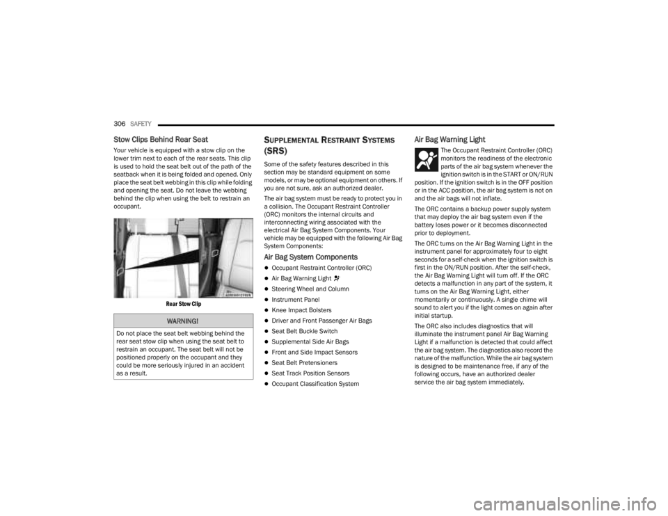
Stow Clips Behind Rear Seat
Your vehicle is equipped with a stow clip on the
lower trim next to each of the rear seats. This clip
is used to hold the seat belt out of the path of the
seatback when it is being folded and opened. Only
place the seat belt webbing in this clip while folding
and opening the seat. Do not leave the webbing
behind the clip when using the belt to restrain an
occupant.
Rear Stow Clip
SUPPLEMENTAL RESTRAINT SYSTEMS
(SRS)
Some of the safety features described in this
section may be standard equipment on some
models, or may be optional equipment on others. If
you are not sure, ask an authorized dealer.
The air bag system must be ready to protect you in
a collision. The Occupant Restraint Controller
(ORC) monitors the internal circuits and
interconnecting wiring associated with the
electrical Air Bag System Components. Your
vehicle may be equipped with the following Air Bag
System Components:
Air Bag System Components
Occupant Restraint Controller (ORC)
Air Bag Warning Light
Steering Wheel and Column
Instrument Panel
Knee Impact Bolsters
Driver and Front Passenger Air Bags
Seat Belt Buckle Switch
Supplemental Side Air Bags
Front and Side Impact Sensors
Seat Belt Pretensioners
Seat Track Position Sensors
Occupant Classification System
Air Bag Warning Light
The Occupant Restraint Controller (ORC)
monitors the readiness of the electronic
parts of the air bag system whenever the
ignition switch is in the START or ON/RUN
position. If the ignition switch is in the OFF position
or in the ACC position, the air bag system is not on
and the air bags will not inflate.
The ORC contains a backup power supply system
that may deploy the air bag system even if the
battery loses power or it becomes disconnected
prior to deployment.
The ORC turns on the Air Bag Warning Light in the
instrument panel for approximately four to eight
seconds for a self-check when the ignition switch is
first in the ON/RUN position. After the self-check,
the Air Bag Warning Light will turn off. If the ORC
detects a malfunction in any part of the system, it
turns on the Air Bag Warning Light, either
momentarily or continuously. A single chime will
sound to alert you if the light comes on again after
initial startup.
The ORC also includes diagnostics that will
illuminate the instrument panel Air Bag Warning
Light if a malfunction is detected that could affect
the air bag system. The diagnostics also record the
nature of the malfunction. While the air bag system
is designed to be maintenance free, if any of the
following occurs, have an authorized dealer
service the air bag system immediately.
WARNING!
Do not place the seat belt webbing behind the
rear seat stow clip when using the seat belt to
restrain an occupant. The seat belt will not be
positioned properly on the occupant and they
could be more seriously injured in an accident
as a result.
23_JT_OM_EN_USC_t.book Page 306
Page 309 of 448
SAFETY307
(Continued)
The Air Bag Warning Light does not come on
during the four to eight seconds when the igni -
tion switch is first in the ON/RUN position.
The Air Bag Warning Light remains on after the
four to eight-second interval.
The Air Bag Warning Light comes on intermit -
tently or remains on while driving.
NOTE:If the speedometer, tachometer, or any engine
related gauges are not working, the Occupant
Restraint Controller (ORC) may also be disabled. In
this condition the air bags may not be ready to
inflate for your protection. Have an authorized
dealer service the air bag system immediately.
Redundant Air Bag Warning Light
If a fault with the Air Bag Warning Light is
detected, which could affect the
Supplemental Restraint System (SRS),
the Redundant Air Bag Warning Light will
illuminate on the instrument panel. The
Redundant Air Bag Warning Light will stay on until
the fault is cleared. In addition, a single chime will
sound to alert you that the Redundant Air Bag
Warning Light has come on and a fault has been
detected. If the Redundant Air Bag Warning Light
comes on intermittently or remains on while driving
have an authorized dealer service the vehicle
immediately.
See Ú page 132 for more information regarding
the Redundant Air Bag Warning Light.
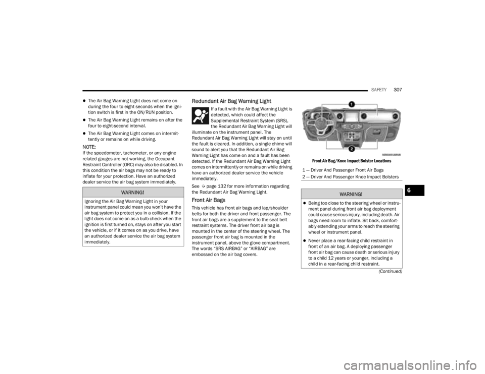
Front Air Bags
This vehicle has front air bags and lap/shoulder
belts for both the driver and front passenger. The
front air bags are a supplement to the seat belt
restraint systems. The driver front air bag is
mounted in the center of the steering wheel. The
passenger front air bag is mounted in the
instrument panel, above the glove compartment.
The words “SRS AIRBAG” or “AIRBAG” are
embossed on the air bag covers.
Front Air Bag/Knee Impact Bolster Locations
WARNING!
Ignoring the Air Bag Warning Light in your
instrument panel could mean you won’t have the
air bag system to protect you in a collision. If the
light does not come on as a bulb check when the
ignition is first turned on, stays on after you start
the vehicle, or if it comes on as you drive, have
an authorized dealer service the air bag system
immediately.
1 — Driver And Passenger Front Air Bags
2 — Driver And Passenger Knee Impact Bolsters
WARNING!
Being too close to the steering wheel or instru
-
ment panel during front air bag deployment
could cause serious injury, including death. Air
bags need room to inflate. Sit back, comfort -
ably extending your arms to reach the steering
wheel or instrument panel.
Never place a rear-facing child restraint in
front of an air bag. A deploying passenger
front air bag can cause death or serious injury
to a child 12 years or younger, including a
child in a rear-facing child restraint.
6
23_JT_OM_EN_USC_t.book Page 307