ABS JEEP GLADIATOR 2023 Owners Manual
[x] Cancel search | Manufacturer: JEEP, Model Year: 2023, Model line: GLADIATOR, Model: JEEP GLADIATOR 2023Pages: 448, PDF Size: 17.37 MB
Page 8 of 448
6
CONNECTED VEHICLE SERVICES —
IF EQUIPPED ........................................................ 258 Is My Vehicle Connected?............................. 258
Introduction To Connected Vehicle
Services ......................................................... 258
Getting Started With Connected Vehicle
Services ......................................................... 260
Using SiriusXM Guardian™ .......................... 261
Manage My SiriusXM Guardian™ Account .. 272
CONNECTED SERVICES FAQS ........................... 272
Connected Services SOS FAQs —
If Equipped .................................................... 272
Connected Services Remote Door Lock/
Unlock FAQs .................................................. 272
Connected Services Roadside Assistance
FAQs .............................................................. 272
Connected Services Send & Go FAQs —
If Equipped .................................................... 273
Connected Services Vehicle Finder FAQs ... 273
Connected Services Stolen Vehicle
Assistance FAQs — If Equipped ................... 273
Connected Services Remote Vehicle
Start FAQs ..................................................... 274
Connected Services Remote Horn &
Lights FAQs .................................................... 274
Connected Services Account
FAQs — If Equipped ....................................... 274
Data Collection & Privacy.............................. 276 RADIO OPERATION AND MOBILE PHONES ..... 276
Regulatory And Safety Information .............. 277
OFF-ROAD PAGES — IF EQUIPPED.................... 277
Off-Road Pages Status Bar ........................... 277Drivetrain ....................................................... 278
Accessory Gauge ........................................... 278Pitch & Roll ................................................... 278
SAFETY
SAFETY FEATURES .............................................. 279
Anti-Lock Brake System (ABS) ..................... 279
Electronic Brake Control (EBC) System ...... 280
AUXILIARY DRIVING SYSTEMS.......................... 287
Blind Spot Monitoring (BSM) —
If Equipped .................................................... 287
Forward Collision Warning (FCW) With
Mitigation — If Equipped ............................... 291
Tire Pressure Monitoring System (TPMS) .... 294
OCCUPANT RESTRAINT SYSTEMS ................... 299
Occupant Restraint Systems Features ....... 299
Important Safety Precautions ...................... 299Seat Belt Systems ........................................ 300Supplemental Restraint Systems (SRS) ...... 306Child Restraints ............................................. 318 SAFETY TIPS ......................................................... 328
Transporting Passengers.............................. 328
Transporting Pets .......................................... 329Connected Vehicles ...................................... 329
Safety Checks You Should Make Inside
The Vehicle ................................................... 329
Periodic Safety Checks You Should Make
Outside The Vehicle ...................................... 330
Exhaust Gas................................................... 331
Carbon Monoxide Warnings ......................... 331
IN CASE OF EMERGENCY
HAZARD WARNING FLASHERS ......................... 332
ASSIST AND SOS SYSTEM — IF EQUIPPED ...... 332
JACKING AND TIRE CHANGING
S
.................. 335
Preparations For Jacking ............................. 336 Jack Location ................................................ 336
Spare Tire Location And Removal ............... 338
Jacking Instructions ...................................... 339
To Stow The Flat Or Spare ............................ 342
Reinstalling The Jack And Tools ................... 343
JUMP STARTING ................................................. 343
Preparations For Jump Start ........................ 344Jump Starting Procedure .............................. 345
REFUELING IN EMERGENCY – IF EQUIPPED .. 346
IF YOUR ENGINE OVERHEATS ............................ 347
MANUAL PARK RELEASE ................................... 348
FREEING A STUCK VEHICLE .............................. 349
23_JT_OM_EN_USC_t.book Page 6
Page 14 of 448
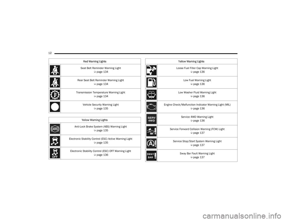
12 Seat Belt Reminder Warning Light Úpage 134
Rear Seat Belt Reminder Warning Light Úpage 134
Transmission Temperature Warning Light Úpage 134
Vehicle Security Warning Light Úpage 135
Yellow Warning Lights
Anti-Lock Brake System (ABS) Warning Light Úpage 135
Electronic Stability Control (ESC) Active Warning Light Úpage 135
Electronic Stability Control (ESC) OFF Warning Light Úpage 136
Red Warning Lights
Loose Fuel Filler Cap Warning Light
Úpage 136
Low Fuel Warning Light Úpage 136
Low Washer Fluid Warning Light Úpage 136
Engine Check/Malfunction Indicator Warning Light (MIL) Úpage 136
Service 4WD Warning Light Úpage 136
Service Forward Collision Warning (FCW) Light Úpage 137
Service Stop/Start System Warning Light Úpage 137
Sway Bar Fault Warning Light Úpage 137
Yellow Warning Lights
23_JT_OM_EN_USC_t.book Page 12
Page 19 of 448
GETTING TO KNOW YOUR VEHICLE17
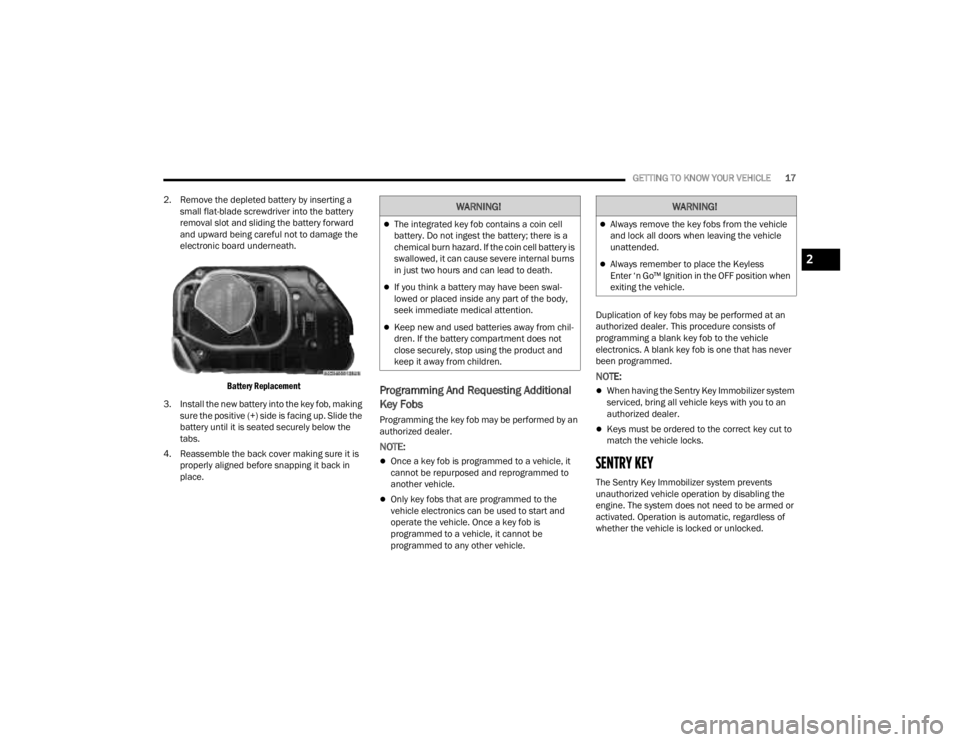
2. Remove the depleted battery by inserting a small flat-blade screwdriver into the battery
removal slot and sliding the battery forward
and upward being careful not to damage the
electronic board underneath.
Battery Replacement
3. Install the new battery into the key fob, making sure the positive (+) side is facing up. Slide the
battery until it is seated securely below the
tabs.
4. Reassemble the back cover making sure it is properly aligned before snapping it back in
place.
Programming And Requesting Additional
Key Fobs
Programming the key fob may be performed by an
authorized dealer.
NOTE:
Once a key fob is programmed to a vehicle, it
cannot be repurposed and reprogrammed to
another vehicle.
Only key fobs that are programmed to the
vehicle electronics can be used to start and
operate the vehicle. Once a key fob is
programmed to a vehicle, it cannot be
programmed to any other vehicle. Duplication of key fobs may be performed at an
authorized dealer. This procedure consists of
programming a blank key fob to the vehicle
electronics. A blank key fob is one that has never
been programmed.
NOTE:
When having the Sentry Key Immobilizer system
serviced, bring all vehicle keys with you to an
authorized dealer.
Keys must be ordered to the correct key cut to
match the vehicle locks.
SENTRY KEY
The Sentry Key Immobilizer system prevents
unauthorized vehicle operation by disabling the
engine. The system does not need to be armed or
activated. Operation is automatic, regardless of
whether the vehicle is locked or unlocked.
WARNING!
The integrated key fob contains a coin cell
battery. Do not ingest the battery; there is a
chemical burn hazard. If the coin cell battery is
swallowed, it can cause severe internal burns
in just two hours and can lead to death.
If you think a battery may have been swal-
lowed or placed inside any part of the body,
seek immediate medical attention.
Keep new and used batteries away from chil
-
dren. If the battery compartment does not
close securely, stop using the product and
keep it away from children.
WARNING!
Always remove the key fobs from the vehicle
and lock all doors when leaving the vehicle
unattended.
Always remember to place the Keyless
Enter ‘n Go™ Ignition in the OFF position when
exiting the vehicle.2
23_JT_OM_EN_USC_t.book Page 17
Page 31 of 448
GETTING TO KNOW YOUR VEHICLE29
To remove the front doors, proceed as follows:
1. Roll down the glass window to prevent any damage.
2. Remove the hinge pin nut from the upper and lower outside hinges (using a #T50 Torx head
driver).
NOTE:The hinge pin nuts can be stowed in the Fastener
Bin located under the rear seat.
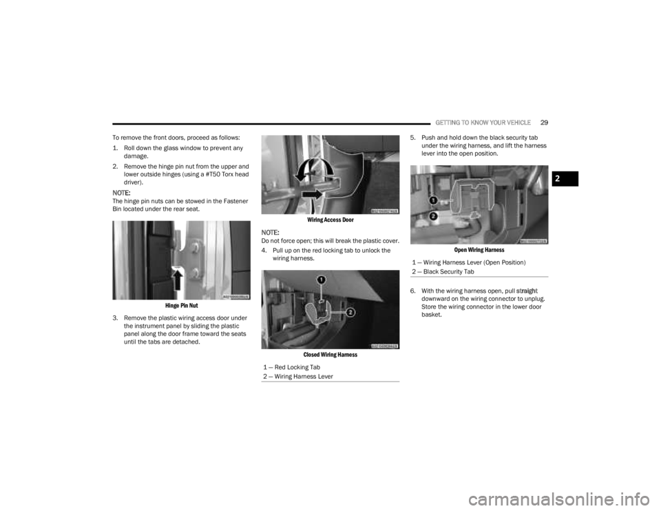
Hinge Pin Nut
3. Remove the plastic wiring access door under the instrument panel by sliding the plastic
panel along the door frame toward the seats
until the tabs are detached.
Wiring Access Door
NOTE:Do not force open; this will break the plastic cover.
4. Pull up on the red locking tab to unlock the
wiring harness.
Closed Wiring Harness
5. Push and hold down the black security tab
under the wiring harness, and lift the harness
lever into the open position.
Open Wiring Harness
6. With the wiring harness open, pull straight
downward on the wiring connector to unplug.
Store the wiring connector in the lower door
basket.
1 — Red Locking Tab
2 — Wiring Harness Lever
1 — Wiring Harness Lever (Open Position)
2 — Black Security Tab
2
23_JT_OM_EN_USC_t.book Page 29
Page 87 of 448
GETTING TO KNOW YOUR VEHICLE85
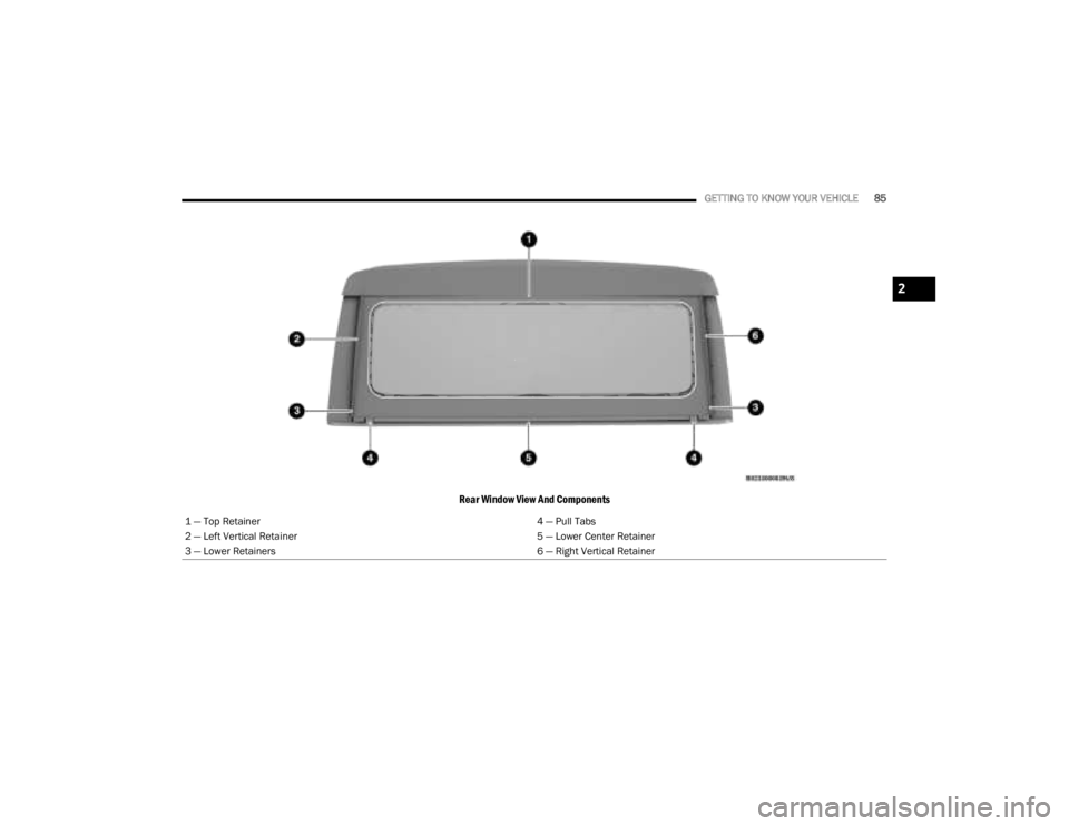
Rear Window View And Components
1 — Top Retainer 4 — Pull Tabs
2 — Left Vertical Retainer 5 — Lower Center Retainer
3 — Lower Retainers 6 — Right Vertical Retainer
2
23_JT_OM_EN_USC_t.book Page 85
Page 134 of 448
132GETTING TO KNOW YOUR INSTRUMENT PANEL
WARNING LIGHTS AND MESSAGES
The warning/indicator lights will illuminate in the
instrument panel together with a dedicated
message and/or acoustic signal when applicable.
These indications are indicative and precautionary
and as such must not be considered as exhaustive
and/or alternative to the information contained in
the Owner’s Manual, which you are advised to read
carefully in all cases. Always refer to the
information in this chapter in the event of a failure
indication. All active telltales will display first if
applicable. The system check menu may appear
different based upon equipment options and
current vehicle status. Some telltales are optional
and may not appear.
RED WARNING LIGHTS
Air Bag Warning Light
This warning light will illuminate to
indicate a fault with the air bag, and will
turn on for four to eight seconds as a bulb
check when the ignition is placed in the
ON/RUN or ACC/ON/RUN position. This light will
illuminate with a single chime when a fault with the
air bag has been detected, it will stay on until the
fault is cleared. If the light is not on during startup,
stay on, or turns on while driving, have the system
inspected at an authorized dealer as soon as
possible.
Brake Warning Light
This warning light monitors various brake
functions, including brake fluid level and
parking brake application. If the brake
light turns on it may indicate that the
parking brake is applied, that the brake fluid level
is low, or that there is a problem with the Anti-Lock
Brake System reservoir.
If the light remains on when the parking brake has
been disengaged, and the fluid level is at the full
mark on the master cylinder reservoir, it indicates
a possible brake hydraulic system malfunction or
that a problem with the Brake Booster has been
detected by the Anti-Lock Brake System (ABS) /
Electronic Stability Control (ESC) system. In this
case, the light will remain on until the condition has
been corrected. If the problem is related to the
brake booster, the ABS pump will run when
applying the brake, and a brake pedal pulsation
may be felt during each stop.
The dual brake system provides a reserve braking
capacity in the event of a failure to a portion of the
hydraulic system. A leak in either half of the dual
brake system is indicated by the Brake Warning
Light, which will turn on when the brake fluid level
in the master cylinder has dropped below a
specified level.
The light will remain on until the cause is corrected.
NOTE:The light may flash momentarily during sharp
cornering maneuvers, which change fluid level
conditions. The vehicle should have service
performed, and the brake fluid level checked.
If brake failure is indicated, immediate repair is
necessary.
Vehicles equipped with the Anti-Lock Brake System
(ABS) are also equipped with Electronic Brake
Force Distribution (EBD). In the event of an EBD
failure, the Brake Warning Light will turn on along
with the ABS Light. Immediate repair to the ABS
system is required.
Operation of the Brake Warning Light can be
checked by turning the ignition switch from the OFF
position to the ON/RUN position. The light should
illuminate for approximately two seconds. The light
should then turn off unless the parking brake is
applied or a brake fault is detected. If the light does
not illuminate, have the light inspected by an
authorized dealer.
WARNING!
Driving a vehicle with the red brake light on is
dangerous. Part of the brake system may have
failed. It will take longer to stop the vehicle. You
could have a collision. Have the vehicle checked
immediately.
23_JT_OM_EN_USC_t.book Page 132
Page 137 of 448
GETTING TO KNOW YOUR INSTRUMENT PANEL135
Vehicle Security Warning Light —
If Equipped
This light will flash at a fast rate for
approximately 15 seconds when the
vehicle security system is arming, and
then will flash slowly until the vehicle is
disarmed.
YELLOW WARNING LIGHTS
Anti-Lock Brake System (ABS) Warning
Light
This warning light monitors the ABS. The
light will turn on when the ignition is
placed in the ON/RUN or ACC/ON/RUN
position and may stay on for as long as
four seconds.
If the ABS light remains on or turns on while
driving, then the Anti-Lock portion of the brake
system is not functioning and service is required as
soon as possible. However, the conventional brake
system will continue to operate normally,
assuming the Brake Warning Light is not also on.
If the ABS light does not turn on when the ignition
is placed in the ON/RUN or ACC/ON/RUN position,
have the brake system inspected by an authorized
dealer.
Electronic Stability Control (ESC) Active
Warning Light — If Equipped
This warning light will indicate when the
Electronic Stability Control system is
Active. The ESC Indicator Light in the
instrument cluster will come on when the
ignition is placed in the ON/RUN or ACC/ON/RUN
position, and when ESC is activated. It should go
out with the engine running. If the ESC Indicator
Light comes on continuously with the engine
running, a malfunction has been detected in the
ESC system. If this warning light remains on after
several ignition cycles, and the vehicle has been
driven several miles (kilometers) at speeds greater
than 30 mph (48 km/h), see an authorized dealer
as soon as possible to have the problem
diagnosed and corrected.
The ESC OFF Indicator Light and the ESC Indi -
cator Light come on momentarily each time the
ignition is placed in the ON/RUN or ACC/ON/
RUN position.
The ESC system will make buzzing or clicking
sounds when it is active. This is normal; the
sounds will stop when ESC becomes inactive.
This light will come on when the vehicle is in an
ESC event.
WARNING!
If you continue operating the vehicle when the
Transmission Temperature Warning Light is illumi -
nated you could cause the fluid to boil over, come
in contact with hot engine or exhaust components
and cause a fire. If you continue to operate the
vehicle when the CLUTCH HOT message is dis -
played or Transmission Temperature Warning
Light is illuminated, you could cause the clutch to
overheat and cause a fire.
CAUTION!
Continuous driving with the Transmission Tem -
perature Warning Light illuminated will eventu -
ally cause severe transmission damage or
transmission failure. If you continue to operate
the vehicle when the CLUTCH HOT message is
displayed or Transmission Temperature Warning
Light is illuminated, you could cause the clutch
to overheat and cause severe clutch damage,
transmission damage or failure.
3
23_JT_OM_EN_USC_t.book Page 135
Page 180 of 448
178STARTING AND OPERATING
Pushing the Fixed Speed Cruise Control on/off
button will result in turning on (changing to) Fixed
Speed Cruise Control mode.
If ACC is set when the vehicle speed is below
20 mph (32 km/h), the set speed will default to
20 mph (32 km/h).
NOTE:Fixed Speed Cruise Control cannot be set below
20 mph (32 km/h).
If either system is set when the vehicle speed is
above 20 mph (32 km/h), the set speed shall be
the current speed of the vehicle.
NOTE:
Keeping your foot on the accelerator pedal can
cause the vehicle to continue to accelerate
beyond the set speed. If this occurs, the message “DRIVER OVERRIDE” will display in the
instrument cluster display.
If you continue to accelerate beyond the set
speed while ACC is enabled, the system will not
be controlling the distance between your vehicle
and the vehicle ahead. The vehicle speed will
only be determined by the position of the accel-
erator pedal.
To Cancel
The following conditions cancel the ACC or Fixed
Speed Cruise Control systems:
The brake pedal is applied
The CANC (cancel) button is pushed
The Anti-Lock Brake system (ABS) activates
The gear selector is removed from the DRIVE
position
The braking temperature exceeds normal range
(overheated)
The Electronic Stability Control/Traction Control
system (ESC/TCS) activates
The vehicle parking brake is applied
A Trailer Sway Control (TSC) event occurs
The driver switches ESC to Full Off mode
The vehicle speed is less than 15 mph (24 km/h)
(manual transmission only)
The clutch is pressed for more than 10 seconds
(manual transmission only)
The vehicle is placed in NEUTRAL for more than
10 seconds (manual transmission only)
The driver shifts to FIRST gear (manual trans
-
mission only)
Vehicle is operating at a low RPM (manual trans -
mission only)
When Off Road+ (if equipped) is enabled
The following conditions will only cancel the ACC
system:
Driver seat belt is unbuckled at low speeds
Driver door is opened at low speeds
To Turn Off
The system will turn off and clear the set speed in
memory if:
The Adaptive Cruise Control (ACC) on/off button
is pushed
The Fixed Speed Cruise Control on/off button is
pushed
The ignition is placed in the OFF position
4WD Low is engaged
To Resume
If there is a set speed in memory push the RES
(resume) button and then remove your foot from
the accelerator pedal. The instrument cluster
display will display the last set speed.
WARNING!
In Fixed Speed Cruise Control mode (ACC not
enabled), the system will not react to vehicles
ahead. In addition, the proximity warning does
not activate and no alarm will sound even if you
are too close to the vehicle ahead since neither
the presence of the vehicle ahead nor the
vehicle-to-vehicle distance is detected. Be sure
to maintain a safe distance between your vehicle
and the vehicle ahead. Always be aware which
mode is selected.
23_JT_OM_EN_USC_t.book Page 178
Page 197 of 448
STARTING AND OPERATING195
(Continued)
The DEF gauge may also not immediately
update after a refill if the temperature of the
DEF fluid is below 12°F (-11°C). The DEF
line heater will possibly warm up the DEF
fluid and allow the gauge to update after a
period of run time. Under very cold condi -
tions, it is possible that the gauge may not
reflect the new fill level for several drives.
Excessive overfilling of the DEF tank can
result in a MIL lamp/fault code and inaccu-
rate level readings.
Refilling With Nozzles
You can fill up at any DEF distributor.
Proceed as follows:
Insert the DEF nozzle in the filler, start
refilling and stop refilling at the first shut-off
(the shut-off indicates that the DEF tank is
full). Do not proceed with the refilling, to
prevent spillage of DEF.
Extract the nozzle.
Refilling With Containers
Proceed as follows:
Check the expiration date.
Read the advice for use on the label before
pouring the content of the bottle into the
DEF tank.
If systems which cannot be screwed in
(e.g. tanks) are used for refilling, after the
indication appears on the instrument panel
display Úpage 121 fill the DEF tank with no
more than 2 gal (8 L).
If containers which can be screwed to the
filler are used, the reservoir is full when the
DEF level in the container stops pouring out.
Do not proceed further.
3. Stop filling the DEF tank immediately when any of the following happen: DEF stops flowing
from the fill bottle into the DEF fill inlet, DEF
splashes out the fill inlet, or a DEF pump
nozzle automatically shuts off.
4. Reinstall cap onto DEF fill inlet.
VEHICLE LOADING
CERTIFICATION LABEL
As required by National Highway Traffic Safety
Administration regulations, your vehicle has a
certification label affixed to the driver's side door or
pillar.
CAUTION!
To avoid DEF spillage, and possible damage to
the DEF tank from overfilling, do not “top off”
the DEF tank after filling.
DO NOT OVERFILL. DEF will freeze below 12ºF
(-11ºC). The DEF system is designed to work in
temperatures below the DEF freezing point,
however, if the tank is overfilled and freezes,
the system could be damaged.
When DEF is spilled, clean the area immedi -
ately with water and use an absorbent mate -
rial to soak up the spills on the ground.
Do not attempt to start your engine if DEF is
accidentally added to the diesel fuel tank as it
can result in severe damage to your engine,
including but not limited to failure of the fuel
pump and injectors.
Never add anything other than DEF to the tank
– especially any form of hydrocarbon such as
diesel fuel, fuel system additives, gasoline, or
any other petroleum-based product. Even a
very small amount of these, less than
100 parts per million or less than 1 oz. per
78 gal (295 L) will contaminate the entire DEF
system and will require replacement. If
owners use a container, funnel or nozzle when
refilling the tank, it should either be new or
one that is has only been used for adding DEF.
Mopar® provides an attachable nozzle with its
DEF for this purpose.
CAUTION!
4
23_JT_OM_EN_USC_t.book Page 195
Page 240 of 448
238MULTIMEDIA
FAVORITES
Press the Favorites button on the touchscreen to
activate the favorites menu, which will time out
within 20 seconds in absence of user interaction.
You can exit the Favorites Menu by a press of the X
button.
The Favorites feature enables you to set a favorite
artist or song that is currently playing. The radio
then uses this information to alert you when either
the favorite artist or song is being played at any
time by any of the SiriusXM® Channels.
The maximum number of favorites that can be
stored in the Radio is 50.
Favorite Artist: While the song is playing, to set a
favorite artist, press the Favorites button on the
touchscreen and then the Favorite Artist button on
the touchscreen.
Favorite Song: While the song is playing, to set a
favorite song, press the Favorites button on the
touchscreen and then the Favorite Song button on
the touchscreen.
BROWSE IN SXM
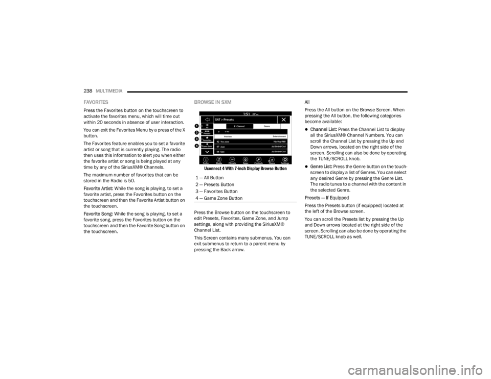
Uconnect 4 With 7-inch Display Browse Button
Press the Browse button on the touchscreen to
edit Presets, Favorites, Game Zone, and Jump
settings, along with providing the SiriusXM®
Channel List.
This Screen contains many submenus. You can
exit submenus to return to a parent menu by
pressing the Back arrow. All
Press the All button on the Browse Screen. When
pressing the All button, the following categories
become available:
Channel List:
Press the Channel List to display
all the SiriusXM® Channel Numbers. You can
scroll the Channel List by pressing the Up and
Down arrows, located on the right side of the
screen. Scrolling can also be done by operating
the TUNE/SCROLL knob.
Genre List: Press the Genre button on the touch -
screen to display a list of Genres. You can select
any desired Genre by pressing the Genre List.
The radio tunes to a channel with the content in
the selected Genre.
Presets — If Equipped
Press the Presets button (if equipped) located at
the left of the Browse screen.
You can scroll the Presets list by pressing the Up
and Down arrows located at the right side of the
screen. Scrolling can also be done by operating the
TUNE/SCROLL knob as well.
1 — All Button
2 — Presets Button
3 — Favorites Button
4 — Game Zone Button
23_JT_OM_EN_USC_t.book Page 238