reset JEEP GLADIATOR 2023 Owners Manual
[x] Cancel search | Manufacturer: JEEP, Model Year: 2023, Model line: GLADIATOR, Model: JEEP GLADIATOR 2023Pages: 448, PDF Size: 17.37 MB
Page 6 of 448

4
INSTRUMENT CLUSTER DISPLAY ...................... 121 Instrument Cluster Display Location And
Controls .......................................................... 122
Oil Life Reset — If Equipped
S
................... 122
Off Road+ Display — If Equipped .................. 123
Instrument Cluster Display Selectable
Items .............................................................. 123
Instrument Cluster Display Menu Items ...... 124
Battery Saver On, Battery Saver Mode
Message, And Electrical Load Reduction
Actions
(If Equipped) .................................................. 127
Diesel Displays .............................................. 128 Diesel Particulate Filter (DPF) Messages .... 128Fuel System Messages ................................. 130
WARNING LIGHTS AND MESSAGES ................. 132
Red Warning Lights ....................................... 132
Yellow Warning Lights ................................... 135Yellow Indicator Lights .................................. 138
Green Indicator Lights................................... 139White Indicator Lights ................................... 140Blue Indicator Lights ..................................... 141
ONBOARD DIAGNOSTIC SYSTEM — OBD II ...... 141
Onboard Diagnostic System
(OBD II) Cybersecurity ................................... 142
EMISSIONS INSPECTION AND MAINTENANCE
PROGRAMS .......................................................... 142
STARTING AND OPERATING
STARTING THE ENGINE — GASOLINE ENGINE
(IF EQUIPPED) ...................................................... 144
Manual Transmission — If Equipped ........... 144Automatic Transmission —
If Equipped .................................................... 144
Normal Starting ............................................ 144
AutoPark ........................................................ 145Extreme Cold Weather
(Below –22°F Or −30°C) ............................ 146
Extended Park Starting ................................. 146
If Engine Fails To Start ................................. 147
After Starting ................................................. 147
STARTING THE ENGINE — DIESEL ENGINE
(IF EQUIPPED) ...................................................... 147
Automatic Transmission ............................... 148
Extreme Cold Weather .................................. 148
Normal Starting ............................................. 148Starting Fluids ............................................... 149
NORMAL OPERATION — DIESEL ENGINE ......... 149
Cold Weather Precautions ............................ 149
Engine Idling .................................................. 150
Stopping The Engine ..................................... 150
Cooling System Tips — Automatic
Transmission ................................................. 151
ENGINE BREAK-IN RECOMMENDATIONS —
GASOLINE ENGINE (IF EQUIPPED) ................... 151 ENGINE BREAK-IN RECOMMENDATIONS —
DIESEL ENGINE (IF EQUIPPED) .......................... 152
PARKING BRAKE ................................................. 152
MANUAL TRANSMISSION — IF EQUIPPED ....... 153
Shifting........................................................... 154
Downshifting.................................................. 155
AUTOMATIC TRANSMISSION —
IF EQUIPPED ......................................................... 155
Ignition Park Interlock................................... 156
Brake/Transmission Shift Interlock (BTSI)
System .......................................................... 1578–Speed Automatic Transmission .............. 157
Gear Ranges .................................................. 157
FOUR–WHEEL DRIVE OPERATION ................... 161
Four-Position Transfer Case —
If Equipped .................................................... 161
Five-Position Transfer Case —
If Equipped .................................................... 163
Trac-Lok Rear Axle — If Equipped ................ 165Axle Lock (Tru-Lok) Front And Rear —
If Equipped ................................................... 165
Axle Lock (Tru-Lok) Rear Only —
If Equipped ................................................... 166
Electronic Sway Bar Disconnect —
If Equipped ................................................... 166
OFF ROAD+ — If Equipped ............................ 168
ELECTRO-HYDRAULIC POWER STEERING ....... 168
23_JT_OM_EN_USC_t.book Page 4
Page 24 of 448
22GETTING TO KNOW YOUR VEHICLE
For more information on ATC, MTC, and climate
control settings, see Ú page 61.
NOTE:These features will stay on through the duration of
Remote Start, or until the ignition is placed in the
ON/RUN position. The climate control settings will
change if manually adjusted by the driver while the
vehicle is in remote start mode. This includes
turning the climate controls off using the OFF
button.
REMOTE START WINDSHIELD WIPER
D
E-ICER ACTIVATION — IF EQUIPPED
When Remote Start is active and the outside
ambient temperature is less than 33°F (0.6°C),
the Windshield Wiper De-Icer will activate. Exiting
Remote Start will resume previous operation. If the
Windshield Wiper De-Icer was active, the
Windshield Wiper De-Icer timer and operation will
continue.
REMOTE START CANCEL MESSAGE
The following messages will display in the
instrument cluster if the vehicle fails to remote
start or exits Remote Start prematurely:
Remote Start Canceled — Door Open
Remote Start Canceled — Hood Open
Remote Start Canceled — Fuel Low
Remote Start Canceled — Tailgate Open
Remote Start Canceled — Time Expired
Remote Start Disabled — Start Vehicle To Reset
The message will stay active until the ignition is
placed in the ON/RUN position.
REMOTE START — IF EQUIPPED (DIESEL)
This system uses the key fob to start the
engine conveniently from outside the
vehicle while still maintaining security.
The system has a range of approximately
328 ft (100 m).
Remote Start is used to defrost windows in cold
weather, and to reach a comfortable climate in all
ambient conditions before the driver enters the
vehicle.
NOTE:
The vehicle must be equipped with an auto -
matic transmission to be equipped with Remote
Start.
Obstructions between the vehicle and the key
fob may reduce this range.
The Remote Start system will wait for the Wait
To Start yellow telltale to extinguish before
cranking the engine Ú page 132. This allows
time for the engine preheat cycle to heat the
cylinder air, and is normal in cold weather.
HOW TO USE REMOTE START
Push and release the Remote Start button on the
key fob twice within five seconds. The vehicle
doors and tailgate will lock, the turn signals will
flash twice, and the horn will chirp twice. Pushing
the Remote Start button again will shut the engine
off.
NOTE:
With Remote Start, the engine will only run for
15 minutes.
Remote Start can only be used twice.
If an engine fault is present or fuel level is low,
the vehicle will start and then shut down in 10
seconds.
WARNING!
Do not start or run an engine in a closed
garage or confined area. Exhaust gas contains
carbon monoxide (CO) which is odorless and
colorless. Carbon monoxide is poisonous and
can cause serious injury or death when
inhaled.
Keep key fobs away from children. Operation
of the Remote Start system, windows, door
locks or other controls could cause serious
injury or death.
23_JT_OM_EN_USC_t.book Page 22
Page 74 of 448
72GETTING TO KNOW YOUR VEHICLE
Depending on your vehicle’s specifications, the USB
port may contain playback capabilities and will allow
you to play music from your smartphone device or
USB devices through your vehicle’s sound system.
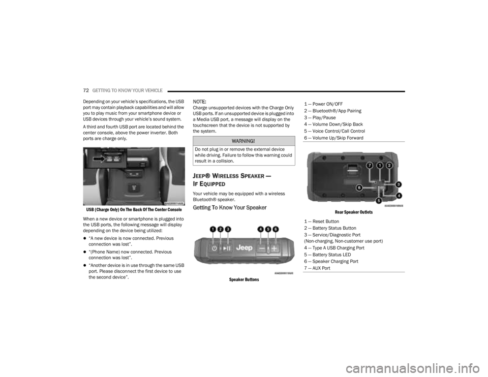
A third and fourth USB port are located behind the
center console, above the power inverter. Both
ports are charge only.
USB (Charge Only) On The Back Of The Center Console
When a new device or smartphone is plugged into
the USB ports, the following message will display
depending on the device being utilized:
“A new device is now connected. Previous
connection was lost”.
“(Phone Name) now connected. Previous
connection was lost”.
“Another device is in use through the same USB
port. Please disconnect the first device to use
the second device”.
NOTE:Charge unsupported devices with the Charge Only
USB ports. If an unsupported device is plugged into
a Media USB port, a message will display on the
touchscreen that the device is not supported by
the system.
JEEP® WIRELESS SPEAKER —
I
F EQUIPPED
Your vehicle may be equipped with a wireless
Bluetooth® speaker.
Getting To Know Your Speaker
Speaker Buttons Rear Speaker Outlets
WARNING!
Do not plug in or remove the external device
while driving. Failure to follow this warning could
result in a collision.
1 — Power ON/OFF
2 — Bluetooth®/App Pairing
3 — Play/Pause
4 — Volume Down/Skip Back
5 — Voice Control/Call Control
6 — Volume Up/Skip Forward
1 — Reset Button
2 — Battery Status Button
3 — Service/Diagnostic Port
(Non-charging, Non-customer use port)
4 — Type A USB Charging Port
5 — Battery Status LED
6 — Speaker Charging Port
7 — AUX Port
23_JT_OM_EN_USC_t.book Page 72
Page 77 of 448
GETTING TO KNOW YOUR VEHICLE75
Phone & Bluetooth® Pairing
A feature of the Jeep® wireless speaker is the
ability for the Jeep® wireless speaker to connect to
devices using Bluetooth®. Follow these simple
steps to connect a Bluetooth®-enabled device to
the Jeep® wireless speaker:
1. Press and hold the power button for 2-3 sec-
onds to turn the Jeep® wireless speaker on.
2. Turn “on” Bluetooth® for the device you desire to be connected to the Jeep® wireless
speaker. For instructions on how to turn on
and off Bluetooth® settings for the desired
device, refer to the device’s user manual.
3. When powered on, the Jeep® wireless speaker will automatically enter pairing mode.
To pair a second device, press and hold the
Bluetooth® button for 2-3 seconds, until an
audio cue is heard. Then go to the devices’
Bluetooth® settings and select “Jeep®
Speaker” from the list.
The Jeep® wireless speaker will remember the last
eight devices it has paired with.
NOTE:If the Jeep® wireless speaker is left on with an
inactive Bluetooth® connection for 30 minutes, it
will automatically turn off. The Jeep® wireless
speaker can be turned on again by pressing and
holding the power button for 2-3 seconds.
Resetting Your Jeep® Wireless Speaker
To reset the Jeep® wireless speaker to its original
factory setting, press and hold the reset button
under the back cover for 8-10 seconds.
Speakerphone
The speakerphone feature can be used by
pressing the “Voice Control” button on the Jeep®
wireless speaker. This feature can be used to
answer and end calls over the speakerphone.
Volume And Playback Control
Volume can be increased or decreased by briefly
pressing the + button or - button. When the
maximum volume is reached, an audio cue will
sound.
To skip to the next track, press and hold the
+ button. To go to the previous track, press the
- button.
Qualcomm TrueWireless™ Stereo
A feature of the Jeep® wireless speaker is being
able to pair two Jeep® wireless speakers together
for Qualcomm TrueWireless™ Stereo. This feature
allows for two Jeep® wireless speakers to play left
and right stereo sound. Below are the steps needed for Qualcomm
TrueWireless™ Stereo:
1. Push and hold the power button on both
Jeep® wireless speakers until both speakers
turn on.
2. Place both speakers into Qualcomm TrueWireless™ Stereo pairing mode. This can
be achieved by pressing and holding the
Battery Status button on both speakers until
an audio notification is heard from both
speakers.
3. Connect one of the Jeep® wireless speakers to the Bluetooth® source. Refer to previous
section “Phone & Bluetooth® Pairing” for
additional information.
4. Once the Jeep® wireless speaker is connected to the Bluetooth® device, audio will be played
from both speakers.
NOTE:While in Qualcomm TrueWireless™ Stereo mode,
the volume will not have independent speaker
control. Pushing the Up or Down Volume button on
either Jeep® wireless speaker will affect the audio
output on both, as well as volume adjustments on
the Bluetooth® device.
2
23_JT_OM_EN_USC_t.book Page 75
Page 81 of 448
GETTING TO KNOW YOUR VEHICLE79
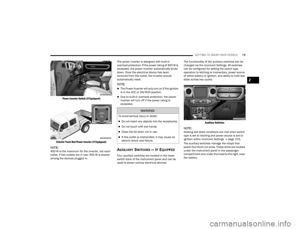
Power Inverter Switch (If Equipped)
Exterior Truck Bed Power Inverter (If Equipped)
NOTE:400 W is the maximum for the inverter, not each
outlet. If two outlets are in use, 400 W is shared
among the devices plugged in. The power inverter is designed with built-in
overload protection. If the power rating of 400 W is
exceeded, the power inverter automatically shuts
down. Once the electrical device has been
removed from the outlet, the inverter should
automatically reset.
NOTE:
The Power Inverter will only turn on if the ignition
is in the ACC or ON/RUN position.
Due to built-in overload protection, the power
inverter will turn off if the power rating is
exceeded.
AUXILIARY SWITCHES — IF EQUIPPED
Four auxiliary switches are located in the lower
switch bank of the instrument panel and can be
used to power various electrical devices.The functionality of the auxiliary switches can be
changed via the Uconnect Settings. All switches
can be configured for setting the switch type
operation to latching or momentary, power source
of either battery or ignition, and ability to hold last
state across key cycles.
Auxiliary Switches
NOTE:Holding last state conditions are met when switch
type is set to latching and power source is set to
ignition within Uconnect Settings Ú page 215.
The auxiliary switches manage the relays that
power four blunt cut wires. These wires are located
under the instrument panel in the passenger
compartment and under the hood to the right, near
the battery.
WARNING!
To avoid serious injury or death:
Do not insert any objects into the receptacles.
Do not touch with wet hands.
Close the lid when not in use.
If this outlet is mishandled, it may cause an
electric shock and failure.
2
23_JT_OM_EN_USC_t.book Page 79
Page 124 of 448
122GETTING TO KNOW YOUR INSTRUMENT PANEL
INSTRUMENT CLUSTER DISPLAY
L
OCATION AND CONTROLS
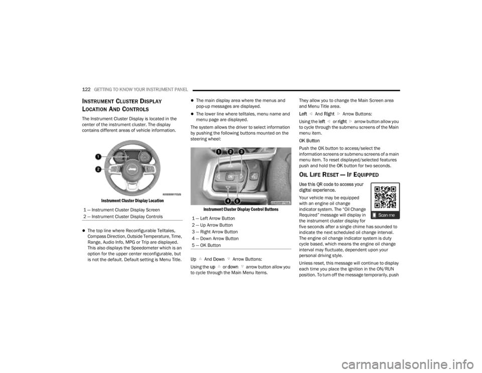
The Instrument Cluster Display is located in the
center of the instrument cluster. The display
contains different areas of vehicle information.
Instrument Cluster Display Location
The top line where Reconfigurable Telltales,
Compass Direction, Outside Temperature, Time,
Range, Audio Info, MPG or Trip are displayed.
This also displays the Speedometer which is an
option for the upper center reconfigurable, but
is not the default. Default setting is Menu Title.
The main display area where the menus and
pop-up messages are displayed.
The lower line where telltales, menu name and
menu page are displayed.
The system allows the driver to select information
by pushing the following buttons mounted on the
steering wheel:
Instrument Cluster Display Control Buttons
Up And Down Arrow Buttons:
Using the up or down arrow button allow you
to cycle through the Main Menu Items. They allow you to change the Main Screen area
and Menu Title area.
Left
And Right Arrow Buttons:
Using the left or right arrow button allow you
to cycle through the submenu screens of the Main
menu item.
OK Button
Push the OK button to access/select the
information screens or submenu screens of a main
menu item. To reset displayed/selected features
push and hold the OK button for two seconds.
OIL LIFE RESET — IF EQUIPPED
Use this QR code to access your
digital experience.
Your vehicle may be equipped
with an engine oil change
indicator system. The “Oil Change
Required” message will display in
the instrument cluster display for
five seconds after a single chime has sounded to
indicate the next scheduled oil change interval.
The engine oil change indicator system is duty
cycle based, which means the engine oil change
interval may fluctuate, dependent upon your
personal driving style.
Unless reset, this message will continue to display
each time you place the ignition in the ON/RUN
position. To turn off the message temporarily, push
1 — Instrument Cluster Display Screen
2 — Instrument Cluster Display Controls
1 — Left Arrow Button
2 — Up Arrow Button
3 — Right Arrow Button
4 — Down Arrow Button
5 — OK Button
23_JT_OM_EN_USC_t.book Page 122
Page 125 of 448
GETTING TO KNOW YOUR INSTRUMENT PANEL123
and release the OK button. To reset the oil change
indicator system (after performing the scheduled
maintenance), refer to the following procedure.
Oil Life Reset
1. Without pushing the brake pedal, place the ignition in the ON/RUN mode (do not start the
engine).
2. Navigate to "Oil Life" submenu in "Vehicle Info" in the instrument cluster display.
3. Push and hold the OK button until the gauge
resets to 100%.
Secondary Method For Oil Change Reset
Procedure
1. Without pushing the brake pedal, place the ignition in the ON/RUN position (do not start
the engine).
2. Fully press the accelerator pedal, slowly, three times within ten seconds.
3. Without pushing the brake pedal, place the ignition in the OFF position.
NOTE:If the indicator message illuminates when you start
the vehicle, the oil change indicator system did not
reset. If necessary, repeat this procedure.
OFF ROAD+ DISPLAY — IF EQUIPPED
When the Off Road+ button is pushed in the switch
bank, the Instrument Cluster Display will begin to
show messages related to the feature. Depending
on the Four Wheel Drive mode in use, the
messages will differ, and after five seconds, all
messages will clear from the display. The
messages are as follows:
2H: Off Road+ Unavailable, Shift to 4WD
4H: 4WD High Off Road+ Active
4L: 4WD Low Off Road+ Active
Adaptive Cruise Control (ACC) and Cruise Control
are not available when using Off Road+. If either
option is selected, a dedicated message will
display indicating that the features are not usable
concurrently. Messages are as follows:
4H: Cruise Control — Cruise Control Unavailable
in Off Road+
4H: Adaptive Cruise Control — Adaptive Cruise
Control (ACC) Unavailable in Off Road+
4L: Cruise Control — Cruise Control Unavailable
in 4WD Low
4L: Adaptive Cruise Control — Adaptive Cruise
Control (ACC) Unavailable in 4WD Low
NOTE:The behavior of Electronic Stability Control while in
Off Road+ varies depending on the 4WD status. If
the vehicle is in 4WD High, Traction Control is auto -
matically turned off. Also, holding the ESC OFF
button for five seconds will turn off ESC. In 4WD
Low, Electronic Stability Control automatically
shuts off regardless of the Off Road Status.
INSTRUMENT CLUSTER DISPLAY
S
ELECTABLE ITEMS
The instrument cluster display can be used to view
the following main menu items:
NOTE:Depending on the vehicles options, feature
settings may vary.
Speedometer Driver Assist —
If EquippedMessages
Vehicle Info Trip Info Screen Setup
Fuel Economy Stop/Start Audio
Off Road —
If Equipped
3
23_JT_OM_EN_USC_t.book Page 123
Page 126 of 448
124GETTING TO KNOW YOUR INSTRUMENT PANEL
INSTRUMENT CLUSTER DISPLAY MENU
I
TEMS
NOTE:Depending on the vehicle’s options, feature
settings may vary.
Speedometer
Push and release the up or down arrow
button until the speedometer menu icon is
displayed in the instrument cluster display. Push
and release the OK button to toggle between mph
and km/h.
Vehicle Info
Push and release the up or down arrow
button until the Vehicle Info menu icon is displayed
in the instrument cluster display. Push and release
the left or right arrow button to scroll
through the information submenus and push and
release the OK button to select or reset the
resettable submenus.
Off Road — If Equipped
Push and release the up or down arrow
button until the Off Road menu icon is displayed in
the instrument cluster display. Push and release
the left or right arrow button to scroll
through the information submenus.
Drivetrain
Front Wheel Angle: displays the graphical and
numerical value of calculated average front
wheel angle from the steering wheel orientation.
Transfer Case Lock Status: displays “Lock”
graphic only during 4WD High, 4WD Auto, or
4WD Low status.
Axle Lock And Sway Bar Status (if equipped):
displays front and rear or rear only axle locker
graphic, and sway bar connection graphic with
text message (connected or disconnected).
Pitch And Roll
Displays the pitch and roll of the vehicle in the
graphic with the angle number on the screen.
NOTE:When vehicle speed becomes too high to display
the pitch and roll, “- -” will display in place of the
numbers, and the graphic will be grayed out. A
message indicating the necessary speed for the
feature to become available will also display.
Driver Assist — If Equipped
The Driver Assist menu displays the status of the
ACC system.
Push and release the up or down arrow
button until the Driver Assist menu is displayed in
the instrument cluster display.
Adaptive Cruise Control (ACC) Feature —
If Equipped
The instrument cluster display displays the current
ACC system settings. The information displayed
depends on ACC system status.
Push the ACC ON/OFF button (located on the
steering wheel) until one of the following displays
in the instrument cluster display:
Adaptive Cruise Control Off
When ACC is deactivated, the display will read
“Adaptive Cruise Control Off.”
Adaptive Cruise Control Ready
When ACC is activated but the vehicle speed
setting has not been selected, the display will read
“Adaptive Cruise Control Ready.”
Push the SET + or the SET - button (located on the
steering wheel), and the following will display in the
instrument cluster display.
Tire Pressure
Coolant Temperature
Transmission
Temperature —
Automatic
Transmission Only Oil Pressure
Oil Temperature Oil Life
Battery Voltage Diesel Exhaust Fluid
Level — If Equipped
23_JT_OM_EN_USC_t.book Page 124
Page 127 of 448
GETTING TO KNOW YOUR INSTRUMENT PANEL125
ACC SET
When ACC is set, the set speed will display in the
instrument cluster.
The ACC screen may display once again if any ACC
activity occurs, which may include any of the
following:
System Cancel
Driver Override
System Off
ACC Proximity Warning
ACC Unavailable Warning
NOTE:The instrument cluster display will return to the last
display selected after five seconds of no ACC
display activity Ú page 175.
Fuel Economy
Push and release the up or down arrow
button until the Fuel Economy icon is highlighted in
the instrument cluster display. Push and hold the
OK button to reset average fuel economy feature.
Toggle left or right to select a display with or
without Current Fuel Economy Information.
Range – The display shows the estimated
distance (mi or km) that can be traveled with the
fuel remaining in the tank. When the Range
value is less than 10 miles (16 km), the Range
display will change to a “LOW” message. Adding a significant amount of fuel to the vehicle will
turn off the “LOW” message and a new Range
value will display. Range cannot be reset
through the
OK button.
NOTE:Significant changes in driving style or vehicle
loading will greatly affect the actual drivable
distance of the vehicle, regardless of the Range
displayed value.
Average – The display shows the average fuel
economy (MPG, L/100km, or km/L) since the
last reset.
Current – The display shows the current fuel
economy (MPG, L/100km, or km/L) while
driving.
Trip
Push and release the up or down arrow
button until the Trip icon/title is highlighted in the
instrument cluster display, then push and release
the left or right arrow button to select Trip A
or Trip B.
The Trip A and Trip B information will display the
following:
Distance
Average Fuel Economy
Elapsed Time
Hold the OK button to reset all the information.
Stop/Start — If Equipped
Push and release the up or down arrow
button until the Stop/Start icon/title is highlighted
in the instrument cluster display. The screen will
display the Stop/Start status.
Audio
Push and release the up or down arrow
button until the Stop/Start icon/title is highlighted
in the instrument cluster display. The screen will
display the Stop/Start status.
Phone Call Status
When a call is incoming, a Phone Call Status
pop-up will display on the screen. The pop-up will
remain until the phone is answered or ignored.
NOTE:The call status will temporarily replace the
previous media source information displayed on
the screen. When the pop-up is no longer
displayed, the display will return to the last used
screen.
Stored Messages
Push and release the up or down arrow
button until the Messages Menu item is
highlighted. This feature shows the number of
stored warning messages. Pushing the right
arrow button will allow you to see what the stored
messages are.
3
23_JT_OM_EN_USC_t.book Page 125
Page 131 of 448
GETTING TO KNOW YOUR INSTRUMENT PANEL129
Your vehicle has the ability to alert you to
additional maintenance required on your vehicle or
engine. Refer to the following messages that may
be displayed on your instrument cluster display:
Exhaust Filter Nearing Full Safely Drive at
Consistent Speeds to Clear — This message will
be displayed if the exhaust particulate filter
reaches 80% of its maximum storage capacity.
Under conditions of exclusive short duration
and low speed driving cycles, your diesel engine
and exhaust after-treatment system may never
reach the conditions required to cleanse the
filter to remove the trapped PM. If this occurs,
the “Exhaust Filter XX% Full Safely Drive at
Highway Speeds to Remedy” message will be
displayed. If this message is displayed, you will
hear one chime to assist in alerting you of this
condition. By simply driving your vehicle at
highway speeds for up to 20 minutes, you can
remedy the condition in the particulate filter
system and allow your diesel engine and
exhaust after-treatment system to cleanse the
filter to remove the trapped PM and restore the
system to normal operating condition.
Exhaust System Regeneration in Process
Continue Driving — This message indicates that
the DPF is self-cleaning. Maintain your current
driving condition until regeneration is
completed.
Exhaust System — Regeneration Completed —
This message indicates that the DPF
self-cleaning is completed. If this message is
displayed, you will hear one chime to assist in
alerting you of this condition.
Exhaust System Service Required —
See Dealer — This message indicates regenera -
tion has been disabled due to a system malfunc -
tion. At this point the engine Powertrain Control
Module (PCM) will register a fault code, the
instrument panel will display a Malfunction Indi -
cator Light (MIL) light.
Exhaust Filter Full — Power Reduced
See Dealer — This message indicates the PCM
has derated the engine to limit the likelihood of
permanent damage to the after-treatment
system. If this condition is not corrected and a
dealer service is not performed, extensive
exhaust after-treatment damage can occur. To
correct this condition it will be necessary to have
your vehicle serviced by an authorized dealer.
NOTE:Failing to follow the oil change indicator, changing
your oil and resetting the oil change indicator by
0 miles (0 kilometers) remaining will prevent the
diesel exhaust filter from performing its cleaning
routine. This will shortly result in a Malfunction
Indicator Light (MIL) and reduced engine power.
Only an authorized dealer will be able to correct
this condition.
CAUTION!
See an authorized dealer, as damage to the
exhaust system could occur soon with continued
operation.CAUTION!
See an authorized dealer, as damage to the
exhaust system could occur soon with continued
operation.
3
23_JT_OM_EN_USC_t.book Page 129