Diffe JEEP GRAND CHEROKEE 2002 WJ / 2.G Owners Manual
[x] Cancel search | Manufacturer: JEEP, Model Year: 2002, Model line: GRAND CHEROKEE, Model: JEEP GRAND CHEROKEE 2002 WJ / 2.GPages: 2199, PDF Size: 76.01 MB
Page 173 of 2199
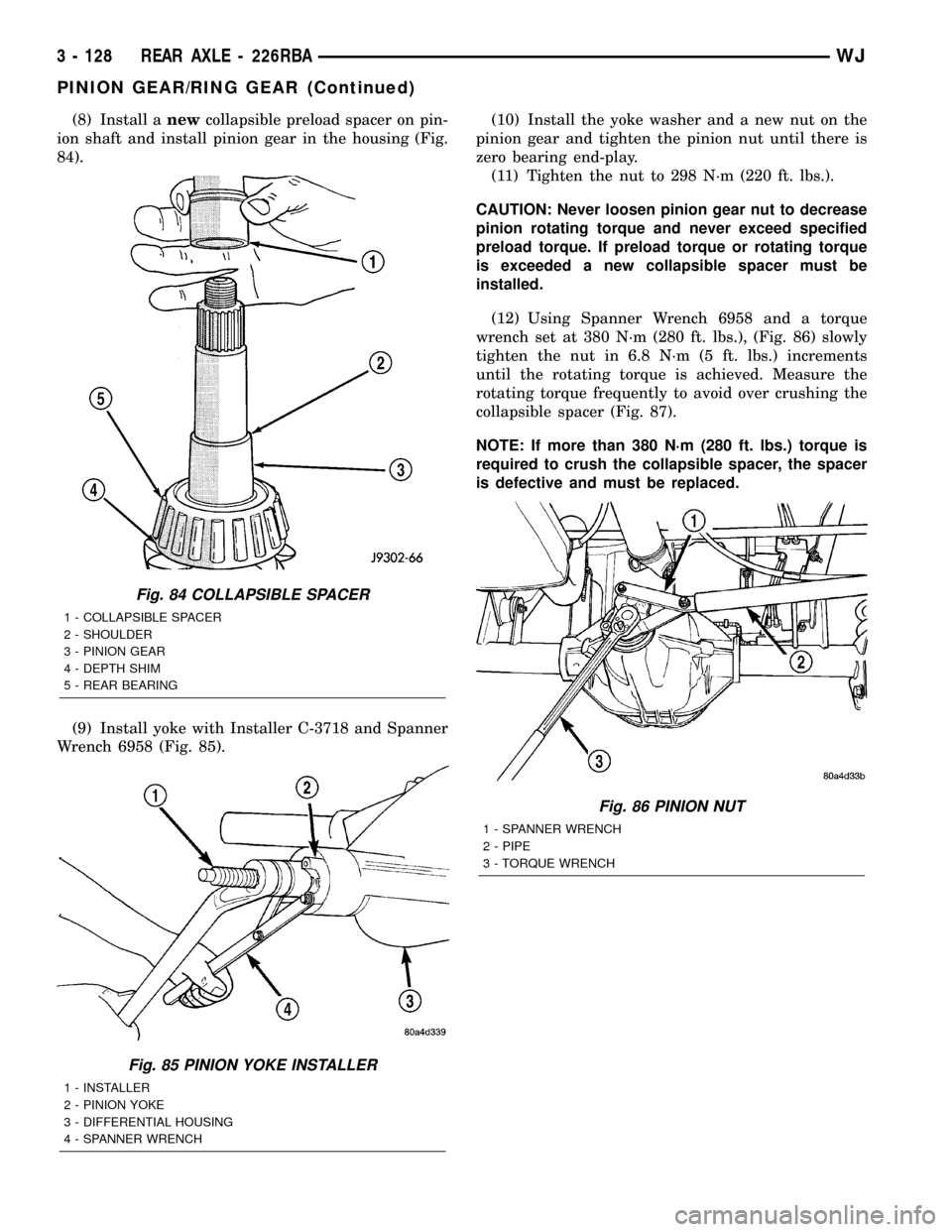
(8) Install anewcollapsible preload spacer on pin-
ion shaft and install pinion gear in the housing (Fig.
84).
(9) Install yoke with Installer C-3718 and Spanner
Wrench 6958 (Fig. 85).(10) Install the yoke washer and a new nut on the
pinion gear and tighten the pinion nut until there is
zero bearing end-play.
(11) Tighten the nut to 298 N´m (220 ft. lbs.).
CAUTION: Never loosen pinion gear nut to decrease
pinion rotating torque and never exceed specified
preload torque. If preload torque or rotating torque
is exceeded a new collapsible spacer must be
installed.
(12) Using Spanner Wrench 6958 and a torque
wrench set at 380 N´m (280 ft. lbs.), (Fig. 86) slowly
tighten the nut in 6.8 N´m (5 ft. lbs.) increments
until the rotating torque is achieved. Measure the
rotating torque frequently to avoid over crushing the
collapsible spacer (Fig. 87).
NOTE: If more than 380 N´m (280 ft. lbs.) torque is
required to crush the collapsible spacer, the spacer
is defective and must be replaced.
Fig. 84 COLLAPSIBLE SPACER
1 - COLLAPSIBLE SPACER
2 - SHOULDER
3 - PINION GEAR
4 - DEPTH SHIM
5 - REAR BEARING
Fig. 85 PINION YOKE INSTALLER
1 - INSTALLER
2 - PINION YOKE
3 - DIFFERENTIAL HOUSING
4 - SPANNER WRENCH
Fig. 86 PINION NUT
1 - SPANNER WRENCH
2 - PIPE
3 - TORQUE WRENCH
3 - 128 REAR AXLE - 226RBAWJ
PINION GEAR/RING GEAR (Continued)
Page 174 of 2199
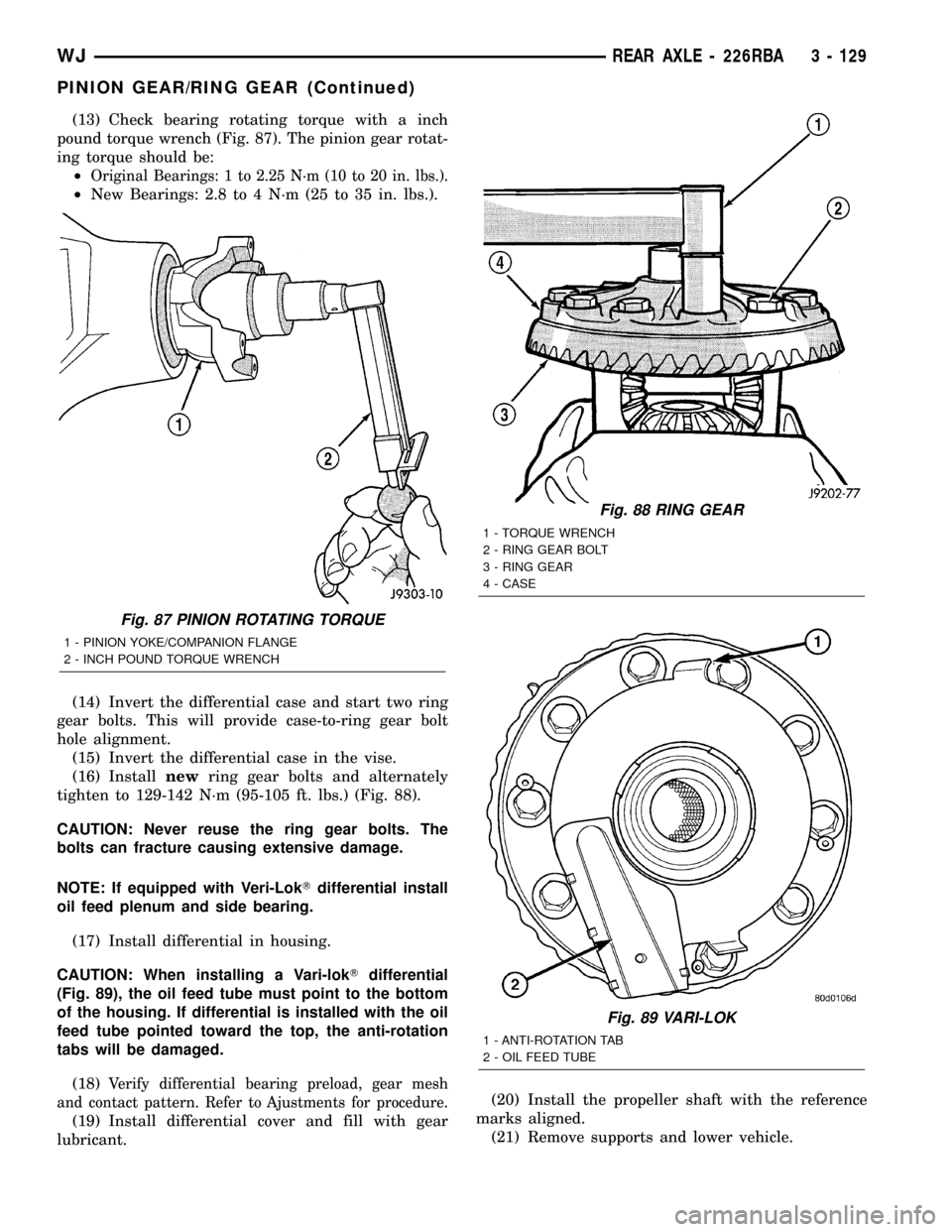
(13) Check bearing rotating torque with a inch
pound torque wrench (Fig. 87). The pinion gear rotat-
ing torque should be:
²
Original Bearings: 1 to 2.25 N´m (10 to 20 in. lbs.).
²New Bearings: 2.8 to 4 N´m (25 to 35 in. lbs.).
(14) Invert the differential case and start two ring
gear bolts. This will provide case-to-ring gear bolt
hole alignment.
(15) Invert the differential case in the vise.
(16) Installnewring gear bolts and alternately
tighten to 129-142 N´m (95-105 ft. lbs.) (Fig. 88).
CAUTION: Never reuse the ring gear bolts. The
bolts can fracture causing extensive damage.
NOTE: If equipped with Veri-LokTdifferential install
oil feed plenum and side bearing.
(17) Install differential in housing.
CAUTION: When installing a Vari-lokTdifferential
(Fig. 89), the oil feed tube must point to the bottom
of the housing. If differential is installed with the oil
feed tube pointed toward the top, the anti-rotation
tabs will be damaged.
(18)
Verify differential bearing preload, gear mesh
and contact pattern. Refer to Ajustments for procedure.
(19) Install differential cover and fill with gear
lubricant.(20) Install the propeller shaft with the reference
marks aligned.
(21) Remove supports and lower vehicle.
Fig. 87 PINION ROTATING TORQUE
1 - PINION YOKE/COMPANION FLANGE
2 - INCH POUND TORQUE WRENCH
Fig. 88 RING GEAR
1 - TORQUE WRENCH
2 - RING GEAR BOLT
3 - RING GEAR
4 - CASE
Fig. 89 VARI-LOK
1 - ANTI-ROTATION TAB
2 - OIL FEED TUBE
WJREAR AXLE - 226RBA 3 - 129
PINION GEAR/RING GEAR (Continued)
Page 194 of 2199
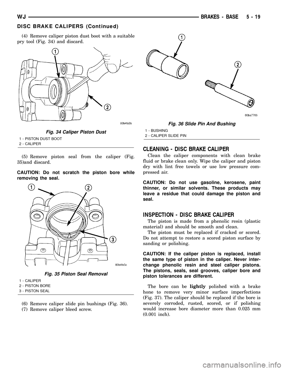
(4) Remove caliper piston dust boot with a suitable
pry tool (Fig. 34) and discard.
(5) Remove piston seal from the caliper (Fig.
35)and discard.
CAUTION: Do not scratch the piston bore while
removing the seal.
(6) Remove caliper slide pin bushings (Fig. 36).
(7) Remove caliper bleed screw.
CLEANING - DISC BRAKE CALIPER
Clean the caliper components with clean brake
fluid or brake clean only. Wipe the caliper and piston
dry with lint free towels or use low pressure com-
pressed air.
CAUTION: Do not use gasoline, kerosene, paint
thinner, or similar solvents. These products may
leave a residue that could damage the piston and
seal.
INSPECTION - DISC BRAKE CALIPER
The piston is made from a phenolic resin (plastic
material) and should be smooth and clean.
The piston must be replaced if cracked or scored.
Do not attempt to restore a scored piston surface by
sanding or polishing.
CAUTION: If the caliper piston is replaced, install
the same type of piston in the caliper. Never inter-
change phenolic resin and steel caliper pistons.
The pistons, seals, seal grooves, caliper bore and
piston tolerances are different.
The bore can belightlypolished with a brake
hone to remove very minor surface imperfections
(Fig. 37). The caliper should be replaced if the bore is
severely corroded, rusted, scored, or if polishing
would increase bore diameter more than 0.025 mm
(0.001 inch).
Fig. 34 Caliper Piston Dust
1 - PISTON DUST BOOT
2 - CALIPER
Fig. 35 Piston Seal Removal
1 - CALIPER
2 - PISTON BORE
3 - PISTON SEAL
Fig. 36 Slide Pin And Bushing
1 - BUSHING
2 - CALIPER SLIDE PIN
WJBRAKES - BASE 5 - 19
DISC BRAKE CALIPERS (Continued)
Page 204 of 2199
(5) Install the cluster bezel (Refer to 23 - BODY/
INSTRUMENT PANEL/CLUSTER BEZEL -
INSTALLATION).
(6) Reconnect the negative battery cable.
POWER BRAKE BOOSTER
DESCRIPTION
The booster assembly consists of a housing divided
into separate chambers by two internal diaphragms.
The outer edge of each diaphragm is attached to the
booster housing.
Two push rods are used in the booster. The pri-
mary push rod connects the booster to the brake
pedal. The secondary push rod connects the booster
to the master cylinder to stroke the cylinder pistons.
OPERATION
The atmospheric inlet valve is opened and closed
by the primary push rod. Booster vacuum supply is
through a hose attached to an intake manifold fittingat one end and to the booster check valve at the
other. The vacuum check valve in the booster housing
is a one-way device that prevents vacuum leak back.
Power assist is generated by utilizing the pressure
differential between normal atmospheric pressure
and a vacuum. The vacuum needed for booster oper-
ation is taken directly from the engine intake mani-
fold. The entry point for atmospheric pressure is
through a filter and inlet valve at the rear of the
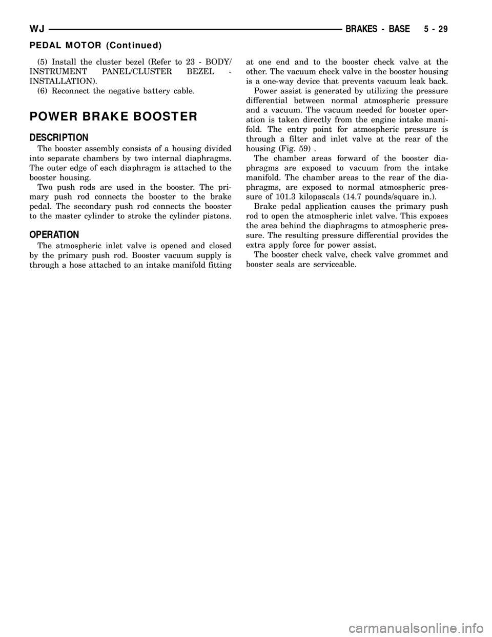
housing (Fig. 59) .
The chamber areas forward of the booster dia-
phragms are exposed to vacuum from the intake
manifold. The chamber areas to the rear of the dia-
phragms, are exposed to normal atmospheric pres-
sure of 101.3 kilopascals (14.7 pounds/square in.).
Brake pedal application causes the primary push
rod to open the atmospheric inlet valve. This exposes
the area behind the diaphragms to atmospheric pres-
sure. The resulting pressure differential provides the
extra apply force for power assist.
The booster check valve, check valve grommet and
booster seals are serviceable.
WJBRAKES - BASE 5 - 29
PEDAL MOTOR (Continued)
Page 207 of 2199
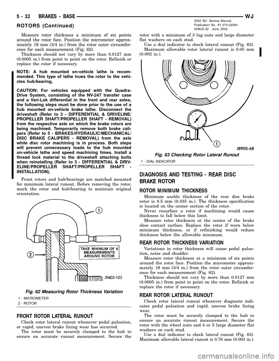
Measure rotor thickness a minimum of six points
around the rotor face. Position the micrometer approx-
imately 19 mm (3/4 in.) from the rotor outer circumfer-
ence for each measurement (Fig. 62).
Thickness should not vary by more than 0.0127 mm
(0.0005 in.) from point to point on the rotor. Refinish or
replace the rotor if necessary.
NOTE: A hub mounted on-vehicle lathe is recom-
mended. This type of lathe trues the rotor to the vehi-
cles hub/bearing.
CAUTION: For vehicles equipped with the Quadra-
Drive System, consisting of the NV-247 transfer case
and a Vari-Lok differential in the front and rear axles,
the following steps must be done prior to the use of a
hub mounted on-vehicle brake lathe. Disconnect the
driveshaft (Refer to 3 - DIFFERENTIAL & DRIVELINE/
PROPELLER SHAFT/PROPELLER SHAFT - REMOVAL)
from the respective axle on which the brake rotors are
being machined. Temporarily remove both brake cali-
pers (Refer to 5 - BRAKES/HYDRAULIC/MECHANICAL/
DISC BRAKE CALIPERS - REMOVAL) from the axle
while disc rotor machining is in process. Both steps
will prevent unnecessary loads to the hub mounted
on-vehicle lathe and speed machining times. Install a
thread lock material to the driveshaft attaching bolts
when reinstalling (Refer to 3 - DIFFERENTIAL & DRIV-
ELINE/PROPELLER SHAFT/PROPELLER SHAFT -
INSTALLATION).
Front rotors and hub/bearings are matched mounted
for minimum lateral runout. Before removing the rotor,
mark the rotor and hub/bearing to maintain original
orientation.
FRONT ROTOR LATERAL RUNOUT
Check rotor lateral runout whenever pedal pulsation,
or rapid, uneven brake lining wear has occurred.
The rotor must be securely clamped to the hub to
ensure an accurate runout measurement. Secure therotor with a minimum of 3 lug nuts and large diameter
flat washers on each stud.
Use a dial indicator to check lateral runout (Fig. 63).
Maximum allowable rotor lateral runout is 0.05 mm
(0.002 in.).
DIAGNOSIS AND TESTING - REAR DISC
BRAKE ROTOR
ROTOR MINIMUM THICKNESS
Minimum usable thickness of the rear disc brake
rotor is 8.5 mm (0.335 in.). The thickness specification
is located on the center section of the rotor.
Never resurface a rotor if machining would cause
thickness to fall below this limit.
Measure rotor thickness at the center of the brake
shoe contact surface. Replace the rotor if worn below
minimum thickness, or if refinishing would reduce
thickness below the allowable minimum.
REAR ROTOR THICKNESS VARIATION
Variations in rotor thickness will cause pedal pulsa-
tion, noise and shudder.
Measure rotor thickness at a minimum of six points
around the rotor face. Position the micrometer approxi-
mately 19 mm (3/4 in.) from the rotor outer circumfer-
ence for each measurement (Fig. 62).
Thickness should not vary by more than 0.0127 mm
(0.0005 in.) from point to point on the rotor. Refinish or
replace the rotor if necessary.
REAR ROTOR LATERAL RUNOUT
Check rotor lateral runout whenever diagnosis indi-
cates pedal pulsation and rapid, uneven brake lining
wear.
The rotor must be securely clamped to the hub to
ensure an accurate runout measurement. Secure the
rotor with the wheel nuts and 4 or 5 large diameter flat
washers on each stud.
Use a dial indicator to check lateral runout (Fig. 63).
Maximum allowable lateral runout is 0.76 mm (0.003 in.).
Fig. 62 Measuring Rotor Thickness Variation
1 - MICROMETER
2 - ROTOR
Fig. 63 Checking Rotor Lateral Runout
1 - DIAL INDICATOR
5 - 32 BRAKES - BASEWJ
ROTORS (Continued)
2002 WJ Service Manual
Publication No. 81-370-02064
02WJ5-32 June, 2002
Page 208 of 2199
STANDARD PROCEDURE - DISC ROTOR
MACHINING
CAUTION: For vehicles equipped with the Quadra-
Drive System, consisting of the NV-247 transfer case
and a Vari-Lok differential in the front and rear axles,
the following steps must be done prior to the use of a
hub mounted on-vehicle brake lathe. Disconnect the
driveshaft (Refer to 3 - DIFFERENTIAL & DRIVELINE/
PROPELLER SHAFT/PROPELLER SHAFT - REMOVAL)
from the respective axle on which the brake rotors are
being machined. Temporarily remove both brake cali-
pers (Refer to 5 - BRAKES/HYDRAULIC/MECHANICAL/
DISC BRAKE CALIPERS - REMOVAL) from the axle
while disc rotor machining is in process. Both steps
will prevent unnecessary loads to the hub mounted
on-vehicle lathe and speed machining times. Install a
thread lock material to the driveshaft attaching bolts
when reinstalling (Refer to 3 - DIFFERENTIAL & DRIV-
ELINE/PROPELLER SHAFT/PROPELLER SHAFT -
INSTALLATION).
NOTE: A hub mounted on-vehicle lathe is recom-
mended. This type of lathe trues the rotor to the vehi-
cles hub/bearing.
The disc brake rotor can be machined if scored or
worn. The lathe must machine both sides of the rotor
simultaneously with dual cutter heads. The rotor
mounting surface must be clean before placing on the
lathe. Equipment capable of machining only one side at
a time may produce a tapered rotor.
CAUTION: Brake rotors that do not meet minimum
thickness specifications before or after machining
must be replaced.
REMOVAL
REMOVAL - FRONT DISC BRAKE ROTOR
NOTE: Front rotors and hub/bearings are matched
mounted for minimum lateral runout. Before removing
the rotor, mark the rotor and hub/bearing to maintain
original orientation.
(1) Raise and support the vehicle.
(2) Remove wheel and tire assembly.
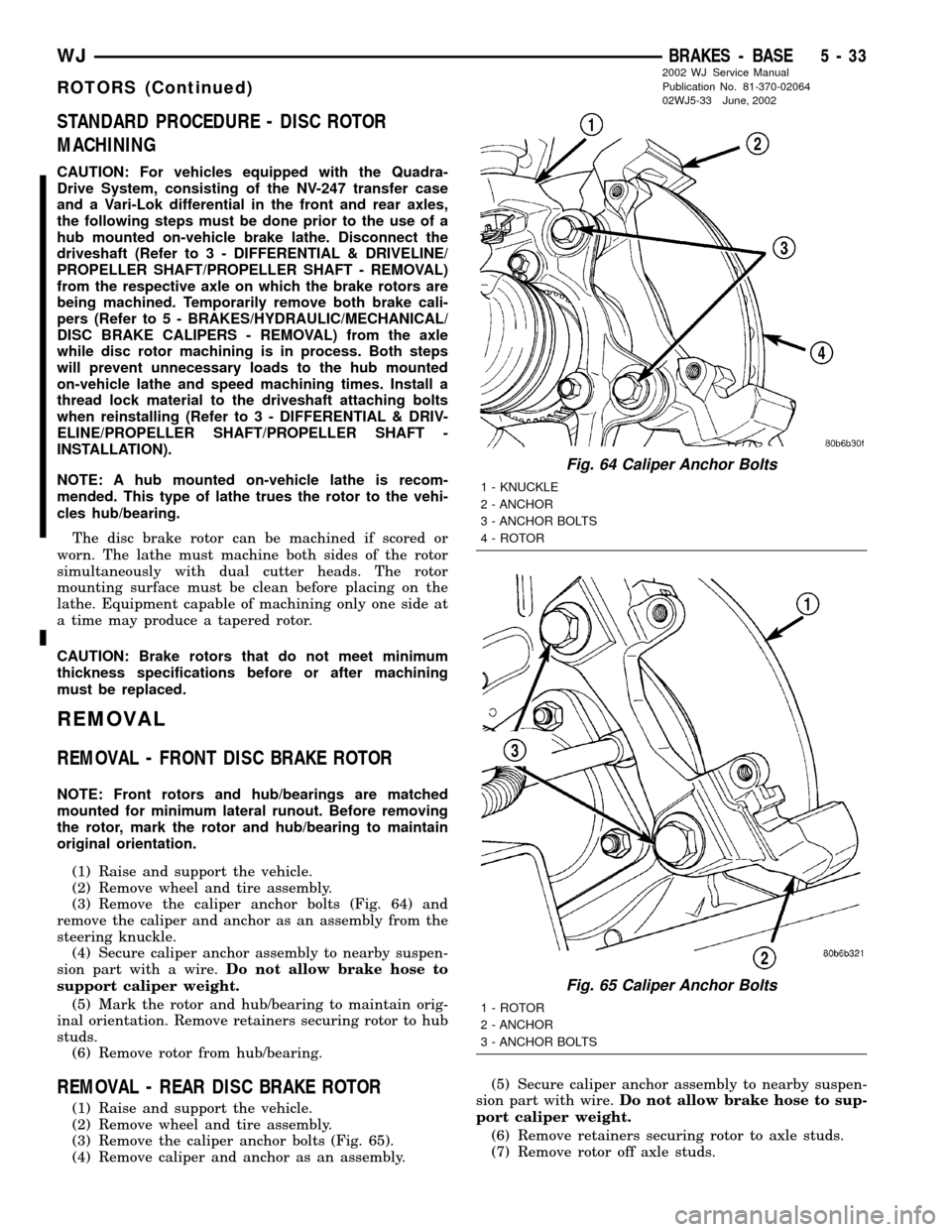
(3) Remove the caliper anchor bolts (Fig. 64) and
remove the caliper and anchor as an assembly from the
steering knuckle.
(4) Secure caliper anchor assembly to nearby suspen-
sion part with a wire.Do not allow brake hose to
support caliper weight.
(5) Mark the rotor and hub/bearing to maintain orig-
inal orientation. Remove retainers securing rotor to hub
studs.
(6) Remove rotor from hub/bearing.
REMOVAL - REAR DISC BRAKE ROTOR
(1) Raise and support the vehicle.
(2) Remove wheel and tire assembly.
(3) Remove the caliper anchor bolts (Fig. 65).
(4) Remove caliper and anchor as an assembly.(5) Secure caliper anchor assembly to nearby suspen-
sion part with wire.Do not allow brake hose to sup-
port caliper weight.
(6) Remove retainers securing rotor to axle studs.
(7) Remove rotor off axle studs.
Fig. 64 Caliper Anchor Bolts
1 - KNUCKLE
2 - ANCHOR
3 - ANCHOR BOLTS
4 - ROTOR
Fig. 65 Caliper Anchor Bolts
1 - ROTOR
2 - ANCHOR
3 - ANCHOR BOLTS
WJBRAKES - BASE 5 - 33
ROTORS (Continued)
2002 WJ Service Manual
Publication No. 81-370-02064
02WJ5-33 June, 2002
Page 242 of 2199
CONDITION POSSIBLE CAUSES CORRECTION
BELT BROKEN (NOTE: IDENTIFY
AND CORRECT PROBLEM
BEFORE NEW BELT IS
INSTALLED)1. Excessive tension. 1. Replace belt and automatic belt
tensioner.
2. Incorrect belt. 2. Replace belt.
3. Tensile member damaged during
belt installation.3. Replace belt.
4. Severe misalignment. 4. Check and replace.
5. Bracket, pulley, or bearing failure. 5. Replace defective component
and belt.
NOISE (OBJECTIONABLE
SQUEAL, SQUEAK, OR RUMBLE
IS HEARD OR FELT WHILE
DRIVE BELT IS IN OPERATION)1. Belt slippage. 1. Replace belt or automatic belt
tensioner.
2. Bearing noise. 2. Locate and repair.
3. Belt misalignment. 3. Replace belt.
4. Belt-to-pulley mismatch. 4. Install correct belt.
REMOVALÐ4.0L ENGINE
NOTE: The belt routing schematics are published
from the latest information available at the time of
publication. If anything differs between these sche-
matics and the Belt Routing Label, use the sche-
matics on Belt Routing Label. This label is located
in the engine compartment.
CAUTION: DO NOT LET TENSIONER ARM SNAP
BACK TO THE FREEARM POSITION, SEVERE DAM-
AGE MAY OCCUR TO THE TENSIONER.
Belt tension is not adjustable. Belt adjustment is
maintained by an automatic ( spring load ) belt ten-
sioner.
(1) Disconnect negative battery cable from battery.
(2) Rotate belt tensioner until it contacts its stop.
Remove belt, then slowly rotate the tensioner into
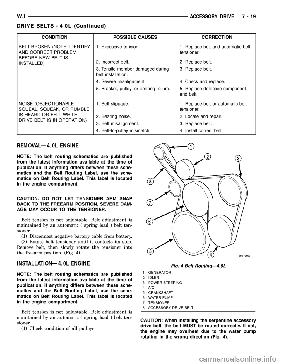
the freearm position. (Fig. 4).
INSTALLATIONÐ4.0L ENGINE
NOTE: The belt routing schematics are published
from the latest information available at the time of
publication. If anything differs between these sche-
matics and the Belt Routing Label, use the sche-
matics on Belt Routing Label. This label is located
in the engine compartment.
Belt tension is not adjustable. Belt adjustment is
maintained by an automatic ( spring load ) belt ten-
sioner.
(1) Check condition of all pulleys.CAUTION: When installing the serpentine accessory
drive belt, the belt MUST be routed correctly. If not,
the engine may overheat due to the water pump
rotating in the wrong direction (Fig. 4).
Fig. 4 Belt RoutingÐ4.0L
1 - GENERATOR
2 - IDLER
3 - POWER STEERING
4 - A/C
5 - CRANKSHAFT
6 - WATER PUMP
7 - TENSIONER
8 - ACCESSORY DRIVE BELT
WJACCESSORY DRIVE 7 - 19
DRIVE BELTS - 4.0L (Continued)
Page 245 of 2199
CONDITION POSSIBLE CAUSES CORRECTION
BELT BROKEN (NOTE: IDENTIFY
AND CORRECT PROBLEM
BEFORE NEW BELT IS
INSTALLED)1. Excessive tension. 1. Replace belt and automatic belt
tensioner.
2. Incorrect belt. 2. Replace belt.
3. Tensile member damaged during
belt installation.3. Replace belt.
4. Severe misalignment. 4. Check and replace.
5. Bracket, pulley, or bearing failure. 5. Replace defective component
and belt.
NOISE (OBJECTIONABLE
SQUEAL, SQUEAK, OR RUMBLE
IS HEARD OR FELT WHILE
DRIVE BELT IS IN OPERATION)1. Belt slippage. 1. Replace belt or automatic belt
tensioner.
2. Bearing noise. 2. Locate and repair.
3. Belt misalignment. 3. Replace belt.
4. Belt-to-pulley mismatch. 4. Install correct belt.
REMOVAL - 4.7L ENGINE
NOTE: The belt routing schematics are published
from the latest information available at the time of
publication. If anything differs between these sche-
matics and the Belt Routing Label, use the sche-
matics on Belt Routing Label. This label is located
in the engine compartment.
CAUTION: DO NOT LET TENSIONER ARM SNAP
BACK TO THE FREEARM POSITION, SEVERE DAM-
AGE MAY OCCUR TO THE TENSIONER.
Belt tension is not adjustable. Belt adjustment is
maintained by an automatic ( spring load ) belt ten-
sioner.
(1) Disconnect negative battery cable from battery.
(2) Rotate belt tensioner until it contacts its stop.
Remove belt, then slowly rotate the tensioner into
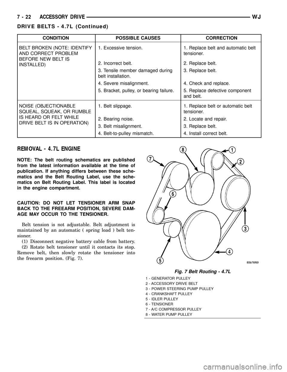
the freearm position. (Fig. 7).
Fig. 7 Belt Routing - 4.7L
1 - GENERATOR PULLEY
2 - ACCESSORY DRIVE BELT
3 - POWER STEERING PUMP PULLEY
4 - CRANKSHAFT PULLEY
5 - IDLER PULLEY
6 - TENSIONER
7 - A/C COMPRESSOR PULLEY
8 - WATER PUMP PULLEY
7 - 22 ACCESSORY DRIVEWJ
DRIVE BELTS - 4.7L (Continued)
Page 246 of 2199
INSTALLATION - 4.7L ENGINE
NOTE: The belt routing schematics are published
from the latest information available at the time of
publication. If anything differs between these sche-
matics and the Belt Routing Label, use the sche-
matics on Belt Routing Label. This label is located
in the engine compartment.
Belt tension is not adjustable. Belt adjustment is
maintained by an automatic ( spring load ) belt ten-
sioner.
(1) Check condition of all pulleys.
CAUTION: When installing the serpentine accessory
drive belt, the belt MUST be routed correctly. If not,
the engine may overheat due to the water pump
rotating in the wrong direction (Fig. 7).
(2) Install new belt (Fig. 7). Route the belt around
all pulleys except the idler pulley. Rotate the ten-
sioner arm until it contacts its stop position. Route
the belt around the idler and slowly let the tensioner
rotate into the belt. Make sure the belt is seated onto
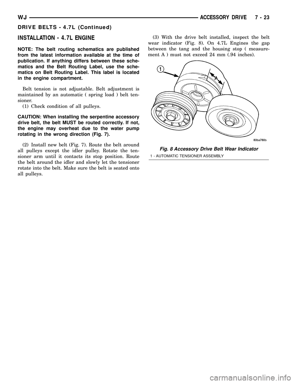
all pulleys.(3) With the drive belt installed, inspect the belt
wear indicator (Fig. 8). On 4.7L Engines the gap
between the tang and the housing stop ( measure-
ment A ) must not exceed 24 mm (.94 inches).
Fig. 8 Accessory Drive Belt Wear Indicator
1 - AUTOMATIC TENSIONER ASSEMBLY
WJACCESSORY DRIVE 7 - 23
DRIVE BELTS - 4.7L (Continued)
Page 248 of 2199
INSPECTION..........................52
INSTALLATION.........................52
RADIATOR PRESSURE CAP
DESCRIPTION.........................53
OPERATION...........................53
DIAGNOSIS AND TESTINGÐRADIATOR
PRESSURE CAP......................53CLEANING............................53
INSPECTION..........................54
WATER PUMP INLET TUBE
REMOVAL.............................54
INSTALLATION.........................54
COOLANT
DESCRIPTION
DESCRIPTION - ENGINE COOLANT
ETHYLENE-GLYCOL MIXTURES
CAUTION: Richer antifreeze mixtures cannot be
measured with normal field equipment and can
cause problems associated with 100 percent ethyl-
ene-glycol.
The required ethylene-glycol (antifreeze) and water
mixture depends upon the climate and vehicle oper-
ating conditions. The recommended mixture of 50/50
ethylene-glycol and water will provide protection
against freezing to -37 deg. C (-35 deg. F). The anti-
freeze concentrationmust alwaysbe a minimum of
44 percent, year-round in all climates.If percentage
is lower than 44 percent, engine parts may be
eroded by cavitation, and cooling system com-
ponents may be severely damaged by corrosion.
Maximum protection against freezing is provided
with a 68 percent antifreeze concentration, which
prevents freezing down to -67.7 deg. C (-90 deg. F). A
higher percentage will freeze at a warmer tempera-
ture. Also, a higher percentage of antifreeze can
cause the engine to overheat because the specific
heat of antifreeze is lower than that of water.
Use of 100 percent ethylene-glycol will cause for-
mation of additive deposits in the system, as the cor-
rosion inhibitive additives in ethylene-glycol require
the presence of water to dissolve. The deposits act as
insulation, causing temperatures to rise to as high as
149 deg. C (300) deg. F). This temperature is hot
enough to melt plastic and soften solder. The
increased temperature can result in engine detona-
tion. In addition, 100 percent ethylene-glycol freezes
at 22 deg. C (-8 deg. F ).
PROPYLENE-GLYCOL MIXTURES
It's overall effective temperature range is smaller
than that of ethylene-glycol. The freeze point of 50/50
propylene-glycol and water is -32 deg. C (-26 deg. F).
5 deg. C higher than ethylene-glycol's freeze point.
The boiling point (protection against summer boil-
over) of propylene-glycol is 125 deg. C (257 deg. F )at 96.5 kPa (14 psi), compared to 128 deg. C (263
deg. F) for ethylene-glycol. Use of propylene-glycol
can result in boil-over or freeze-up on a cooling sys-
tem designed for ethylene-glycol. Propylene glycol
also has poorer heat transfer characteristics than
ethylene glycol. This can increase cylinder head tem-
peratures under certain conditions.
Propylene-glycol/ethylene-glycol Mixtures can
cause the destabilization of various corrosion inhibi-
tors, causing damage to the various cooling system
components. Also, once ethylene-glycol and propy-
lene-glycol based coolants are mixed in the vehicle,
conventional methods of determining freeze point will
not be accurate. Both the refractive index and spe-
cific gravity differ between ethylene glycol and propy-
lene glycol.
DESCRIPTION - HOAT COOLANT
WARNING: ANTIFREEZE IS AN ETHYLENE GLYCOL
BASE COOLANT AND IS HARMFUL IF SWAL-
LOWED OR INHALED. IF SWALLOWED, DRINK
TWO GLASSES OF WATER AND INDUCE VOMIT-
ING. IF INHALED, MOVE TO FRESH AIR AREA.
SEEK MEDICAL ATTENTION IMMEDIATELY. DO NOT
STORE IN OPEN OR UNMARKED CONTAINERS.
WASH SKIN AND CLOTHING THOROUGHLY AFTER
COMING IN CONTACT WITH ETHYLENE GLYCOL.
KEEP OUT OF REACH OF CHILDREN. DISPOSE OF
GLYCOL BASE COOLANT PROPERLY, CONTACT
YOUR DEALER OR GOVERNMENT AGENCY FOR
LOCATION OF COLLECTION CENTER IN YOUR
AREA. DO NOT OPEN A COOLING SYSTEM WHEN
THE ENGINE IS AT OPERATING TEMPERATURE OR
HOT UNDER PRESSURE, PERSONAL INJURY CAN
RESULT. AVOID RADIATOR COOLING FAN WHEN
ENGINE COMPARTMENT RELATED SERVICE IS
PERFORMED, PERSONAL INJURY CAN RESULT.
CAUTION: Use of Propylene Glycol based coolants
is not recommended, as they provide less freeze
protection and less corrosion protection.
The cooling system is designed around the coolant.
The coolant must accept heat from engine metal, in
the cylinder head area near the exhaust valves and
engine block. Then coolant carries the heat to the
radiator where the tube/fin radiator can transfer the
heat to the air.
WJENGINE 7 - 25