driver seat JEEP GRAND CHEROKEE 2002 WJ / 2.G Owners Manual
[x] Cancel search | Manufacturer: JEEP, Model Year: 2002, Model line: GRAND CHEROKEE, Model: JEEP GRAND CHEROKEE 2002 WJ / 2.GPages: 2199, PDF Size: 76.01 MB
Page 1360 of 2199
CRANKSHAFT OIL SEAL -
REAR
REMOVAL
NOTE: This procedure can be performed in vehicle.
(1) If being preformed in vehicle, remove the
transmission.
(2) Remove the flexplate (Refer to 9 - ENGINE/
ENGINE BLOCK/FLEX PLATE - REMOVAL).
NOTE: The crankshaft oil seal CAN NOT be reused
after removal.
NOTE: The crankshaft rear oil seal remover Special
Tool 8506 must be installed deeply into the seal.
Continue to tighten the removal tool into the seal
until the tool can not be turned farther. Failure to
install tool correctly the first time will cause tool to
pull free of seal without removing seal from engine.
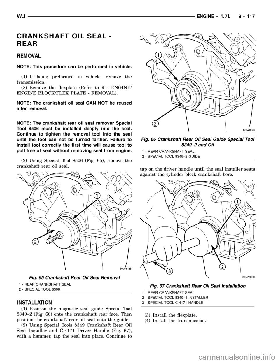
(3) Using Special Tool 8506 (Fig. 65), remove the
crankshaft rear oil seal.
INSTALLATION
(1) Position the magnetic seal guide Special Tool
8349±2 (Fig. 66) onto the crankshaft rear face. Then
position the crankshaft rear oil seal onto the guide.
(2) Using Special Tools 8349 Crankshaft Rear Oil
Seal Installer and C-4171 Driver Handle (Fig. 67),
with a hammer, tap the seal into place. Continue totap on the driver handle until the seal installer seats
against the cylinder block crankshaft bore.
(3) Install the flexplate.
(4) Install the transmission.
Fig. 65 Crankshaft Rear Oil Seal Removal
1 - REAR CRANKSHAFT SEAL
2 - SPECIAL TOOL 8506
Fig. 66 Crankshaft Rear Oil Seal Guide Special Tool
8349±2 and Oil
1 - REAR CRANKSHAFT SEAL
2 - SPECIAL TOOL 8349±2 GUIDE
Fig. 67 Crankshaft Rear Oil Seal Installation
1 - REAR CRANKSHAFT SEAL
2 - SPECIAL TOOL 8349±1 INSTALLER
3 - SPECIAL TOOL C-4171 HANDLE
WJENGINE - 4.7L 9 - 117
Page 1485 of 2199
REMOVAL
WARNING: BEFORE SERVICING THE STEERING
COLUMN THE AIRBAG SYSTEM MUST BE DIS-
ARMED. FAILURE TO DO SO MAY RESULT IN ACCI-
DENTAL DEPLOYMENT OF THE AIRBAG AND
POSSIBLE PERSONAL INJURY.(Refer to 8 - ELEC-
TRICAL/RESTRAINTS/DRIVER AIRBAG - REMOVAL).
(1) Position front wheels straight ahead.
(2) Disconnect and isolate the negative (ground)
cable from the battery.
(3) Remove the airbag,(Refer to 8 - ELECTRICAL/
RESTRAINTS/DRIVER AIRBAG - REMOVAL).
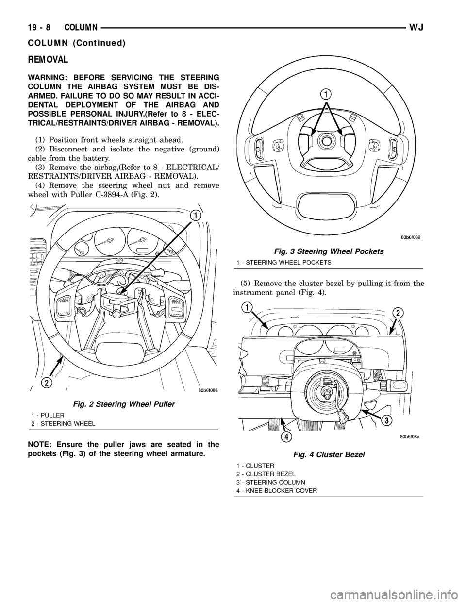
(4) Remove the steering wheel nut and remove
wheel with Puller C-3894-A (Fig. 2).
NOTE: Ensure the puller jaws are seated in the
pockets (Fig. 3) of the steering wheel armature.(5) Remove the cluster bezel by pulling it from the
instrument panel (Fig. 4).
Fig. 2 Steering Wheel Puller
1 - PULLER
2 - STEERING WHEEL
Fig. 3 Steering Wheel Pockets
1 - STEERING WHEEL POCKETS
Fig. 4 Cluster Bezel
1 - CLUSTER
2 - CLUSTER BEZEL
3 - STEERING COLUMN
4 - KNEE BLOCKER COVER
19 - 8 COLUMNWJ
COLUMN (Continued)
Page 1490 of 2199
necessary, the steering column assembly must be
replaced,(Refer to 19 - STEERING/COLUMN -
REMOVAL).
REMOVAL
IGNITION SWITCH REMOVAL
The ignition key must be in the key cylinder for
cylinder removal. The key cylinder must be removed
first before removing ignition switch.
(1) Remove key cylinder. Refer to previous steps.
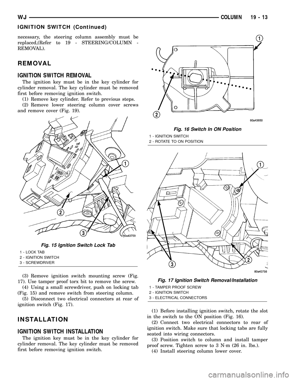
(2) Remove lower steering column cover screws
and remove cover (Fig. 19).
(3) Remove ignition switch mounting screw (Fig.
17). Use tamper proof torx bit to remove the screw.
(4) Using a small screwdriver, push on locking tab
(Fig. 15) and remove switch from steering column.
(5) Disconnect two electrical connectors at rear of
ignition switch (Fig. 17).
INSTALLATION
IGNITION SWITCH INSTALLATION
The ignition key must be in the key cylinder for
cylinder removal. The key cylinder must be removed
first before removing ignition switch.(1) Before installing ignition switch, rotate the slot
in the switch to the ON position (Fig. 16).
(2) Connect two electrical connectors to rear of
ignition switch. Make sure that locking tabs are fully
seated into wiring connectors.
(3) Position switch to column and install tamper
proof screw. Tighten screw to 3 N´m (26 in. lbs.).
(4) Install steering column lower cover.
Fig. 15 Ignition Switch Lock Tab
1 - LOCK TAB
2 - IGNITION SWITCH
3 - SCREWDRIVER
Fig. 16 Switch In ON Position
1 - IGNITION SWITCH
2 - ROTATE TO ON POSITION
Fig. 17 Ignition Switch Removal/Installation
1 - TAMPER PROOF SCREW
2 - IGNITION SWITCH
3 - ELECTRICAL CONNECTORS
WJCOLUMN 19 - 13
IGNITION SWITCH (Continued)
Page 1498 of 2199
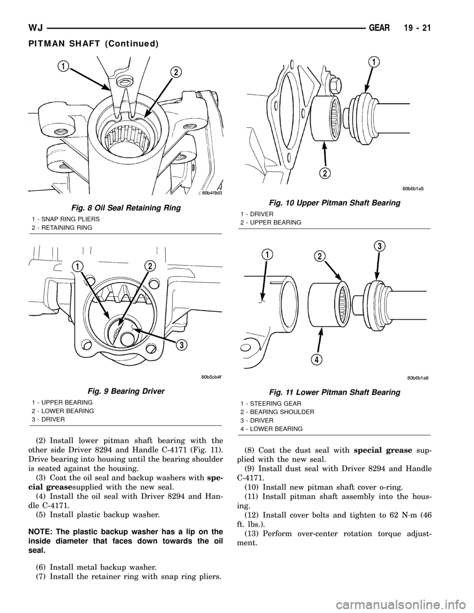
(2) Install lower pitman shaft bearing with the
other side Driver 8294 and Handle C-4171 (Fig. 11).
Drive bearing into housing until the bearing shoulder
is seated against the housing.
(3) Coat the oil seal and backup washers withspe-
cial greasesupplied with the new seal.
(4) Install the oil seal with Driver 8294 and Han-
dle C-4171.
(5) Install plastic backup washer.
NOTE: The plastic backup washer has a lip on the
inside diameter that faces down towards the oil
seal.
(6) Install metal backup washer.
(7) Install the retainer ring with snap ring pliers.(8) Coat the dust seal withspecial greasesup-
plied with the new seal.
(9) Install dust seal with Driver 8294 and Handle
C-4171.
(10) Install new pitman shaft cover o-ring.
(11) Install pitman shaft assembly into the hous-
ing.
(12) Install cover bolts and tighten to 62 N´m (46
ft. lbs.).
(13) Perform over-center rotation torque adjust-
ment.
Fig. 8 Oil Seal Retaining Ring
1 - SNAP RING PLIERS
2 - RETAINING RING
Fig. 9 Bearing Driver
1 - UPPER BEARING
2 - LOWER BEARING
3 - DRIVER
Fig. 10 Upper Pitman Shaft Bearing
1 - DRIVER
2 - UPPER BEARING
Fig. 11 Lower Pitman Shaft Bearing
1 - STEERING GEAR
2 - BEARING SHOULDER
3 - DRIVER
4 - LOWER BEARING
WJGEAR 19 - 21
PITMAN SHAFT (Continued)
Page 1499 of 2199

PITMAN SHAFT BEARING
REMOVAL
(1) Clean exposed end of pitman shaft and housing
with a wire brush.
(2) Rotate the stub shaft with a wrench (Fig.
5)from stop to stop and count the number of turns.
(3) Center the stub shaft by rotating it from the
stop 1/2 of the total amount of turns.
NOTE: The pitman shaft will not clear the housing if
it is not centered.
(4) Remove pitman shaft cover bolts and remove
the shaft assembly (Fig. 6).
(5) Remove pitman shaft cover o-ring.
(6) Remove pitman shaft dust seal from the hous-
ing with a Puller 7794-A and Slide Hammer C-637
(Fig. 7).
(7) Remove the pitman shaft oil seal retaining ring
with snap ring pliers (Fig. 8).
(8) Remove oil seal metal backup washer then
plastic backup washer from the housing (Fig. 12).
(9)
Remove pitman shaft oil seal from the housing
with a Puller 7794-A and Slide Hammer C-637 (Fig. 7).
(10) Drop Driver 8277 through the top bearing and
align the driver up with the lower bearing. (Fig. 9).
Install Handle C-4171 into the driver and remove the
lower bearing.
(11) Turn the gear over and remover the upper
bearing with Driver 8277 and Handle C-4171.
INSTALLATION
(1) Install upper pitman shaft bearing, with Driver
8294 and Handle C-4171 (Fig. 10). Drive bearing into
housing until the driver bottoms out.NOTE: Install upper pitman shaft bearing with the
part number/letters facing the driver.
(2) Install lower pitman shaft bearing with the
other side Driver 8294 and Handle C-4171 (Fig. 11).
Drive bearing into housing until the bearing shoulder
is seated against the housing.
(3) Coat the oil seal and backup washers withspe-
cial greasesupplied with the new seal.
(4) Install the oil seal with Driver 8294 and Han-
dle C-4171.
(5) Install plastic backup washer.
NOTE: The plastic backup washer has a lip on the
inside diameter that faces down towards the oil
seal.
(6) Install metal backup washer.
(7) Install the retainer ring with snap ring pliers.
(8) Coat the dust seal withspecial greasesup-
plied with the new seal.
(9) Install dust seal with Driver 8294 and Handle
C-4171.
(10) Install new pitman shaft cover o-ring.
(11) Install pitman shaft assembly into the hous-
ing.
(12) Install cover bolts and tighten to 62 N´m (46
ft. lbs.).
(13) Perform over-center rotation torque adjust-
ment.
PITMAN SHAFT SEAL
REMOVAL
(1) Clean exposed end of pitman shaft and housing
with a wire brush.
(2) Rotate the stub shaft with a wrench (Fig.
5)from stop to stop and count the number of turns.
(3) Center the stub shaft by rotating it from the
stop 1/2 of the total amount of turns.
NOTE: The pitman shaft will not clear the housing if
it is not centered.
(4) Remove pitman shaft cover bolts and remove
the shaft assembly (Fig. 6).
(5) Remove pitman shaft cover o-ring.
(6) Remove pitman shaft dust seal from the hous-
ing with a Puller 7794-A and Slide Hammer C-637
(Fig. 7).
(7) Remove the pitman shaft oil seal retaining ring
with snap ring pliers (Fig. 8).
(8) Remove oil seal metal backup washer then
plastic backup washer from the housing (Fig. 12).
Fig. 12 Backup Washers
1 - METAL BACK UP WASHER
2 - PLASTIC BACK UP WASHER
19 - 22 GEARWJ
Page 1500 of 2199
(9) Remove pitman shaft oil seal from the housing
with a Puller 7794-A and Slide Hammer C-637 (Fig.
7).
(10) Drop Driver 8277 through the top bearing and
align the driver up with the lower bearing. (Fig. 9).
Install Handle C-4171 into the driver and remove the
lower bearing.
(11) Turn the gear over and remover the upper
bearing with Driver 8277 and Handle C-4171.
INSTALLATION
(1) Install upper pitman shaft bearing, with Driver
8294 and Handle C-4171 (Fig. 10). Drive bearing into
housing until the driver bottoms out.
NOTE: Install upper pitman shaft bearing with the
part number/letters facing the driver.
(2) Install lower pitman shaft bearing with the
other side Driver 8294 and Handle C-4171 (Fig. 11).
Drive bearing into housing until the bearing shoulder
is seated against the housing.
(3) Coat the oil seal and backup washers withspe-
cial greasesupplied with the new seal.
(4) Install the oil seal with Driver 8294 and Han-
dle C-4171.
(5) Install plastic backup washer.
NOTE: The plastic backup washer has a lip on the
inside diameter that faces down towards the oil
seal.
(6) Install metal backup washer.
(7) Install the retainer ring with snap ring pliers.
(8) Coat the dust seal withspecial greasesup-
plied with the new seal.
(9) Install dust seal with Driver 8294 and Handle
C-4171.
(10) Install new pitman shaft cover o-ring.
(11) Install pitman shaft assembly into the hous-
ing.
(12) Install cover bolts and tighten to 62 N´m (46
ft. lbs.).
(13) Perform over-center rotation torque adjust-
ment.
RACK PISTON/VALVE
ASSEMBLY
REMOVAL
(1) Remove the steering gear (Refer to 19 -
STEERING/GEAR - REMOVAL).
(2) Clean exposed end of pitman shaft and housing
with a wire brush.
(3) Rotate the stub shaft with a wrench (Fig.
5)from stop to stop and count the number of turns.(4) Center the stub shaft by rotating it from the
stop 1/2 of the total amount of turns.
NOTE: The pitman shaft will not clear the housing if
it is not centered.
(5) Remove pitman shaft cover bolts and remove
the shaft assembly (Fig. 6).
(6) Remove the pitman shaft cover o-ring.
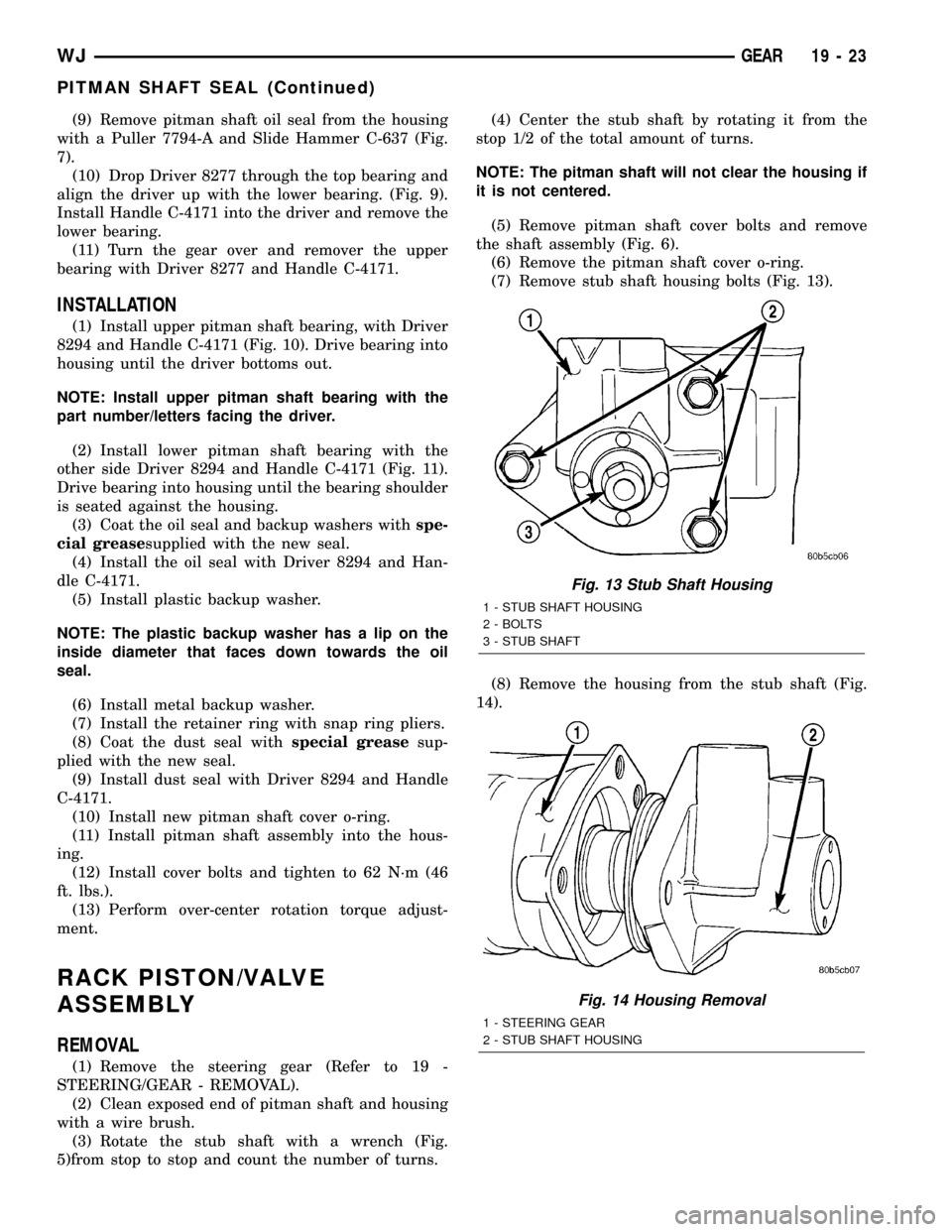
(7) Remove stub shaft housing bolts (Fig. 13).
(8) Remove the housing from the stub shaft (Fig.
14).
Fig. 13 Stub Shaft Housing
1 - STUB SHAFT HOUSING
2 - BOLTS
3 - STUB SHAFT
Fig. 14 Housing Removal
1 - STEERING GEAR
2 - STUB SHAFT HOUSING
WJGEAR 19 - 23
PITMAN SHAFT SEAL (Continued)
Page 1532 of 2199

The rear servo and governor pressure ports are at
the right rear of the transmission case. The overdrive
clutch pressure port is at the left rear of the case.
Test One - Transmission In Manual Low
NOTE: This test checks pump output, pressure reg-
ulation, and condition of the rear clutch and servo
circuit. Both test gauges are required for this test.
(1) Connect tachometer to engine. Position tachom-
eter so it can be observed from driver seat if helper
will be operating engine. Raise vehicle on hoist that
will allow rear wheels to rotate freely.
(2) Connect 100 psi Gauge C-3292 to accumulator
port. Then connect 300 psi Gauge C-3293-SP to rear
servo port.
(3) Disconnect throttle and gearshift cables from
levers on transmission valve body manual shaft.
(4) Have helper start and run engine at 1000 rpm.
(5) Move transmission shift lever fully forward
into 1 range.(6) Gradually move transmission throttle lever
from full forward to full rearward position and note
pressures on both gauges:
²Line pressure at accumulator port should be
54-60 psi (372-414 kPa) with throttle lever forward
and gradually increase to 90-96 psi (621-662 kPa) as
throttle lever is moved rearward.
²Rear servo pressure should be same as line pres-
sure within 3 psi (20.68 kPa).
Test Two - Transmission In 2 Range
NOTE: This test checks pump output, line pressure
and pressure regulation. Use 100 psi Test Gauge
C-3292 for this test.
(1) Leave vehicle in place on hoist and leave Test
Gauge C-3292 connected to accumulator port.
(2) Have helper start and run engine at 1000 rpm.
(3) Move transmission shift lever one detent rear-
ward from full forward position. This is 2 range.
(4) Move transmission throttle lever from full for-
ward to full rearward position and read pressure on
gauge.
(5) Line pressure should be 54-60 psi (372-414
kPa) with throttle lever forward and gradually
increase to 90-96 psi (621-662 kPa) as lever is moved
rearward.
Test Three - Transmission In D Range Third Gear
NOTE: This test checks pressure regulation and
condition of the clutch circuits. Both test gauges
are required for this test.
(1) Turn OD switch off.
(2) Leave vehicle on hoist and leave Gauge C-3292
in place at accumulator port.
(3) Move Gauge C-3293-SP over to front servo port
for this test.
(4) Have helper start and run engine at 1600 rpm
for this test.
(5) Move transmission shift lever two detents rear-
ward from full forward position. This is D range.
(6) Read pressures on both gauges as transmission
throttle lever is gradually moved from full forward to
full rearward position:
²Line pressure at accumulator in D range third
gear, should be 54-60 psi (372-414 kPa) with throttle
lever forward and increase as lever is moved rear-
ward.
²Front servo pressure in D range third gear,
should be within 3 psi (21 kPa) of line pressure up to
kickdown point.
Fig. 9 Pressure Test Port Locations
1 - OVERDRIVE CLUTCH TEST PORT
2 - GOVERNOR TEST PORT
3 - ACCUMULATOR TEST PORT
4 - FRONT SERVO TEST PORT
5 - REAR SERVO TEST PORT
WJAUTOMATIC TRANSMISSION - 42RE 21 - 13
AUTOMATIC TRANSMISSION - 42RE (Continued)
Page 1533 of 2199
Test Four - Transmission In Reverse
NOTE: This test checks pump output, pressure reg-
ulation and the front clutch and rear servo circuits.
Use 300 psi Test Gauge C-3293-SP for this test.
(1) Leave vehicle on hoist and leave gauge C-3292
in place at accumulator port.
(2) Move 300 psi Gauge C-3293-SP back to rear
servo port.
(3) Have helper start and run engine at 1600 rpm
for test.
(4) Move transmission shift lever four detents
rearward from full forward position. This is Reverse
range.
(5) Move transmission throttle lever fully forward
then fully rearward and note reading at Gauge
C-3293-SP.
(6) Pressure should be 145 - 175 psi (1000-1207
kPa) with throttle lever forward and increase to 230 -
280 psi (1586-1931 kPa) as lever is gradually moved
rearward.
Test Five - Governor Pressure
NOTE: This test checks governor operation by mea-
suring governor pressure response to changes in
vehicle speed. It is usually not necessary to check
governor operation unless shift speeds are incor-
rect or if the transmission will not downshift. The
test should be performed on the road or on a hoist
that will allow the rear wheels to rotate freely.
(1) Move 100 psi Test Gauge C-3292 to governor
pressure port.
(2) Move transmission shift lever two detents rear-
ward from full forward position. This is D range.
(3) Have helper start and run engine at curb idle
speed. Then firmly apply service brakes so wheels
will not rotate.
(4) Note governor pressure:
²Governor pressure should be no more than 20.6
kPa (3 psi) at curb idle speed and wheels not rotat-
ing.
²If pressure exceeds 20.6 kPa (3 psi), a fault
exists in governor pressure control system.
(5) Release brakes, slowly increase engine speed,
and observe speedometer and pressure test gauge (do
not exceed 30 mph on speedometer). Governor pres-
sure should increase in proportion to vehicle speed.
Or approximately 6.89 kPa (1 psi) for every 1 mph.
(6) Governor pressure rise should be smooth and
drop back to no more than 20.6 kPa (3 psi), after
engine returns to curb idle and brakes are applied to
prevent wheels from rotating.
(7) Compare results of pressure test with analysis
chart.Test Six - Transmission In Overdrive Fourth Gear
NOTE: This test checks line pressure at the over-
drive clutch in fourth gear range. Use 300 psi Test
Gauge C-3293-SP for this test. The test should be
performed on the road or on a chassis dyno.
(1) Remove tachometer; it is not needed for this
test.
(2) Move 300 psi Gauge to overdrive clutch pres-
sure test port. Then remove other gauge and reinstall
test port plug.
(3) Lower vehicle.
(4) Turn OD switch on.
(5) Secure test gauge so it can be viewed from
drivers seat.
(6) Start engine and shift into D range.
(7) Increase vehicle speed gradually until 3-4 shift
occurs and note gauge pressure.
(8) Pressure should be 469-496 kPa (68-72 psi)
with closed throttle and increase to 620-827 kPa (90-
120 psi) at 1/2 to 3/4 throttle. Note that pressure can
increase to around 896 kPa (130 psi) at full throttle.
(9) Return to shop or move vehicle off chassis
dyno.
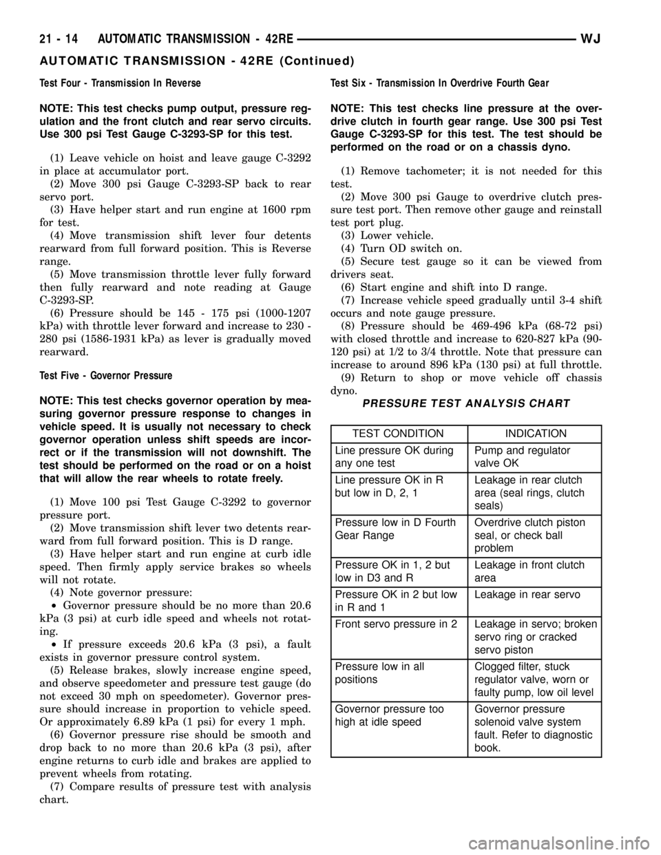
PRESSURE TEST ANALYSIS CHART
TEST CONDITION INDICATION
Line pressure OK during
any one testPump and regulator
valve OK
Line pressure OK in R
but low in D, 2, 1Leakage in rear clutch
area (seal rings, clutch
seals)
Pressure low in D Fourth
Gear RangeOverdrive clutch piston
seal, or check ball
problem
Pressure OK in 1, 2 but
low in D3 and RLeakage in front clutch
area
Pressure OK in 2 but low
in R and 1Leakage in rear servo
Front servo pressure in 2 Leakage in servo; broken
servo ring or cracked
servo piston
Pressure low in all
positionsClogged filter, stuck
regulator valve, worn or
faulty pump, low oil level
Governor pressure too
high at idle speedGovernor pressure
solenoid valve system
fault. Refer to diagnostic
book.
21 - 14 AUTOMATIC TRANSMISSION - 42REWJ
AUTOMATIC TRANSMISSION - 42RE (Continued)
Page 1557 of 2199
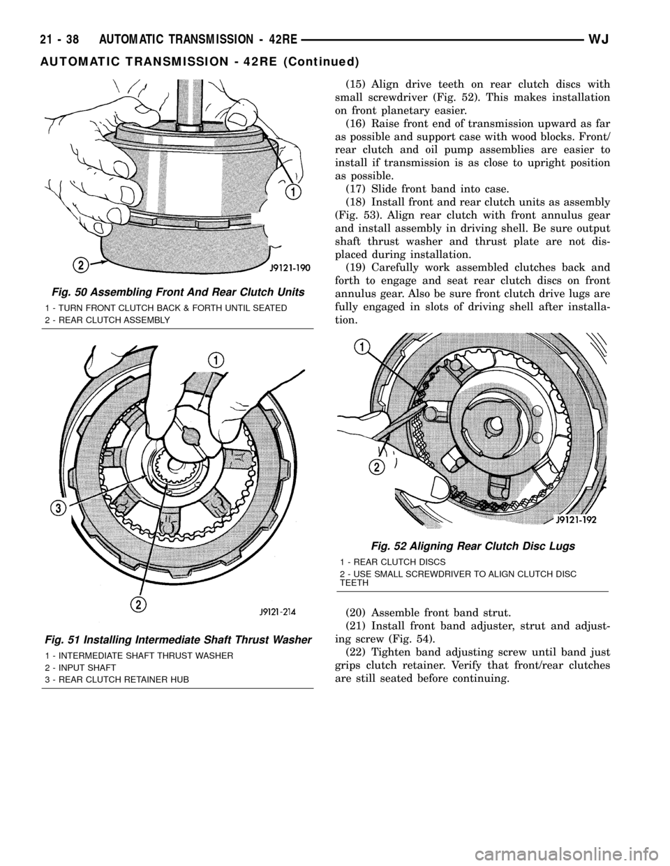
(15) Align drive teeth on rear clutch discs with
small screwdriver (Fig. 52). This makes installation
on front planetary easier.
(16) Raise front end of transmission upward as far
as possible and support case with wood blocks. Front/
rear clutch and oil pump assemblies are easier to
install if transmission is as close to upright position
as possible.
(17) Slide front band into case.
(18) Install front and rear clutch units as assembly
(Fig. 53). Align rear clutch with front annulus gear
and install assembly in driving shell. Be sure output
shaft thrust washer and thrust plate are not dis-
placed during installation.
(19) Carefully work assembled clutches back and
forth to engage and seat rear clutch discs on front
annulus gear. Also be sure front clutch drive lugs are
fully engaged in slots of driving shell after installa-
tion.
(20) Assemble front band strut.
(21) Install front band adjuster, strut and adjust-
ing screw (Fig. 54).
(22) Tighten band adjusting screw until band just
grips clutch retainer. Verify that front/rear clutches
are still seated before continuing.
Fig. 50 Assembling Front And Rear Clutch Units
1 - TURN FRONT CLUTCH BACK & FORTH UNTIL SEATED
2 - REAR CLUTCH ASSEMBLY
Fig. 51 Installing Intermediate Shaft Thrust Washer
1 - INTERMEDIATE SHAFT THRUST WASHER
2 - INPUT SHAFT
3 - REAR CLUTCH RETAINER HUB
Fig. 52 Aligning Rear Clutch Disc Lugs
1 - REAR CLUTCH DISCS
2 - USE SMALL SCREWDRIVER TO ALIGN CLUTCH DISC
TEETH
21 - 38 AUTOMATIC TRANSMISSION - 42REWJ
AUTOMATIC TRANSMISSION - 42RE (Continued)
Page 1604 of 2199
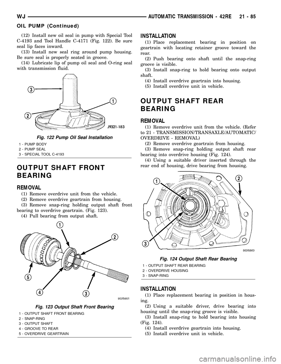
(12) Install new oil seal in pump with Special Tool
C-4193 and Tool Handle C-4171 (Fig. 122). Be sure
seal lip faces inward.
(13) Install new seal ring around pump housing.
Be sure seal is properly seated in groove.
(14) Lubricate lip of pump oil seal and O-ring seal
with transmission fluid.
OUTPUT SHAFT FRONT
BEARING
REMOVAL
(1) Remove overdrive unit from the vehicle.
(2) Remove overdrive geartrain from housing.
(3) Remove snap-ring holding output shaft front
bearing to overdrive geartrain. (Fig. 123).
(4) Pull bearing from output shaft.
INSTALLATION
(1) Place replacement bearing in position on
geartrain with locating retainer groove toward the
rear.
(2) Push bearing onto shaft until the snap-ring
groove is visible.
(3) Install snap-ring to hold bearing onto output
shaft.
(4) Install overdrive geartrain into housing.
(5) Install overdrive unit in vehicle.
OUTPUT SHAFT REAR
BEARING
REMOVAL
(1) Remove overdrive unit from the vehicle. (Refer
to 21 - TRANSMISSION/TRANSAXLE/AUTOMATIC/
OVERDRIVE - REMOVAL)
(2) Remove overdrive geartrain from housing.
(3) Remove snap-ring holding output shaft rear
bearing into overdrive housing (Fig. 124).
(4) Using a suitable driver inserted through the
rear end of housing, drive bearing from housing.
INSTALLATION
(1) Place replacement bearing in position in hous-
ing.
(2) Using a suitable driver, drive bearing into
housing until the snap-ring groove is visible.
(3) Install snap-ring to hold bearing into housing
(Fig. 124).
(4) Install overdrive geartrain into housing.
(5) Install overdrive unit in vehicle.
Fig. 122 Pump Oil Seal Installation
1 - PUMP BODY
2 - PUMP SEAL
3 - SPECIAL TOOL C-4193
Fig. 123 Output Shaft Front Bearing
1 - OUTPUT SHAFT FRONT BEARING
2 - SNAP-RING
3 - OUTPUT SHAFT
4 - GROOVE TO REAR
5 - OVERDRIVE GEARTRAIN
Fig. 124 Output Shaft Rear Bearing
1 - OUTPUT SHAFT REAR BEARING
2 - OVERDRIVE HOUSING
3 - SNAP-RING
WJAUTOMATIC TRANSMISSION - 42RE 21 - 85
OIL PUMP (Continued)