tow JEEP GRAND CHEROKEE 2002 WJ / 2.G Workshop Manual
[x] Cancel search | Manufacturer: JEEP, Model Year: 2002, Model line: GRAND CHEROKEE, Model: JEEP GRAND CHEROKEE 2002 WJ / 2.GPages: 2199, PDF Size: 76.01 MB
Page 1264 of 2199
CLEANING
Thoroughly clean the engine cylinder head and cyl-
inder block mating surfaces. Clean the intake and
engine exhaust manifold and engine cylinder head
mating surfaces. Remove all gasket material and car-
bon.
Check to ensure that no coolant or foreign material
has fallen into the tappet bore area.
Remove the carbon deposits from the combustion
chambers and top of the pistons.
INSPECTION
Use a straightedge and feeler gauge to check the
flatness of the engine cylinder head and block mating
surfaces.
INSTALLATION
NOTE: This procedure can be done with the engine
in or out of the vehicle.
The engine cylinder head gasket is a composition
gasket. The gasket is to be installed DRY.DO NOT
use a gasket sealing compound on the gasket.
If the engine cylinder head is to be replaced and
the original valves used, measure the valve stem
diameter. Only standard size valves can be used with
a service replacement engine cylinder head unless
the replacement head valve stem guide bores are
reamed to accommodate oversize valve stems.
Remove all carbon buildup and reface the valves.
(1) Remove the shop towels from the cylinder
bores. Coat the bores with clean engine oil.
(2) Position the engine cylinder head gasket (with
the numbers facing up) using the alignment dowels
in the cylinder block, to position the gasket.
CAUTION: Engine cylinder head bolts should be
reused only once. Replace the head bolts if they
were used before or if they have a paint dab on the
top of the bolt.
(3) With bolt No.14 held in place (tape around
bolt), install the engine cylinder head over the same
dowels used to locate the gasket. Remove the tape
from bolt No.14.
(4) Coat the threads of stud bolt No.11 with Loc-
tite 592 sealant, or equivalent.
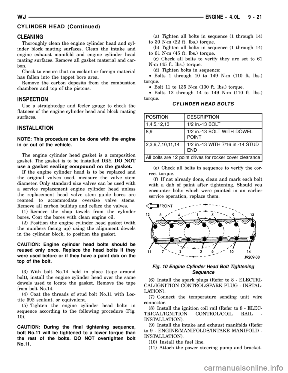
(5) Tighten the engine cylinder head bolts in
sequence according to the following procedure (Fig.
10).
CAUTION: During the final tightening sequence,
bolt No.11 will be tightened to a lower torque than
the rest of the bolts. DO NOT overtighten bolt
No.11.(a) Tighten all bolts in sequence (1 through 14)
to 30 N´m (22 ft. lbs.) torque.
(b) Tighten all bolts in sequence (1 through 14)
to 61 N´m (45 ft. lbs.) torque.
(c) Check all bolts to verify they are set to 61
N´m (45 ft. lbs.) torque.
(d) Tighten bolts in sequence:
²Bolts 1 through 10 to 149 N´m (110 ft. lbs.)
torque.
²Bolt 11 to 135 N´m (100 ft. lbs.) torque.
²Bolts 12 through 14 to 149 N´m (110 ft. lbs.)
torque.
CYLINDER HEAD BOLTS
POSITION DESCRIPTION
1,4,5,12,13 1/2 in.-13 BOLT
8,9 1/2 in.-13 BOLT WITH DOWEL
POINT
2,3,6,7,10,11,14 1/2 in.-13 WITH 7/16 in.-14 STUD
END
All bolts are 12 point drives for rocker cover clearance
(e) Check all bolts in sequence to verify the cor-
rect torque.
(f) If not already done, clean and mark each bolt
with a dab of paint after tightening. Should you
encounter bolts which were painted in an earlier
service operation, replace them.
(6) Install the spark plugs (Refer to 8 - ELECTRI-
CAL/IGNITION CONTROL/SPARK PLUG - INSTAL-
LATION).
(7) Connect the temperature sending unit wire
connector.
(8) Install the ignition coil rail (Refer to 8 - ELEC-
TRICAL/IGNITION CONTROL/COIL RAIL -
INSTALLATION).
(9) Install the intake and exhaust manifolds (Refer
to 9 - ENGINE/MANIFOLDS/INTAKE MANIFOLD -
INSTALLATION).
(10) Install the fuel line.
(11) Attach the power steering pump and bracket.
Fig. 10 Engine Cylinder Head Bolt Tightening
Sequence
WJENGINE - 4.0L 9 - 21
CYLINDER HEAD (Continued)
Page 1279 of 2199
CRANKSHAFT MAIN
BEARINGS
STANDARD PROCEDURE - FITTING
CRANKSHAFT MAIN BEARINGS
FITTING BEARINGS (CRANKSHAFT INSTALLED)
The main bearing caps, numbered (front to rear)
from 1 through 7 have an arrow to indicate the for-
ward position. The upper main bearing inserts are
grooved to provide oil channels while the lower
inserts are smooth.
Each bearing insert pair is selectively fitted to its
respective journal to obtain the specified operating
clearance. In production, the select fit is obtained by
using various-sized color-coded bearing insert pairs
as listed in the Main Bearing Fitting Chart. The
bearing color code appears on the edge of the insert.
The size is not stamped on bearing inserts used
for engine production.
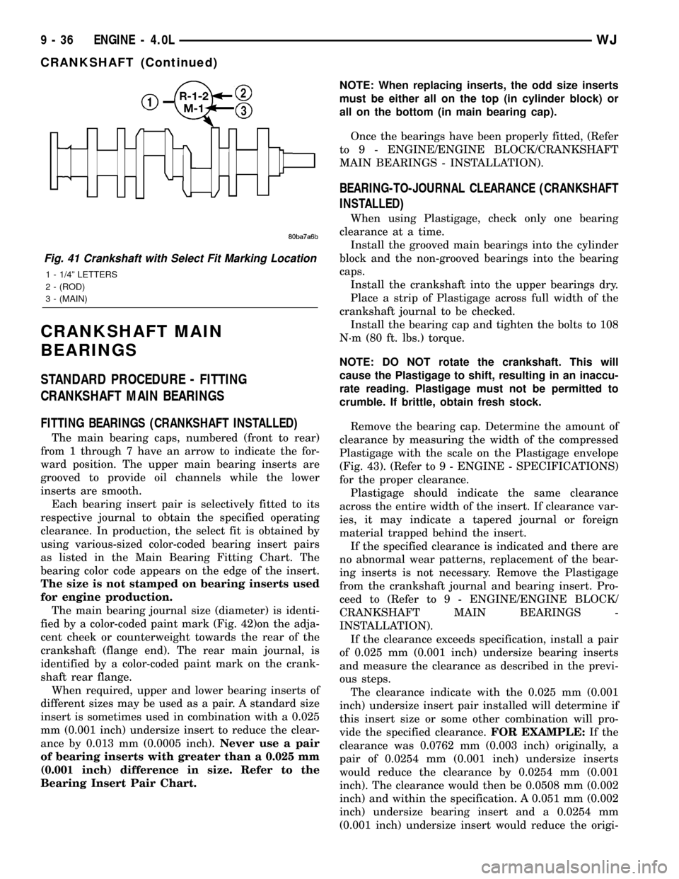
The main bearing journal size (diameter) is identi-
fied by a color-coded paint mark (Fig. 42)on the adja-
cent cheek or counterweight towards the rear of the
crankshaft (flange end). The rear main journal, is
identified by a color-coded paint mark on the crank-
shaft rear flange.
When required, upper and lower bearing inserts of
different sizes may be used as a pair. A standard size
insert is sometimes used in combination with a 0.025
mm (0.001 inch) undersize insert to reduce the clear-
ance by 0.013 mm (0.0005 inch).Never use a pair
of bearing inserts with greater than a 0.025 mm
(0.001 inch) difference in size. Refer to the
Bearing Insert Pair Chart.NOTE: When replacing inserts, the odd size inserts
must be either all on the top (in cylinder block) or
all on the bottom (in main bearing cap).
Once the bearings have been properly fitted, (Refer
to 9 - ENGINE/ENGINE BLOCK/CRANKSHAFT
MAIN BEARINGS - INSTALLATION).
BEARING-TO-JOURNAL CLEARANCE (CRANKSHAFT
INSTALLED)
When using Plastigage, check only one bearing
clearance at a time.
Install the grooved main bearings into the cylinder
block and the non-grooved bearings into the bearing
caps.
Install the crankshaft into the upper bearings dry.
Place a strip of Plastigage across full width of the
crankshaft journal to be checked.
Install the bearing cap and tighten the bolts to 108
N´m (80 ft. lbs.) torque.
NOTE: DO NOT rotate the crankshaft. This will
cause the Plastigage to shift, resulting in an inaccu-
rate reading. Plastigage must not be permitted to
crumble. If brittle, obtain fresh stock.
Remove the bearing cap. Determine the amount of
clearance by measuring the width of the compressed
Plastigage with the scale on the Plastigage envelope
(Fig. 43). (Refer to 9 - ENGINE - SPECIFICATIONS)
for the proper clearance.
Plastigage should indicate the same clearance
across the entire width of the insert. If clearance var-
ies, it may indicate a tapered journal or foreign
material trapped behind the insert.
If the specified clearance is indicated and there are
no abnormal wear patterns, replacement of the bear-
ing inserts is not necessary. Remove the Plastigage
from the crankshaft journal and bearing insert. Pro-
ceed to (Refer to 9 - ENGINE/ENGINE BLOCK/
CRANKSHAFT MAIN BEARINGS -
INSTALLATION).
If the clearance exceeds specification, install a pair
of 0.025 mm (0.001 inch) undersize bearing inserts
and measure the clearance as described in the previ-
ous steps.
The clearance indicate with the 0.025 mm (0.001
inch) undersize insert pair installed will determine if
this insert size or some other combination will pro-
vide the specified clearance.FOR EXAMPLE:If the
clearance was 0.0762 mm (0.003 inch) originally, a
pair of 0.0254 mm (0.001 inch) undersize inserts
would reduce the clearance by 0.0254 mm (0.001
inch). The clearance would then be 0.0508 mm (0.002
inch) and within the specification. A 0.051 mm (0.002
inch) undersize bearing insert and a 0.0254 mm
(0.001 inch) undersize insert would reduce the origi-
Fig. 41 Crankshaft with Select Fit Marking Location
1 - 1/4º LETTERS
2 - (ROD)
3 - (MAIN)
9 - 36 ENGINE - 4.0LWJ
CRANKSHAFT (Continued)
Page 1285 of 2199
CRANKSHAFT OIL SEAL -
REAR
REMOVAL
The crankshaft rear main bearing oil seal consists
of two half pieces of viton with a single lip that effec-
tively seals the rear of the crankshaft. Replace the
upper and lower seal halves as a unit to ensure leak-
free operation.
(1) Remove transmission inspection cover.
(2) Remove oil pan. (Refer to 9 - ENGINE/LUBRI-
CATION/OIL PAN - REMOVAL)
(3) Remove main bearing cap brace.
(4) Remove rear main bearing cap (No.7).
(5) Push upper seal out of the groove. Ensure that
the crankshaft and seal groove are not damaged.
(6) Remove lower half of the seal from the bearing
cap.
INSTALLATION
The crankshaft rear main bearing oil seal consists
of two half pieces of viton with a single lip that effec-
tively seals the rear of the crankshaft. Replace the
upper and lower seal halves as a unit to ensure leak-
free operation.
(1) Wipe the seal surface area of the crankshaft
until it is clean.
(2) Apply a thin coat of engine oil.
(3) Coat lip of the seal with engine oil.
(4) Carefully position the upper seal into the
groove in the cylinder block. The lip of the seal faces
toward the front of the engine.
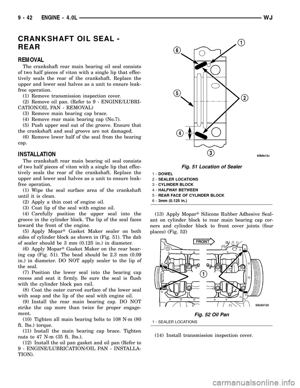
(5) Apply MopartGasket Maker sealer on both
sides of cylinder block as shown in (Fig. 51). The dab
of sealer should be 3 mm (0.125 in.) in diameter.
(6) Apply MopartGasket Maker on the rear bear-
ing cap (Fig. 51). The bead should be 2.3 mm (0.09
in.) in diameter. DO NOT apply sealer to the lip of
the seal.
(7) Position the lower seal into the bearing cap
recess and seat it firmly. Be sure the seal is flush
with the cylinder block pan rail.
(8) Coat the outer curved surface of the lower seal
with soap and the lip of the seal with engine oil.
(9) Install the rear main bearing cap. DO NOT
strike the cap more than twice for proper engage-
ment.
(10) Tighten all main bearing bolts to 108 N´m (80
ft. lbs.) torque.
(11) Install the main bearing cap brace. Tighten
nuts to 47 N´m (35 ft. lbs.).
(12) Install the oil pan gasket and oil pan (Refer to
9 - ENGINE/LUBRICATION/OIL PAN - INSTALLA-
TION).(13) Apply MopartSilicone Rubber Adhesive Seal-
ant on cylinder block to rear main bearing cap cor-
ners and cylinder block to front cover joints (four
places) (Fig. 52)
(14) Install transmission inspection cover.
Fig. 51 Location of Sealer
1-DOWEL
2-SEALER LOCATIONS
3-CYLINDER BLOCK
4-HALFWAY BETWEEN
5-REAR FACE OF CYLINDER BLOCK
6-3mm (0.125 in.)
Fig. 52 Oil Pan
1 - SEALER LOCATIONS
9 - 42 ENGINE - 4.0LWJ
Page 1289 of 2199
(11) Lower the vehicle until it is about 2 feet from
the floor.
CAUTION: Ensure that the connecting rod bolts DO
NOT scratch the crankshaft journals or cylinder
walls. Short pieces of rubber hose, slipped over the
rod bolts will provide protection during removal.
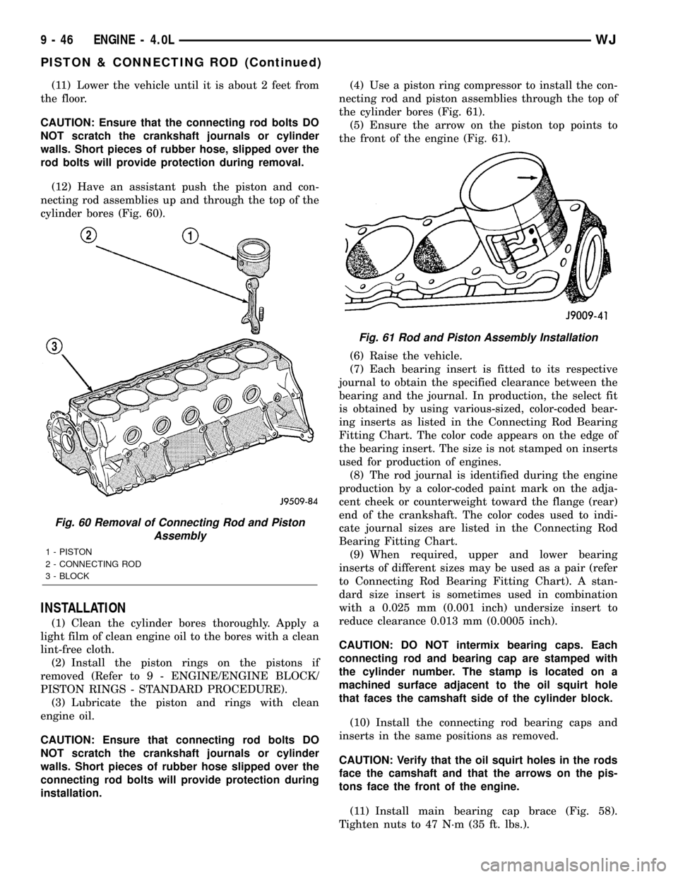
(12) Have an assistant push the piston and con-
necting rod assemblies up and through the top of the
cylinder bores (Fig. 60).
INSTALLATION
(1) Clean the cylinder bores thoroughly. Apply a
light film of clean engine oil to the bores with a clean
lint-free cloth.
(2) Install the piston rings on the pistons if
removed (Refer to 9 - ENGINE/ENGINE BLOCK/
PISTON RINGS - STANDARD PROCEDURE).
(3) Lubricate the piston and rings with clean
engine oil.
CAUTION: Ensure that connecting rod bolts DO
NOT scratch the crankshaft journals or cylinder
walls. Short pieces of rubber hose slipped over the
connecting rod bolts will provide protection during
installation.(4) Use a piston ring compressor to install the con-
necting rod and piston assemblies through the top of
the cylinder bores (Fig. 61).
(5) Ensure the arrow on the piston top points to
the front of the engine (Fig. 61).
(6) Raise the vehicle.
(7) Each bearing insert is fitted to its respective
journal to obtain the specified clearance between the
bearing and the journal. In production, the select fit
is obtained by using various-sized, color-coded bear-
ing inserts as listed in the Connecting Rod Bearing
Fitting Chart. The color code appears on the edge of
the bearing insert. The size is not stamped on inserts
used for production of engines.
(8) The rod journal is identified during the engine
production by a color-coded paint mark on the adja-
cent cheek or counterweight toward the flange (rear)
end of the crankshaft. The color codes used to indi-
cate journal sizes are listed in the Connecting Rod
Bearing Fitting Chart.
(9) When required, upper and lower bearing
inserts of different sizes may be used as a pair (refer
to Connecting Rod Bearing Fitting Chart). A stan-
dard size insert is sometimes used in combination
with a 0.025 mm (0.001 inch) undersize insert to
reduce clearance 0.013 mm (0.0005 inch).
CAUTION: DO NOT intermix bearing caps. Each
connecting rod and bearing cap are stamped with
the cylinder number. The stamp is located on a
machined surface adjacent to the oil squirt hole
that faces the camshaft side of the cylinder block.
(10) Install the connecting rod bearing caps and
inserts in the same positions as removed.
CAUTION: Verify that the oil squirt holes in the rods
face the camshaft and that the arrows on the pis-
tons face the front of the engine.
(11) Install main bearing cap brace (Fig. 58).
Tighten nuts to 47 N´m (35 ft. lbs.).
Fig. 60 Removal of Connecting Rod and Piston
Assembly
1 - PISTON
2 - CONNECTING ROD
3 - BLOCK
Fig. 61 Rod and Piston Assembly Installation
9 - 46 ENGINE - 4.0LWJ
PISTON & CONNECTING ROD (Continued)
Page 1302 of 2199
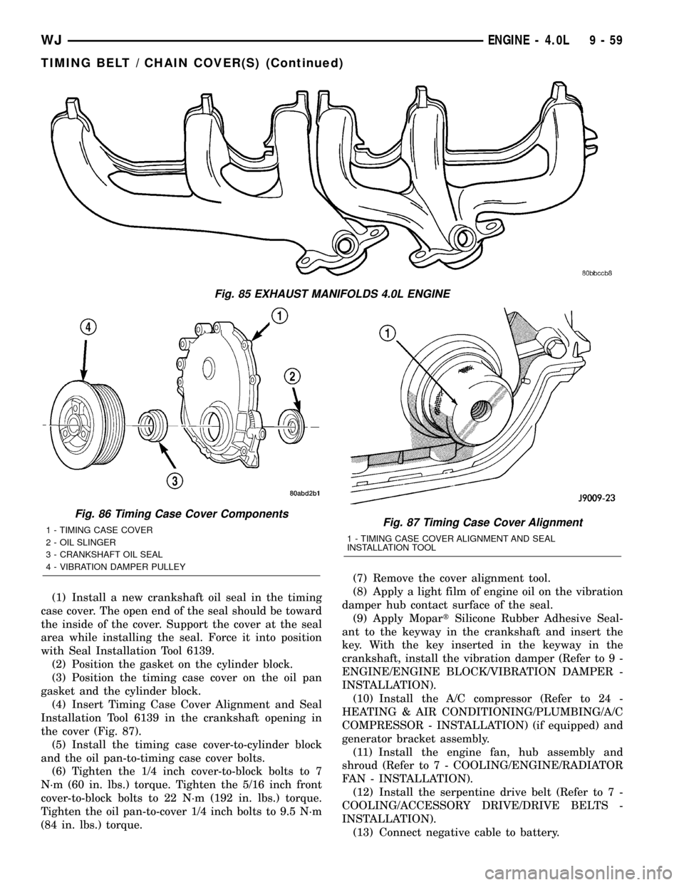
(1) Install a new crankshaft oil seal in the timing
case cover. The open end of the seal should be toward
the inside of the cover. Support the cover at the seal
area while installing the seal. Force it into position
with Seal Installation Tool 6139.
(2) Position the gasket on the cylinder block.
(3) Position the timing case cover on the oil pan
gasket and the cylinder block.
(4) Insert Timing Case Cover Alignment and Seal
Installation Tool 6139 in the crankshaft opening in
the cover (Fig. 87).
(5) Install the timing case cover-to-cylinder block
and the oil pan-to-timing case cover bolts.
(6) Tighten the 1/4 inch cover-to-block bolts to 7
N´m (60 in. lbs.) torque. Tighten the 5/16 inch front
cover-to-block bolts to 22 N´m (192 in. lbs.) torque.
Tighten the oil pan-to-cover 1/4 inch bolts to 9.5 N´m
(84 in. lbs.) torque.(7) Remove the cover alignment tool.
(8) Apply a light film of engine oil on the vibration
damper hub contact surface of the seal.
(9) Apply MopartSilicone Rubber Adhesive Seal-
ant to the keyway in the crankshaft and insert the
key. With the key inserted in the keyway in the
crankshaft, install the vibration damper (Refer to 9 -
ENGINE/ENGINE BLOCK/VIBRATION DAMPER -
INSTALLATION).
(10) Install the A/C compressor (Refer to 24 -
HEATING & AIR CONDITIONING/PLUMBING/A/C
COMPRESSOR - INSTALLATION) (if equipped) and
generator bracket assembly.
(11) Install the engine fan, hub assembly and
shroud (Refer to 7 - COOLING/ENGINE/RADIATOR
FAN - INSTALLATION).
(12) Install the serpentine drive belt (Refer to 7 -
COOLING/ACCESSORY DRIVE/DRIVE BELTS -
INSTALLATION).
(13) Connect negative cable to battery.
Fig. 85 EXHAUST MANIFOLDS 4.0L ENGINE
Fig. 86 Timing Case Cover Components
1 - TIMING CASE COVER
2 - OIL SLINGER
3 - CRANKSHAFT OIL SEAL
4 - VIBRATION DAMPER PULLEYFig. 87 Timing Case Cover Alignment
1 - TIMING CASE COVER ALIGNMENT AND SEAL
INSTALLATION TOOL
WJENGINE - 4.0L 9 - 59
TIMING BELT / CHAIN COVER(S) (Continued)
Page 1313 of 2199
STANDARD PROCEDURE
STANDARD PROCEDURE - REPAIR DAMAGED
OR WORN THREADS
CAUTION: Be sure that the tapped holes maintain
the original center line.
Damaged or worn threads can be repaired. Essen-
tially, this repair consists of:
²Drilling out worn or damaged threads.
²Tapping the hole with a special Heli-Coil Tap, or
equivalent.
²Installing an insert into the tapped hole to bring
the hole back to its original thread size.
STANDARD PROCEDURE - FORM-IN-PLACE
GASKETS AND SEALERS
There are numerous places where form-in-place
gaskets are used on the engine. Care must be taken
when applying form-in-place gaskets to assure
obtaining the desired results.Do not use form-in-
place gasket material unless specified.Bead size,
continuity, and location are of great importance. Too
thin a bead can result in leakage while too much can
result in spill-over which can break off and obstruct
fluid feed lines. A continuous bead of the proper
width is essential to obtain a leak-free gasket.
There are numerous types of form-in-place gasket
materials that are used in the engine area. Mopart
Engine RTV GEN II, MopartATF-RTV, and Mopart
Gasket Maker gasket materials, each have different
properties and can not be used in place of the other.
MOPARtENGINE RTV GEN II
MopartEngine RTV GEN II is used to seal com-
ponents exposed to engine oil. This material is a spe-
cially designed black silicone rubber RTV that
retains adhesion and sealing properties when
exposed to engine oil. Moisture in the air causes the
material to cure. This material is available in three
ounce tubes and has a shelf life of one year. After one
year this material will not properly cure. Always
inspect the package for the expiration date before
use.
MOPARtATF RTV
MopartATF RTV is a specifically designed black
silicone rubber RTV that retains adhesion and seal-
ing properties to seal components exposed to auto-
matic transmission fluid, engine coolants, and
moisture. This material is available in three ounce
tubes and has a shelf life of one year. After one year
this material will not properly cure. Always inspect
the package for the expiration date before use.
MOPARtGASKET MAKER
MopartGasket Maker is an anaerobic type gasket
material. The material cures in the absence of airwhen squeezed between two metallic surfaces. It will
not cure if left in the uncovered tube. The anaerobic
material is for use between two machined surfaces.
Do not use on flexible metal flanges.
MOPARtGASKET SEALANT
MopartGasket Sealant is a slow drying, perma-
nently soft sealer. This material is recommended for
sealing threaded fittings and gaskets against leakage
of oil and coolant. Can be used on threaded and
machined parts under all temperatures. This mate-
rial is used on engines with multi-layer steel (MLS)
cylinder head gaskets. This material also will pre-
vent corrosion. MopartGasket Sealant is available in
a 13 oz. aerosol can or 4oz./16 oz. can w/applicator.
FORM-IN-PLACE GASKET AND SEALER
APPLICATION
Assembling parts using a form-in-place gasket
requires care but it's easier then using precut gas-
kets.
MopartGasket Maker material should be applied
sparingly 1 mm (0.040 in.) diameter or less of sealant
to one gasket surface. Be certain the material sur-
rounds each mounting hole. Excess material can eas-
ily be wiped off. Components should be torqued in
place within 15 minutes. The use of a locating dowel
is recommended during assembly to prevent smear-
ing material off the location.
MopartEngine RTV GEN II or ATF RTV gasket
material should be applied in a continuous bead
approximately 3 mm (0.120 in.) in diameter. All
mounting holes must be circled. For corner sealing, a
3.17 or 6.35 mm (1/8 or 1/4 in.) drop is placed in the
center of the gasket contact area. Uncured sealant
may be removed with a shop towel. Components
should be torqued in place while the sealant is still
wet to the touch (within 10 minutes). The usage of a
locating dowel is recommended during assembly to
prevent smearing material off the location.
MopartGasket Sealant in an aerosol can should be
applied using a thin, even coat sprayed completely
over both surfaces to be joined, and both sides of a
gasket. Then proceed with assembly. Material in a
can w/applicator can be brushed on evenly over the
sealing surfaces. Material in an aerosol can should be
used on engines with multi-layer steel gaskets.
STANDARD PROCEDURE - ENGINE GASKET
SURFACE PREPARATION
To ensure engine gasket sealing, proper surface
preparation must be performed, especially with the
use of aluminum engine components and multi-layer
steel cylinder head gaskets.
Neveruse the following to clean gasket surfaces:
²Metal scraper
9 - 70 ENGINE - 4.7LWJ
ENGINE - 4.7L (Continued)
Page 1351 of 2199
(4) For rocker arm installation on cylinders 1 and
7 Rotate the crankshaft until cylinder #2 is at TDC
compression stroke.
(5) Using special tool 8516 press downward on the
valve spring, install rocker arm (Fig. 44).
(6) Install the cylinder head cover (Refer to 9 -
ENGINE/CYLINDER HEAD/CYLINDER HEAD
COVER(S) - INSTALLATION).
VALVE SPRINGS
DESCRIPTION
The valve springs are made from high strength
chrome silicon steel. The springs are common for
intake and exhaust applications. The valve spring
seat is integral with the valve stem seal, which is a
positive type seal to control lubrication.
VALVE STEM SEALS
DESCRIPTION
The valve stem seals are made of rubber and incor-
porate an integral steel valve spring seat. The inte-
gral garter spring maintains consistent lubrication
control to the valve stems.
ENGINE BLOCK
DESCRIPTION
The cylinder block is made of cast iron. The block
is a closed deck design with the left bank forward. To
provide high rigidity and improved NVH an
enhanced compacted graphite bedplate is bolted to
the block. The block design allows coolant flow
between the cylinders bores, and an internal coolant
bypass to a single poppet inlet thermostat is included
in the cast aluminum front cover.
STANDARD PROCEDUREÐCYLINDER BORE
HONING
Before honing, stuff plenty of clean shop towels
under the bores and over the crankshaft to keep
abrasive materials from entering the crankshaft
area.
(1) Used carefully, the Cylinder Bore Sizing Hone
C-823, equipped with 220 grit stones, is the best tool
for this job. In addition to deglazing, it will reduce
taper and out-of-round, as well as removing light
scuffing, scoring and scratches. Usually, a few strokes
will clean up a bore and maintain the required lim-
its.CAUTION: DO NOT use rigid type hones to remove
cylinder wall glaze.
(2) Deglazing of the cylinder walls may be done if
the cylinder bore is straight and round. Use a cylin-
der surfacing hone, Honing Tool C-3501, equipped
with 280 grit stones (C-3501-3810). about 20-60
strokes, depending on the bore condition, will be suf-
ficient to provide a satisfactory surface. Using honing
oil C-3501-3880, or a light honing oil, available from
major oil distributors.
CAUTION: DO NOT use engine or transmission oil,
mineral spirits, or kerosene.
(3) Honing should be done by moving the hone up
and down fast enough to get a crosshatch pattern.
The hone marks should INTERSECT at 50É to 60É
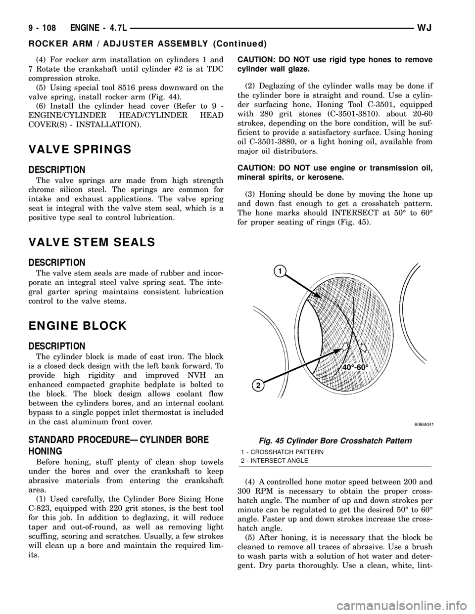
for proper seating of rings (Fig. 45).
(4) A controlled hone motor speed between 200 and
300 RPM is necessary to obtain the proper cross-
hatch angle. The number of up and down strokes per
minute can be regulated to get the desired 50É to 60É
angle. Faster up and down strokes increase the cross-
hatch angle.
(5) After honing, it is necessary that the block be
cleaned to remove all traces of abrasive. Use a brush
to wash parts with a solution of hot water and deter-
gent. Dry parts thoroughly. Use a clean, white, lint-
Fig. 45 Cylinder Bore Crosshatch Pattern
1 - CROSSHATCH PATTERN
2 - INTERSECT ANGLE
9 - 108 ENGINE - 4.7LWJ
ROCKER ARM / ADJUSTER ASSEMBLY (Continued)
Page 1353 of 2199
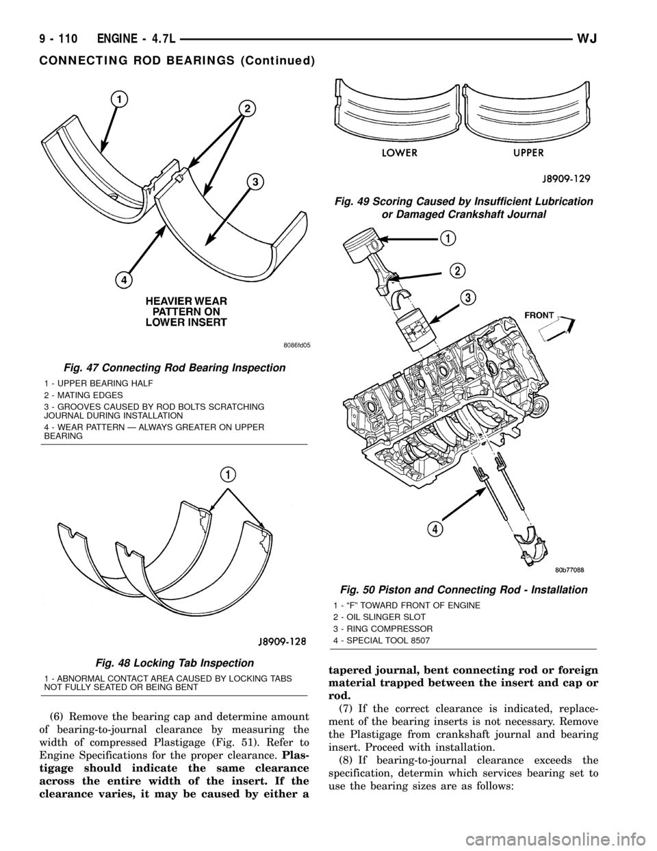
(6) Remove the bearing cap and determine amount
of bearing-to-journal clearance by measuring the
width of compressed Plastigage (Fig. 51). Refer to
Engine Specifications for the proper clearance.Plas-
tigage should indicate the same clearance
across the entire width of the insert. If the
clearance varies, it may be caused by either atapered journal, bent connecting rod or foreign
material trapped between the insert and cap or
rod.
(7) If the correct clearance is indicated, replace-
ment of the bearing inserts is not necessary. Remove
the Plastigage from crankshaft journal and bearing
insert. Proceed with installation.
(8) If bearing-to-journal clearance exceeds the
specification, determin which services bearing set to
use the bearing sizes are as follows:
Fig. 47 Connecting Rod Bearing Inspection
1 - UPPER BEARING HALF
2 - MATING EDGES
3 - GROOVES CAUSED BY ROD BOLTS SCRATCHING
JOURNAL DURING INSTALLATION
4 - WEAR PATTERN Ð ALWAYS GREATER ON UPPER
BEARING
Fig. 48 Locking Tab Inspection
1 - ABNORMAL CONTACT AREA CAUSED BY LOCKING TABS
NOT FULLY SEATED OR BEING BENT
Fig. 49 Scoring Caused by Insufficient Lubrication
or Damaged Crankshaft Journal
Fig. 50 Piston and Connecting Rod - Installation
1 - ªFº TOWARD FRONT OF ENGINE
2 - OIL SLINGER SLOT
3 - RING COMPRESSOR
4 - SPECIAL TOOL 8507
9 - 110 ENGINE - 4.7LWJ
CONNECTING ROD BEARINGS (Continued)
Page 1362 of 2199
REMOVAL) and (Refer to 9 - ENGINE/CYLINDER
HEAD/CYLINDER HEAD COVER(S) - REMOVAL).
²Timing chain cover (Refer to 9 - ENGINE/
VALVE TIMING/TIMING BELT / CHAIN COVER(S)
- REMOVAL).
²Cylinder head(s) (Refer to 9 - ENGINE/CYLIN-
DER HEAD - REMOVAL) and (Refer to 9 - ENGINE/
CYLINDER HEAD - REMOVAL).
(3) If necessary, remove top ridge of cylinder bores
with a reliable ridge reamer before removing pistons
from cylinder block.Be sure to keep tops of pis-
tons covered during this operation.Pistons and
connecting rods must be removed from top of cylinder
block. When removing piston and connecting rod
assemblies from the engine, rotate crankshaft so the
each connecting rod is centered in cylinder bore.
CAUTION: DO NOT use a number stamp or a punch
to mark connecting rods or caps, as damage to
connecting rods could occur
NOTE: Connecting rods and bearing caps are not
interchangeable and should be marked before
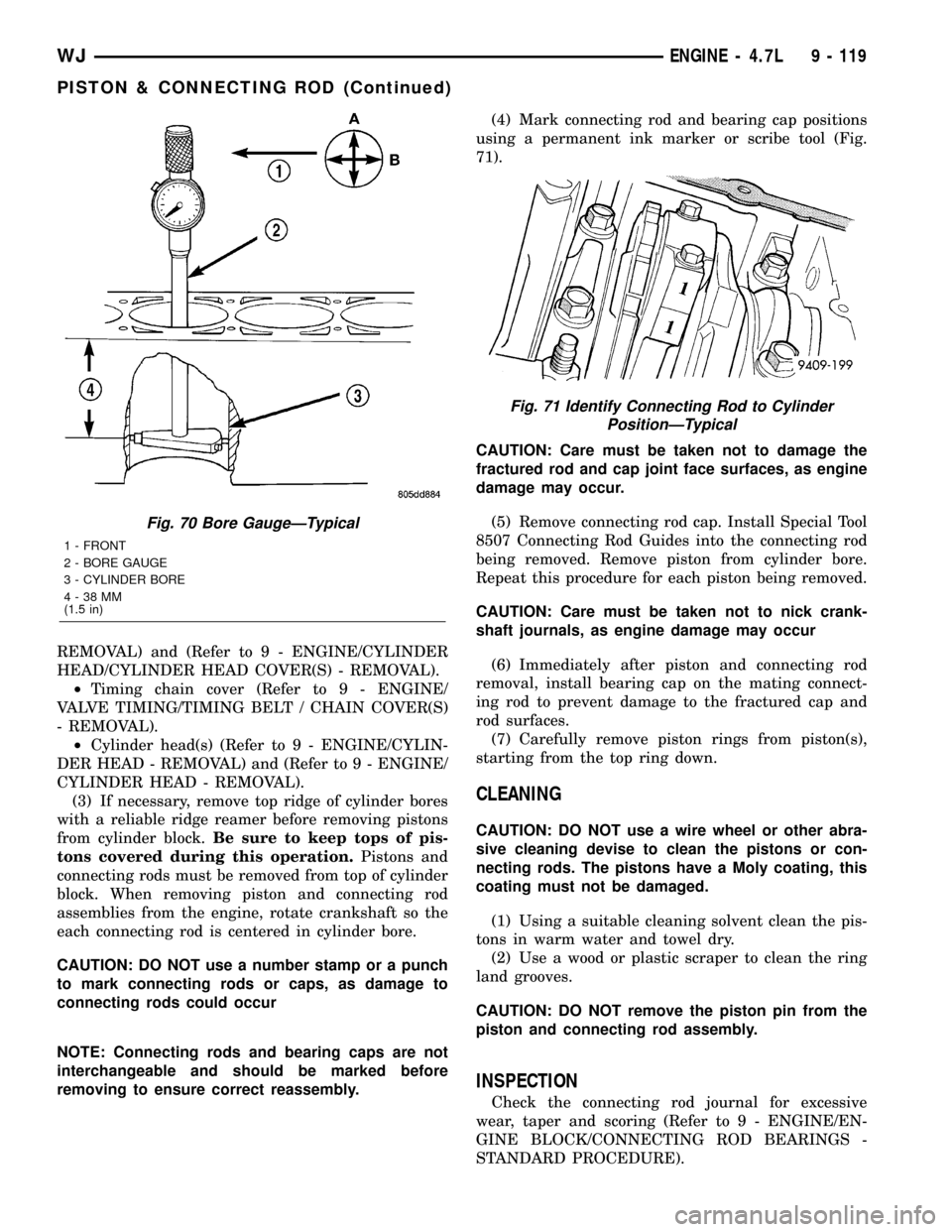
removing to ensure correct reassembly.(4) Mark connecting rod and bearing cap positions
using a permanent ink marker or scribe tool (Fig.
71).
CAUTION: Care must be taken not to damage the
fractured rod and cap joint face surfaces, as engine
damage may occur.
(5) Remove connecting rod cap. Install Special Tool
8507 Connecting Rod Guides into the connecting rod
being removed. Remove piston from cylinder bore.
Repeat this procedure for each piston being removed.
CAUTION: Care must be taken not to nick crank-
shaft journals, as engine damage may occur
(6) Immediately after piston and connecting rod
removal, install bearing cap on the mating connect-
ing rod to prevent damage to the fractured cap and
rod surfaces.
(7) Carefully remove piston rings from piston(s),
starting from the top ring down.
CLEANING
CAUTION: DO NOT use a wire wheel or other abra-
sive cleaning devise to clean the pistons or con-
necting rods. The pistons have a Moly coating, this
coating must not be damaged.
(1) Using a suitable cleaning solvent clean the pis-
tons in warm water and towel dry.
(2) Use a wood or plastic scraper to clean the ring
land grooves.
CAUTION: DO NOT remove the piston pin from the
piston and connecting rod assembly.
INSPECTION
Check the connecting rod journal for excessive
wear, taper and scoring (Refer to 9 - ENGINE/EN-
GINE BLOCK/CONNECTING ROD BEARINGS -
STANDARD PROCEDURE).
Fig. 70 Bore GaugeÐTypical
1 - FRONT
2 - BORE GAUGE
3 - CYLINDER BORE
4-38MM
(1.5 in)
Fig. 71 Identify Connecting Rod to Cylinder
PositionÐTypical
WJENGINE - 4.7L 9 - 119
PISTON & CONNECTING ROD (Continued)
Page 1363 of 2199
Check the connecting rod for signs of twist or bend-
ing.
Check the piston for taper and elliptical shape
before it is fitted into the cylinder bore (Refer to 9 -
ENGINE/ENGINE BLOCK/PISTON & CONNECT-
ING ROD - STANDARD PROCEDURE).
Check the piston for scoring, or scraping marks in
the piston skirts. Check the ring lands for cracks
and/or deterioration.
INSTALLATION
(1) Before installing piston and connecting rod
assemblies into the bore, install the piston rings.
(2)
Immerse the piston head and rings in clean
engine oil. Position a ring compressor over the piston
and rings. Tighten ring compressor.Ensure position
of rings do not change during this operation.
(3)Position bearing onto connecting rod. Ensure that
hole in bearing shell aligns with hole in connecting rod.
Lubricate bearing surface with clean engine oil.
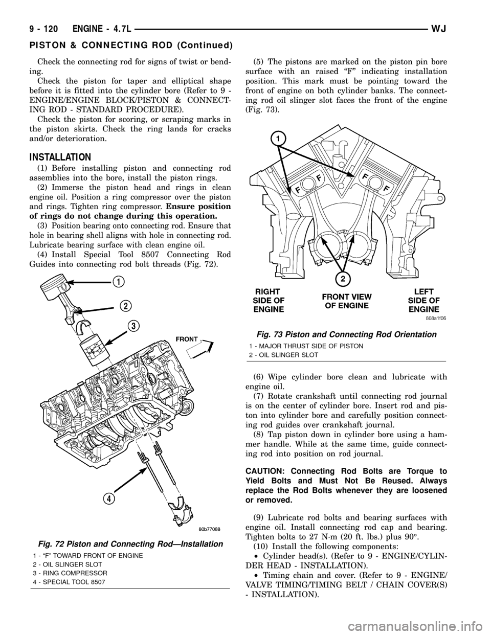
(4) Install Special Tool 8507 Connecting Rod
Guides into connecting rod bolt threads (Fig. 72).(5) The pistons are marked on the piston pin bore
surface with an raised ªFº indicating installation
position. This mark must be pointing toward the
front of engine on both cylinder banks. The connect-
ing rod oil slinger slot faces the front of the engine
(Fig. 73).
(6) Wipe cylinder bore clean and lubricate with
engine oil.
(7) Rotate crankshaft until connecting rod journal
is on the center of cylinder bore. Insert rod and pis-
ton into cylinder bore and carefully position connect-
ing rod guides over crankshaft journal.
(8) Tap piston down in cylinder bore using a ham-
mer handle. While at the same time, guide connect-
ing rod into position on rod journal.
CAUTION: Connecting Rod Bolts are Torque to
Yield Bolts and Must Not Be Reused. Always
replace the Rod Bolts whenever they are loosened
or removed.
(9) Lubricate rod bolts and bearing surfaces with
engine oil. Install connecting rod cap and bearing.
Tighten bolts to 27 N´m (20 ft. lbs.) plus 90É.
(10) Install the following components:
²Cylinder head(s). (Refer to 9 - ENGINE/CYLIN-
DER HEAD - INSTALLATION).
²Timing chain and cover. (Refer to 9 - ENGINE/
VALVE TIMING/TIMING BELT / CHAIN COVER(S)
- INSTALLATION).
Fig. 72 Piston and Connecting RodÐInstallation
1 - ªFº TOWARD FRONT OF ENGINE
2 - OIL SLINGER SLOT
3 - RING COMPRESSOR
4 - SPECIAL TOOL 8507
Fig. 73 Piston and Connecting Rod Orientation
1 - MAJOR THRUST SIDE OF PISTON
2 - OIL SLINGER SLOT
9 - 120 ENGINE - 4.7LWJ
PISTON & CONNECTING ROD (Continued)