tow JEEP GRAND CHEROKEE 2002 WJ / 2.G Owners Manual
[x] Cancel search | Manufacturer: JEEP, Model Year: 2002, Model line: GRAND CHEROKEE, Model: JEEP GRAND CHEROKEE 2002 WJ / 2.GPages: 2199, PDF Size: 76.01 MB
Page 1186 of 2199
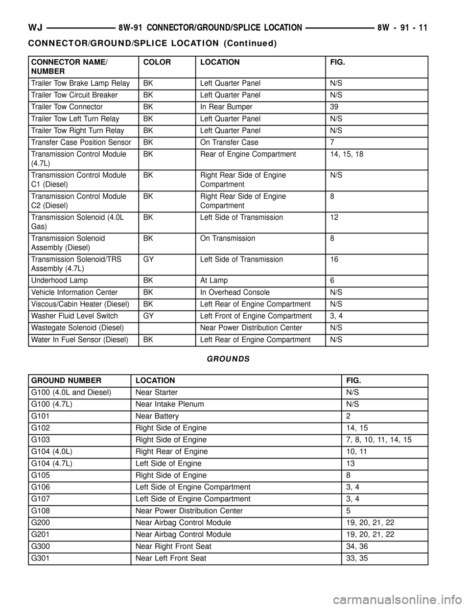
CONNECTOR NAME/
NUMBERCOLOR LOCATION FIG.
Trailer Tow Brake Lamp Relay BK Left Quarter Panel N/S
Trailer Tow Circuit Breaker BK Left Quarter Panel N/S
Trailer Tow Connector BK In Rear Bumper 39
Trailer Tow Left Turn Relay BK Left Quarter Panel N/S
Trailer Tow Right Turn Relay BK Left Quarter Panel N/S
Transfer Case Position Sensor BK On Transfer Case 7
Transmission Control Module
(4.7L)BK Rear of Engine Compartment 14, 15, 18
Transmission Control Module
C1 (Diesel)BK Right Rear Side of Engine
CompartmentN/S
Transmission Control Module
C2 (Diesel)BK Right Rear Side of Engine
Compartment8
Transmission Solenoid (4.0L
Gas)BK Left Side of Transmission 12
Transmission Solenoid
Assembly (Diesel)BK On Transmission 8
Transmission Solenoid/TRS
Assembly (4.7L)GY Left Side of Transmission 16
Underhood Lamp BK At Lamp 6
Vehicle Information Center BK In Overhead Console N/S
Viscous/Cabin Heater (Diesel) BK Left Rear of Engine Compartment N/S
Washer Fluid Level Switch GY Left Front of Engine Compartment 3, 4
Wastegate Solenoid (Diesel) Near Power Distribution Center N/S
Water In Fuel Sensor (Diesel) BK Left Rear of Engine Compartment N/S
GROUNDS
GROUND NUMBER LOCATION FIG.
G100 (4.0L and Diesel) Near Starter N/S
G100 (4.7L) Near Intake Plenum N/S
G101 Near Battery 2
G102 Right Side of Engine 14, 15
G103 Right Side of Engine 7, 8, 10, 11, 14, 15
G104 (4.0L) Right Rear of Engine 10, 11
G104 (4.7L) Left Side of Engine 13
G105 Right Side of Engine 8
G106 Left Side of Engine Compartment 3, 4
G107 Left Side of Engine Compartment 3, 4
G108 Near Power Distribution Center 5
G200 Near Airbag Control Module 19, 20, 21, 22
G201 Near Airbag Control Module 19, 20, 21, 22
G300 Near Right Front Seat 34, 36
G301 Near Left Front Seat 33, 35
WJ8W-91 CONNECTOR/GROUND/SPLICE LOCATION 8W - 91 - 11
CONNECTOR/GROUND/SPLICE LOCATION (Continued)
Page 1192 of 2199
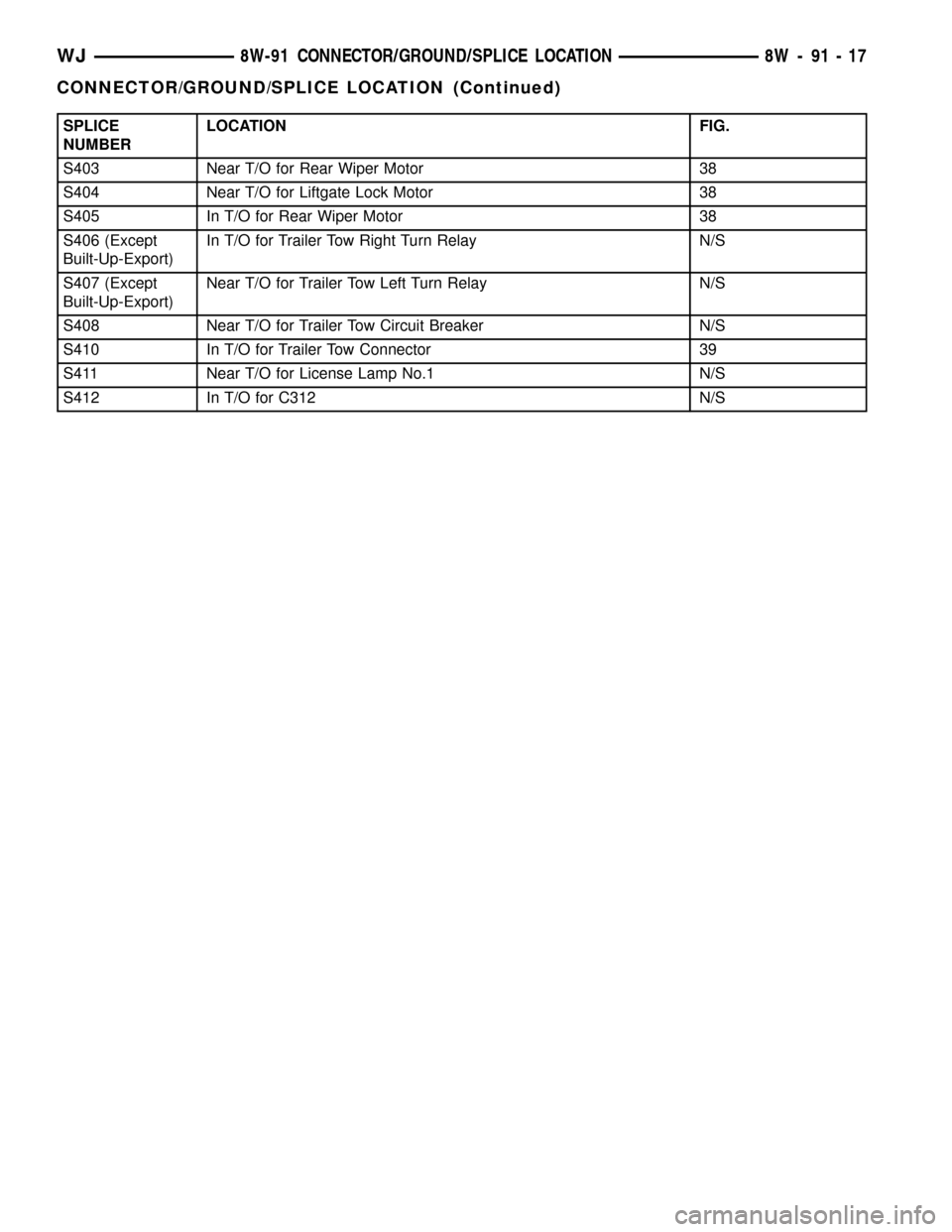
SPLICE
NUMBERLOCATION FIG.
S403 Near T/O for Rear Wiper Motor 38
S404 Near T/O for Liftgate Lock Motor 38
S405 In T/O for Rear Wiper Motor 38
S406 (Except
Built-Up-Export)In T/O for Trailer Tow Right Turn Relay N/S
S407 (Except
Built-Up-Export)Near T/O for Trailer Tow Left Turn Relay N/S
S408 Near T/O for Trailer Tow Circuit Breaker N/S
S410 In T/O for Trailer Tow Connector 39
S411 Near T/O for License Lamp No.1 N/S
S412 In T/O for C312 N/S
WJ8W-91 CONNECTOR/GROUND/SPLICE LOCATION 8W - 91 - 17
CONNECTOR/GROUND/SPLICE LOCATION (Continued)
Page 1225 of 2199
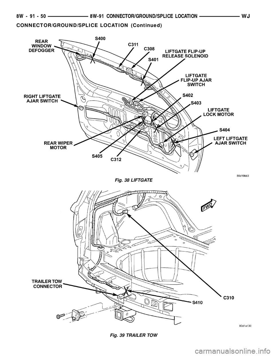
Fig. 38 LIFTGATE
Fig. 39 TRAILER TOW
8W - 91 - 50 8W-91 CONNECTOR/GROUND/SPLICE LOCATIONWJ
CONNECTOR/GROUND/SPLICE LOCATION (Continued)
Page 1227 of 2199

the same time, the power distribution system was
designed to provide ready access to these electrical
distribution points for the vehicle technician to use
when conducting diagnosis and repair of faulty cir-
cuits. The power distribution system can also prove
useful for the sourcing of additional electrical circuits
that may be required to provide the electrical current
needed to operate accessories that the vehicle owner
may choose to have installed in the aftermarket.
NOTE: DO NOT ATTEMPT TO SWAP POWER DIS-
TRIBUTION CENTERS FROM ONE VEHICLE TO
ANOTHER. MOST OF THESE ASSEMBLIES ARE
VEHICLE FEATURE SPECIFIC AND THEREFORE
NOT INTERCHANGEABLE. ALWAYS USE THE COR-
RECT PART NUMBERED ASSEMBLY WHEN DIAG-
NOSING OR REPLACING A POWER DISTRIBUTION
CENTER.
SPECIAL TOOLS
POWER DISTRIBUTION SYSTEMS
CIGAR LIGHTER OUTLET
DESCRIPTION
A cigar lighter outlet is standard equipment on
this model. On models equipped with the optional
Smoker's Package, the cigar lighter knob and heating
element are included. On models without the Smok-
er's Package, the cigar lighter outlet is equipped with
a snap fit plastic cap and is treated as an extra
accessory power outlet. The cigar lighter outlet is
installed in the instrument panel center lower bezel,
which is located near the bottom of the instrument
panel center stack area, below the heater and air
conditioner controls. The cigar lighter outlet is
secured by a snap fit within the center lower bezel.The cigar lighter outlet, plastic cap and the knob
and heating element unit are available for service
replacement. These components cannot be repaired
and, if faulty or damaged, they must be replaced.
OPERATION
The cigar lighter consists of two major components:
a knob and heating element unit, and the cigar
lighter base or outlet shell. The receptacle shell is
connected to ground, and an insulated contact in the
bottom of the shell is connected to battery current.
The cigar lighter receives battery voltage from a fuse
in the junction block when the ignition switch is in
the Accessory or On positions.
The cigar lighter knob and heating element are
encased within a spring-loaded housing, which also
features a sliding protective heat shield. When the
knob and heating element are inserted in the outlet
shell, the heating element resistor coil is grounded
through its housing to the outlet shell. If the cigar
lighter knob is pushed inward, the heat shield slides
up toward the knob exposing the heating element,
and the heating element extends from the housing
toward the insulated contact in the bottom of the
outlet shell.
Two small spring-clip retainers are located on
either side of the insulated contact inside the bottom
of the outlet shell. These clips engage and hold the
heating element against the insulated contact long
enough for the resistor coil to heat up. When the
heating element is engaged with the contact, battery
current can flow through the resistor coil to ground,
causing the resistor coil to heat.
When the resistor coil becomes sufficiently heated,
excess heat radiates from the heating element caus-
ing the spring-clips to expand. Once the spring-clips
expand far enough to release the heating element,
the spring-loaded housing forces the knob and heat-
ing element to pop back outward to their relaxed
position. When the cigar lighter knob and element
are pulled out of the outlet shell, the protective heat
shield slides downward on the housing so that the
heating element is recessed and shielded around its
circumference for safety.
DIAGNOSIS AND TESTING - CIGAR LIGHTER
OUTLET
For complete circuit diagrams, refer toHorn/Ci-
gar Lighter/Power Outletin Wiring Diagrams.
(1) Check the fused B(+) fuse in the junction block.
If OK, go to Step 2. If not OK, repair the shorted cir-
cuit or component as required and replace the faulty
fuse.
(2) Turn the ignition switch to the On position.
Check for battery voltage at the fused B(+) fuse in
Terminal Pick Kit 6680
8W - 97 - 2 8W-97 POWER DISTRIBUTIONWJ
POWER DISTRIBUTION (Continued)
Page 1234 of 2199
(9) Remove the PDC and the right headlamp and
dash wire harness from the engine compartment as a
unit.
DISASSEMBLY
POWER DISTRIBUTION CENTER DISASSEMBLY
PDC HOUSING LOWER COVER REMOVAL
The Power Distribution Center (PDC) cover, the
PDC housing lower cover, the PDC relay wedges, the
PDC relay cassettes and the PDC B(+) terminal stud
module are available for service replacement. The
PDC cover can be simply unlatched and removed
from the PDC housing without the PDC being
removed or disassembled. Service of the remaining
PDC components requires that the PDC be removed
from its mounting and disassembled. Refer toWiring
Repairin Wiring Diagrams for the location of the
wiring repair procedures.
(1) Remove the battery from the battery support.
Refer toBattery Systemfor the location of the bat-
tery removal procedures.
(2) Unlatch and remove the cover from the PDC.
(3) Remove the two nuts that secure the two-holed
eyelet of the battery wire harness PDC take out to
the B(+) terminal studs near the front of the PDC.
(4) Remove the battery wire harness PDC take out
eyelet from the two PDC B(+) terminal studs.
(5) Disengage the latches on the PDC housing
mounts from the tabs on the PDC mounting stan-
chions on the battery support, and pull the PDC
housing upward to disengage the mounts from the
stanchions.
(6) Where the right headlamp and dash wire har-
ness exits the PDC, remove the tape that secures the
wire harness to the trough formation on the PDC
housing lower cover.
(7) Using a trim stick or another suitable wide
flat-bladed tool, gently pry the latches on each side
and the front of the PDC housing that secure the
housing lower cover to the PDC and remove the
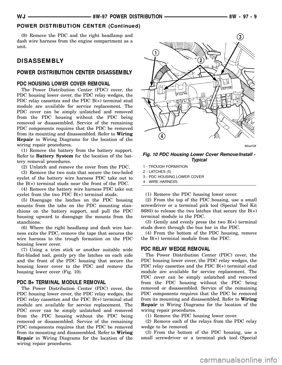
housing lower cover (Fig. 10).
PDC B+ TERMINAL MODULE REMOVAL
The Power Distribution Center (PDC) cover, the
PDC housing lower cover, the PDC relay wedges, the
PDC relay cassettes and the PDC B(+) terminal stud
module are available for service replacement. The
PDC cover can be simply unlatched and removed
from the PDC housing without the PDC being
removed or disassembled. Service of the remaining
PDC components requires that the PDC be removed
from its mounting and disassembled. Refer toWiring
Repairin Wiring Diagrams for the location of the
wiring repair procedures.(1) Remove the PDC housing lower cover.
(2) From the top of the PDC housing, use a small
screwdriver or a terminal pick tool (Special Tool Kit
6680) to release the two latches that secure the B(+)
terminal module in the PDC.
(3) Gently and evenly press the two B(+) terminal
studs down through the bus bar in the PDC.
(4) From the bottom of the PDC housing, remove
the B(+) terminal module from the PDC.
PDC RELAY WEDGE REMOVAL
The Power Distribution Center (PDC) cover, the
PDC housing lower cover, the PDC relay wedges, the
PDC relay cassettes and the PDC B(+) terminal stud
module are available for service replacement. The
PDC cover can be simply unlatched and removed
from the PDC housing without the PDC being
removed or disassembled. Service of the remaining
PDC components requires that the PDC be removed
from its mounting and disassembled. Refer toWiring
Repairin Wiring Diagrams for the location of the
wiring repair procedures.
(1) Remove the PDC housing lower cover.
(2) Remove each of the relays from the PDC relay
wedge to be removed.
(3) From the bottom of the PDC housing, use a
small screwdriver or a terminal pick tool (Special
Fig. 10 PDC Housing Lower Cover Remove/Install -
Typical
1 - TROUGH FORMATION
2 - LATCHES (5)
3 - PDC HOUSING LOWER COVER
4 - WIRE HARNESS
WJ8W-97 POWER DISTRIBUTION 8W - 97 - 9
POWER DISTRIBUTION CENTER (Continued)
Page 1235 of 2199
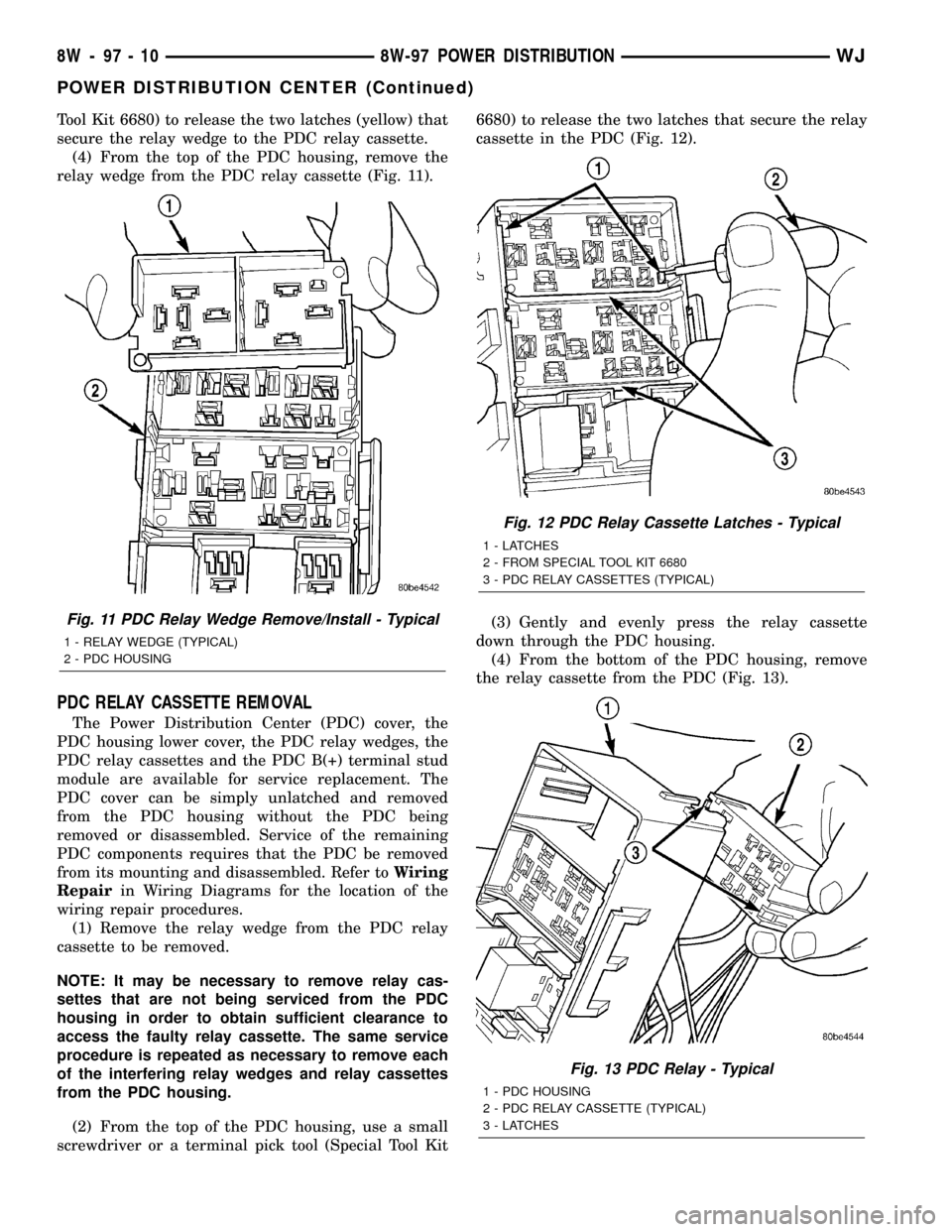
Tool Kit 6680) to release the two latches (yellow) that
secure the relay wedge to the PDC relay cassette.
(4) From the top of the PDC housing, remove the
relay wedge from the PDC relay cassette (Fig. 11).
PDC RELAY CASSETTE REMOVAL
The Power Distribution Center (PDC) cover, the
PDC housing lower cover, the PDC relay wedges, the
PDC relay cassettes and the PDC B(+) terminal stud
module are available for service replacement. The
PDC cover can be simply unlatched and removed
from the PDC housing without the PDC being
removed or disassembled. Service of the remaining
PDC components requires that the PDC be removed
from its mounting and disassembled. Refer toWiring
Repairin Wiring Diagrams for the location of the
wiring repair procedures.
(1) Remove the relay wedge from the PDC relay
cassette to be removed.
NOTE: It may be necessary to remove relay cas-
settes that are not being serviced from the PDC
housing in order to obtain sufficient clearance to
access the faulty relay cassette. The same service
procedure is repeated as necessary to remove each
of the interfering relay wedges and relay cassettes
from the PDC housing.
(2) From the top of the PDC housing, use a small
screwdriver or a terminal pick tool (Special Tool Kit6680) to release the two latches that secure the relay
cassette in the PDC (Fig. 12).
(3) Gently and evenly press the relay cassette
down through the PDC housing.
(4) From the bottom of the PDC housing, remove
the relay cassette from the PDC (Fig. 13).
Fig. 11 PDC Relay Wedge Remove/Install - Typical
1 - RELAY WEDGE (TYPICAL)
2 - PDC HOUSING
Fig. 12 PDC Relay Cassette Latches - Typical
1 - LATCHES
2 - FROM SPECIAL TOOL KIT 6680
3 - PDC RELAY CASSETTES (TYPICAL)
Fig. 13 PDC Relay - Typical
1 - PDC HOUSING
2 - PDC RELAY CASSETTE (TYPICAL)
3 - LATCHES
8W - 97 - 10 8W-97 POWER DISTRIBUTIONWJ
POWER DISTRIBUTION CENTER (Continued)
Page 1236 of 2199
CAUTION: Do not remove the wiring and terminals
from the terminal cavities of the faulty PDC relay
cassette at this time. Refer to the Assembly proce-
dure that follows for the proper procedures for
transferring the wiring and terminals to the replace-
ment PDC relay cassette.
ASSEMBLY
POWER DISTRIBUTION CENTER ASSEMBLY
PDC B(+) TERMINAL MODULE INSTALLATION
(1) From the bottom of the PDC housing, align and
insert the B(+) terminal module into the PDC.
(2) From the bottom of the PDC housing, align and
insert the two studs of the PDC B(+) terminal mod-
ule through the bus bar in the PDC.
(3) From the bottom of the PDC housing, press the
B(+) terminal module gently and evenly into the PDC
until both of the latches are fully engaged.
(4) Install the PDC housing lower cover.
RELAY WEDGE INSTALLATION
(1) From the top of the PDC housing, align and
insert the PDC relay wedge latch arms into the cor-
rect cavities in the relay cassette.
(2) Gently and evenly press the PDC relay wedge
down into the relay cassette until both of the latches
are fully engaged.
(3) Install each of the removed relays into the
proper cavities of the PDC relay wedge.
(4) Install the PDC housing lower cover.
RELAY CASSETTE INSTALLATION
(1) Move the faulty PDC relay cassette with its
wiring away from the bottom of the PDC housing far
enough to allow the replacement relay cassette to be
installed into the PDC.
(2) Using the faulty relay cassette as a guide, be
certain that the replacement relay cassette is cor-
rectly oriented before installing it into the PDC hous-
ing.
(3) From the bottom of the PDC housing, align and
insert the replacement relay cassette into the PDC.
Press the relay cassette up into the PDC until both
of the latches are fully engaged.
CAUTION: Proper care must be taken to be certain
that the wiring and terminals from the faulty PDC
relay cassette are installed in the correct terminal
cavities of the replacement relay cassette. To pre-
vent mistakes it is recommended that the wiring
and terminals be removed from the faulty relay cas-
sette one cavity at a time, repaired or spliced as
necessary, then installed securely into the correctcavity of the replacement relay cassette. If you are
not absolutely certain into which cavity a terminal
should be installed, refer to Power Distribution in
the index of this service manual for the location of
complete circuit diagrams covering the PDC.
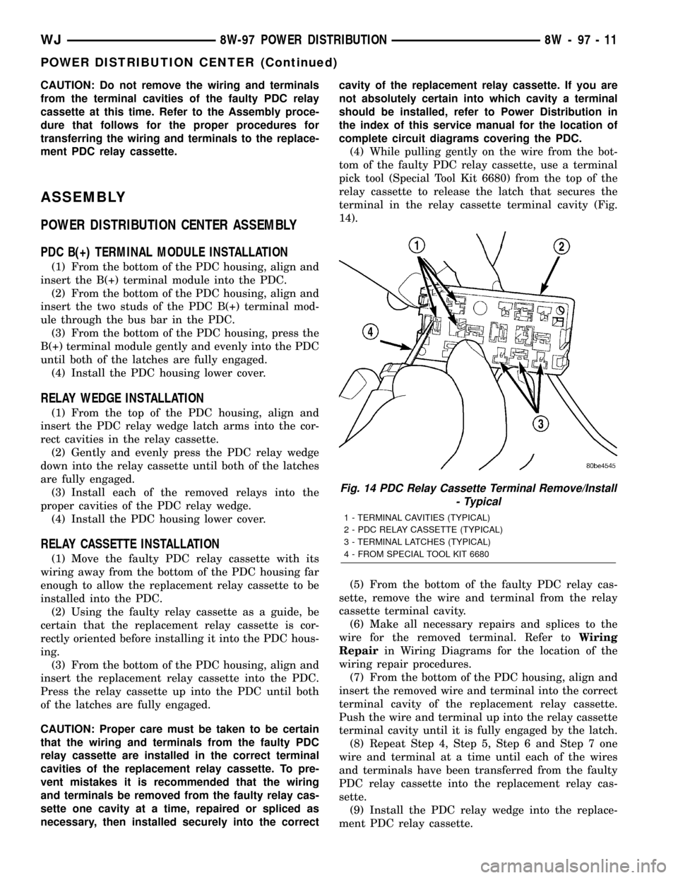
(4) While pulling gently on the wire from the bot-
tom of the faulty PDC relay cassette, use a terminal
pick tool (Special Tool Kit 6680) from the top of the
relay cassette to release the latch that secures the
terminal in the relay cassette terminal cavity (Fig.
14).
(5) From the bottom of the faulty PDC relay cas-
sette, remove the wire and terminal from the relay
cassette terminal cavity.
(6) Make all necessary repairs and splices to the
wire for the removed terminal. Refer toWiring
Repairin Wiring Diagrams for the location of the
wiring repair procedures.
(7) From the bottom of the PDC housing, align and
insert the removed wire and terminal into the correct
terminal cavity of the replacement relay cassette.
Push the wire and terminal up into the relay cassette
terminal cavity until it is fully engaged by the latch.
(8) Repeat Step 4, Step 5, Step 6 and Step 7 one
wire and terminal at a time until each of the wires
and terminals have been transferred from the faulty
PDC relay cassette into the replacement relay cas-
sette.
(9) Install the PDC relay wedge into the replace-
ment PDC relay cassette.
Fig. 14 PDC Relay Cassette Terminal Remove/Install
- Typical
1 - TERMINAL CAVITIES (TYPICAL)
2 - PDC RELAY CASSETTE (TYPICAL)
3 - TERMINAL LATCHES (TYPICAL)
4 - FROM SPECIAL TOOL KIT 6680
WJ8W-97 POWER DISTRIBUTION 8W - 97 - 11
POWER DISTRIBUTION CENTER (Continued)
Page 1241 of 2199
FuseandBatteryin the index in this service man-
ual for the location of additional service information
covering the ignition-off draw fuse and the battery.
FUSE COVER
REMOVAL
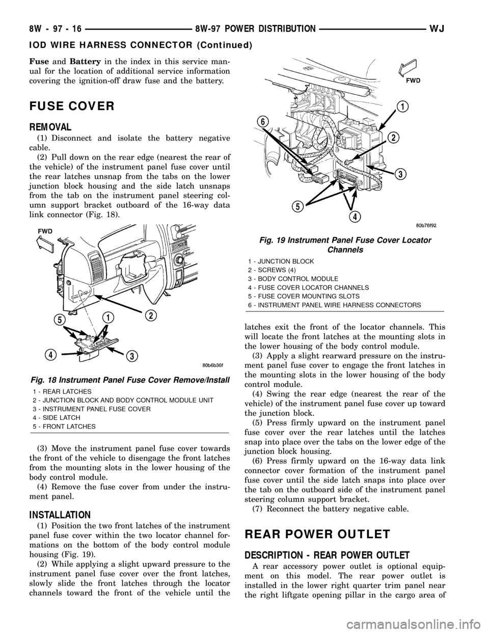
(1) Disconnect and isolate the battery negative
cable.
(2) Pull down on the rear edge (nearest the rear of
the vehicle) of the instrument panel fuse cover until
the rear latches unsnap from the tabs on the lower
junction block housing and the side latch unsnaps
from the tab on the instrument panel steering col-
umn support bracket outboard of the 16-way data
link connector (Fig. 18).
(3) Move the instrument panel fuse cover towards
the front of the vehicle to disengage the front latches
from the mounting slots in the lower housing of the
body control module.
(4) Remove the fuse cover from under the instru-
ment panel.
INSTALLATION
(1) Position the two front latches of the instrument
panel fuse cover within the two locator channel for-
mations on the bottom of the body control module
housing (Fig. 19).
(2) While applying a slight upward pressure to the
instrument panel fuse cover over the front latches,
slowly slide the front latches through the locator
channels toward the front of the vehicle until thelatches exit the front of the locator channels. This
will locate the front latches at the mounting slots in
the lower housing of the body control module.
(3) Apply a slight rearward pressure on the instru-
ment panel fuse cover to engage the front latches in
the mounting slots in the lower housing of the body
control module.
(4) Swing the rear edge (nearest the rear of the
vehicle) of the instrument panel fuse cover up toward
the junction block.
(5) Press firmly upward on the instrument panel
fuse cover over the rear latches until the latches
snap into place over the tabs on the lower edge of the
junction block housing.
(6) Press firmly upward on the 16-way data link
connector cover formation of the instrument panel
fuse cover until the side latch snaps into place over
the tab on the outboard side of the instrument panel
steering column support bracket.
(7) Reconnect the battery negative cable.
REAR POWER OUTLET
DESCRIPTION - REAR POWER OUTLET
A rear accessory power outlet is optional equip-
ment on this model. The rear power outlet is
installed in the lower right quarter trim panel near
the right liftgate opening pillar in the cargo area of
Fig. 18 Instrument Panel Fuse Cover Remove/Install
1 - REAR LATCHES
2 - JUNCTION BLOCK AND BODY CONTROL MODULE UNIT
3 - INSTRUMENT PANEL FUSE COVER
4 - SIDE LATCH
5 - FRONT LATCHES
Fig. 19 Instrument Panel Fuse Cover Locator
Channels
1 - JUNCTION BLOCK
2 - SCREWS (4)
3 - BODY CONTROL MODULE
4 - FUSE COVER LOCATOR CHANNELS
5 - FUSE COVER MOUNTING SLOTS
6 - INSTRUMENT PANEL WIRE HARNESS CONNECTORS
8W - 97 - 16 8W-97 POWER DISTRIBUTIONWJ
IOD WIRE HARNESS CONNECTOR (Continued)
Page 1253 of 2199

FORM-IN-PLACE GASKET AND SEALER
APPLICATION
Assembling parts using a form-in-place gasket
requires care but it's easier then using precut gaskets.
MopartGasket Maker material should be applied
sparingly 1 mm (0.040 in.) diameter or less of sealant
to one gasket surface. Be certain the material sur-
rounds each mounting hole. Excess material can eas-
ily be wiped off. Components should be torqued in
place within 15 minutes. The use of a locating dowel
is recommended during assembly to prevent smear-
ing material off the location.
MopartEngine RTV GEN II or ATF RTV gasket
material should be applied in a continuous bead
approximately 3 mm (0.120 in.) in diameter. All
mounting holes must be circled. For corner sealing, a
3.17 or 6.35 mm (1/8 or 1/4 in.) drop is placed in the
center of the gasket contact area. Uncured sealant
may be removed with a shop towel. Components
should be torqued in place while the sealant is still
wet to the touch (within 10 minutes). The usage of a
locating dowel is recommended during assembly to
prevent smearing material off the location.
MopartGasket Sealant in an aerosol can should be
applied using a thin, even coat sprayed completely
over both surfaces to be joined, and both sides of a
gasket. Then proceed with assembly. Material in a
can w/applicator can be brushed on evenly over the
sealing surfaces. Material in an aerosol can should be
used on engines with multi-layer steel gaskets.
STANDARD PROCEDURE - REPAIR DAMAGED
OR WORN THREADS
CAUTION: Be sure that the tapped holes maintain
the original center line.
Damaged or worn threads can be repaired. Essen-
tially, this repair consists of:
²Drilling out worn or damaged threads.
²Tapping the hole with a special Heli-Coil Tap, or
equivalent.
²Installing an insert into the tapped hole to bring
the hole back to its original thread size.
STANDARD PROCEDUREÐHYDROSTATIC LOCK
CAUTION: DO NOT use the starter motor to rotate
the crankshaft. Severe damage could occur.
When an engine is suspected of hydrostatic lock
(regardless of what caused the problem), follow the
steps below.
(1) Perform the Fuel Pressure Release Procedure
(Refer to 14 - FUEL SYSTEM/FUEL DELIVERY -
STANDARD PROCEDURE).(2) Disconnect the negative cable(s) from the bat-
tery.
(3) Inspect air cleaner, induction system, and
intake manifold to ensure system is dry and clear of
foreign material.
(4) Place a shop towel around the spark plugs to
catch any fluid that may possibly be under pressure
in the cylinder head. Remove the spark plugs.
(5) With all spark plugs removed, rotate the crank-
shaft using a breaker bar and socket.
(6) Identify the fluid in the cylinders (coolant, fuel,
oil, etc.).
(7) Be sure all fluid has been removed from the
cylinders.
(8) Repair engine or components as necessary to
prevent this problem from occurring again.
(9) Squirt a small amount of engine oil into the
cylinders to lubricate the walls. This will prevent
damage on restart.
(10) Install new spark plugs. Tighten the spark
plugs to 41 N´m (30 ft. lbs.) torque.
(11) Drain engine oil. Remove and discard the oil
filter.
(12) Install the drain plug. Tighten the plug to 34
N´m (25 ft. lbs.) torque.
(13) Install a new oil filter.
(14) Fill engine crankcase with the specified
amount and grade of oil. (Refer to LUBRICATION &
MAINTENANCE - SPECIFICATIONS).
(15) Connect the negative cable(s) to the battery.
(16) Start the engine and check for any leaks.
STANDARD PROCEDURE - CYLINDER BORE
HONING
Before honing, stuff plenty of clean shop towels
under the bores and over the crankshaft to keep
abrasive materials from entering the crankshaft
area.
(1)
Used carefully, the Cylinder Bore Sizing Hone
C-823, equipped with 220 grit stones, is the best tool
for this job. In addition to deglazing, it will reduce
taper and out-of-round, as well as removing light scuff-
ing, scoring and scratches. Usually, a few strokes will
clean up a bore and maintain the required limits.
CAUTION: DO NOT use rigid type hones to remove
cylinder wall glaze.
(2) Deglazing of the cylinder walls may be done if
the cylinder bore is straight and round. Use a cylin-
der surfacing hone, Honing Tool C-3501, equipped
with 280 grit stones (C-3501-3810). about 20-60
strokes, depending on the bore condition, will be suf-
ficient to provide a satisfactory surface. Using honing
oil C-3501-3880, or a light honing oil, available from
major oil distributors.
9 - 10 ENGINE - 4.0LWJ
ENGINE - 4.0L (Continued)
Page 1263 of 2199

(2) Drain the coolant (Refer to 7 - COOLING -
STANDARD PROCEDURE) and disconnect the hoses
at the engine thermostat housing and the water
pump inlet. DO NOT waste reusable coolant. If the
solution is clean and is being drained only to service
the engine or cooling system, drain the coolant into a
clean container for reuse.
(3) Remove the air cleaner assembly (Refer to 9 -
ENGINE/AIR INTAKE SYSTEM/AIR CLEANER
HOUSING - REMOVAL).
(4) Remove the cylinder head cover (Refer to 9 -
ENGINE/CYLINDER HEAD/CYLINDER HEAD
COVER(S) - REMOVAL).
(5) Remove the capscrews, bridge and pivot assem-
blies and rocker arms (Refer to 9 - ENGINE/CYLIN-
DER HEAD/ROCKER ARM / ADJUSTER ASSY -
REMOVAL).
(6) Remove the push rods.Retain the push rods,
bridges, pivots and rocker arms in the same
order as removed.
(7) Remove the accessory drive belt (Refer to 7 -
COOLING/ACCESSORY DRIVE/DRIVE BELTS -
REMOVAL).
(8) Remove the A/C compressor mounting bolts
and secure the compressor to the side.
(9) Remove the power steering pump and bracket
from the intake manifold and water pump. Set the
pump and bracket aside. DO NOT disconnect the
hoses.
(10) Perform the Fuel System Pressure Release
procedure. (Refer to 14 - FUEL SYSTEM/FUEL
DELIVERY - STANDARD PROCEDURE).
(11) Disconnect the fuel supply line at the fuel rail.(12) Remove the intake and exhaust manifolds
from the engine cylinder head (Refer to 9 - ENGINE/
MANIFOLDS/INTAKE MANIFOLD - REMOVAL).
(13) Remove the coil rail (Refer to 8 - ELECTRI-
CAL/IGNITION CONTROL/COIL RAIL - REMOV-
AL).
(14) Remove spark plugs (Refer to 8 - ELECTRI-
CAL/IGNITION CONTROL/SPARK PLUG - REMOV-
AL).
(15) Disconnect the temperature sending unit wire
connector.
(16) Remove the engine cylinder head bolts. Bolt
No.14 cannot be removed until the head is moved for-
ward (Fig. 9). Pull bolt No.14 out as far as it will go
and then suspend the bolt in this position (tape
around the bolt).
(17) Remove the engine cylinder head and gasket
(Fig. 9).
(18) If this was the first time the bolts were
removed, put a paint dab on the top of the bolt. If the
bolts have a paint dab on the top of the bolt or it
isn't known if they were used before, discard the
bolts.
(19) Stuff clean lint free shop towels into the cyl-
inder bores.
NOTE: If the valves, springs, or seals are to be
inspected/replaced at this time, (Refer to 9 -
ENGINE/CYLINDER HEAD/INTAKE/EXHAUST
VALVES & SEATS - STANDARD PROCEDURE) for
proper inspection procedures.
Fig. 8 Cylinder Head 4.0L Engine
1 - CYLINDER HEAD BOLTS
2 - CYLINDER HEAD GASKET
3 - CYLINDER HEAD
Fig. 9 Engine Cylinder
1 - CYLINDER HEAD BOLTS
2 - CYLINDER HEAD GASKET
3 - CYLINDER HEAD
9 - 20 ENGINE - 4.0LWJ
CYLINDER HEAD (Continued)