Signal JEEP GRAND CHEROKEE 2002 WJ / 2.G Workshop Manual
[x] Cancel search | Manufacturer: JEEP, Model Year: 2002, Model line: GRAND CHEROKEE, Model: JEEP GRAND CHEROKEE 2002 WJ / 2.GPages: 2199, PDF Size: 76.01 MB
Page 1169 of 2199
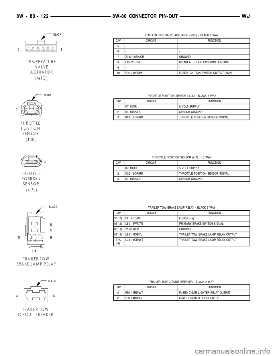
TEMPERATURE VALVE ACTUATOR (MTC) - BLACK 6 WAY
CAV CIRCUIT FUNCTION
5- -
6- -
7 Z132 20BK/OR GROUND
8 C67 20RD/LB BLEND AIR DOOR POSITION CONTROL
9- -
10 F22 20WT/PK FUSED IGNITION SWITCH OUTPUT (RUN)
THROTTLE POSITION SENSOR (4.0L) - BLACK 3 WAY
CAV CIRCUIT FUNCTION
1 K7 18OR 5 VOLT SUPPLY
2 K4 18BK/LB SENSOR GROUND
3 K22 18OR/RD THROTTLE POSITION SENSOR SIGNAL
THROTTLE POSITION SENSOR (4.7L)-3WAY
CAV CIRCUIT FUNCTION
1 K7 18OR 5 VOLT SUPPLY
2 K22 18OR/RD THROTTLE POSITION SENSOR SIGNAL
3 K4 18BK/LB SENSOR GROUND
TRAILER TOW BRAKE LAMP RELAY - BLACK 5 WAY
CAV CIRCUIT FUNCTION
30 (3) F9 14RD/BK FUSED B(+)
85 (2) L50 18WT/TN PRIMARY BRAKE SWITCH SIGNAL
86 (1) Z150 18BK GROUND
87 (5) L95 14DG/YL TRAILER TOW BRAKE LAMP RELAY OUTPUT
87A
(4)L94 14OR/WT TRAILER TOW BRAKE LAMP RELAY OUTPUT
TRAILER TOW CIRCUIT BREAKER - BLACK 2 WAY
CAV CIRCUIT FUNCTION
A F30 14RD/WT FUSED CIGAR LIGHTER RELAY OUTPUT
B F30 14RD/TN CIGAR LIGHTER RELAY OUTPUT
8W - 80 - 122 8W-80 CONNECTOR PIN-OUTWJ
Page 1170 of 2199
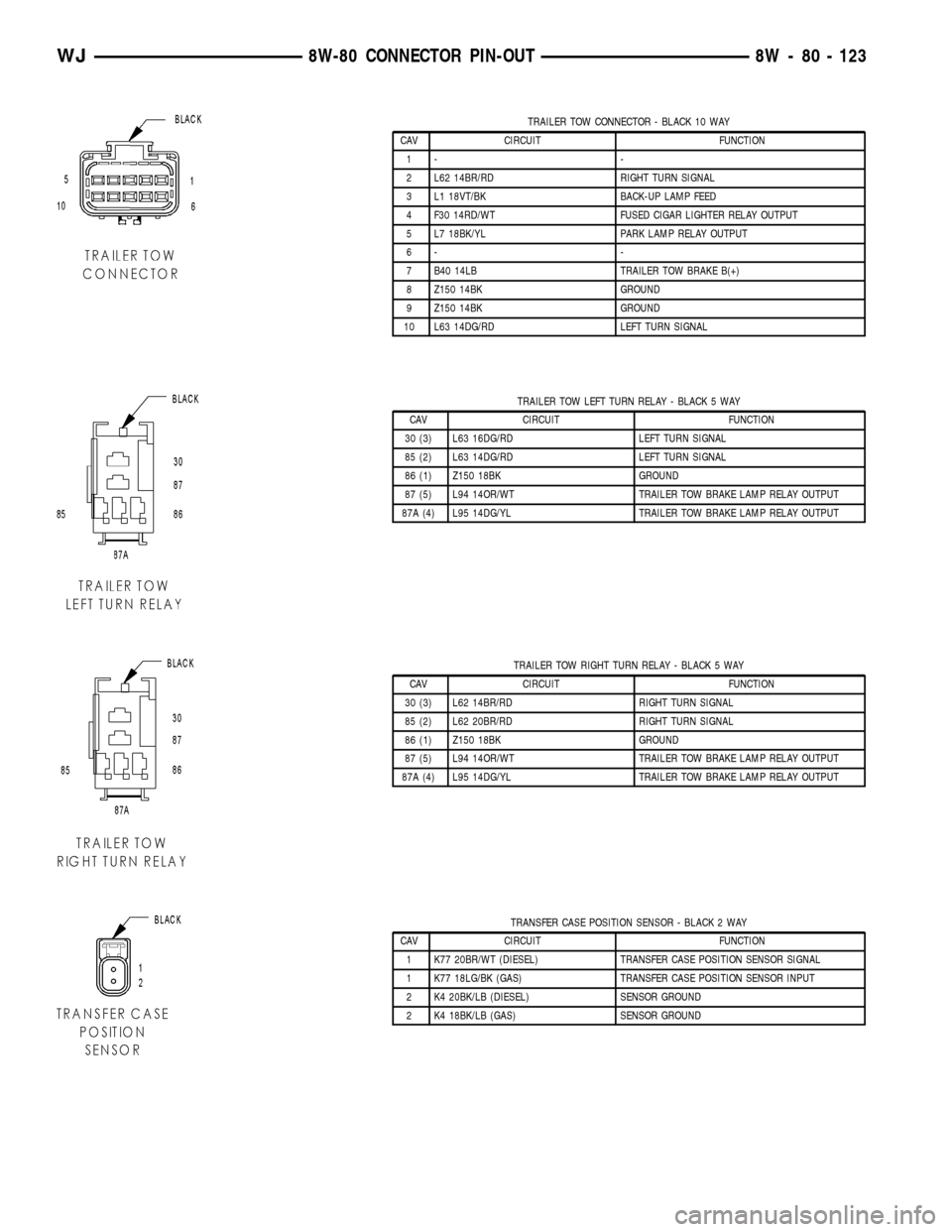
TRAILER TOW CONNECTOR - BLACK 10 WAY
CAV CIRCUIT FUNCTION
1- -
2 L62 14BR/RD RIGHT TURN SIGNAL
3 L1 18VT/BK BACK-UP LAMP FEED
4 F30 14RD/WT FUSED CIGAR LIGHTER RELAY OUTPUT
5 L7 18BK/YL PARK LAMP RELAY OUTPUT
6- -
7 B40 14LB TRAILER TOW BRAKE B(+)
8 Z150 14BK GROUND
9 Z150 14BK GROUND
10 L63 14DG/RD LEFT TURN SIGNAL
TRAILER TOW LEFT TURN RELAY - BLACK 5 WAY
CAV CIRCUIT FUNCTION
30 (3) L63 16DG/RD LEFT TURN SIGNAL
85 (2) L63 14DG/RD LEFT TURN SIGNAL
86 (1) Z150 18BK GROUND
87 (5) L94 14OR/WT TRAILER TOW BRAKE LAMP RELAY OUTPUT
87A (4) L95 14DG/YL TRAILER TOW BRAKE LAMP RELAY OUTPUT
TRAILER TOW RIGHT TURN RELAY - BLACK 5 WAY
CAV CIRCUIT FUNCTION
30 (3) L62 14BR/RD RIGHT TURN SIGNAL
85 (2) L62 20BR/RD RIGHT TURN SIGNAL
86 (1) Z150 18BK GROUND
87 (5) L94 14OR/WT TRAILER TOW BRAKE LAMP RELAY OUTPUT
87A (4) L95 14DG/YL TRAILER TOW BRAKE LAMP RELAY OUTPUT
TRANSFER CASE POSITION SENSOR - BLACK 2 WAY
CAV CIRCUIT FUNCTION
1 K77 20BR/WT (DIESEL) TRANSFER CASE POSITION SENSOR SIGNAL
1 K77 18LG/BK (GAS) TRANSFER CASE POSITION SENSOR INPUT
2 K4 20BK/LB (DIESEL) SENSOR GROUND
2 K4 18BK/LB (GAS) SENSOR GROUND
WJ8W-80 CONNECTOR PIN-OUT 8W - 80 - 123
Page 1171 of 2199
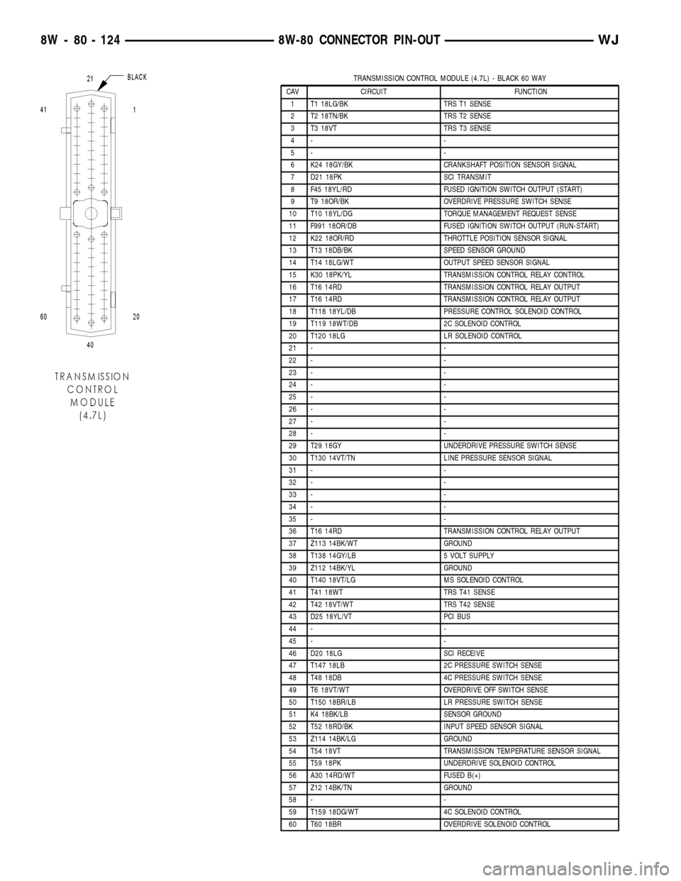
TRANSMISSION CONTROL MODULE (4.7L) - BLACK 60 WAY
CAV CIRCUIT FUNCTION
1 T1 18LG/BK TRS T1 SENSE
2 T2 18TN/BK TRS T2 SENSE
3 T3 18VT TRS T3 SENSE
4- -
5- -
6 K24 18GY/BK CRANKSHAFT POSITION SENSOR SIGNAL
7 D21 18PK SCI TRANSMIT
8 F45 18YL/RD FUSED IGNITION SWITCH OUTPUT (START)
9 T9 18OR/BK OVERDRIVE PRESSURE SWITCH SENSE
10 T10 18YL/DG TORQUE MANAGEMENT REQUEST SENSE
11 F991 18OR/DB FUSED IGNITION SWITCH OUTPUT (RUN-START)
12 K22 18OR/RD THROTTLE POSITION SENSOR SIGNAL
13 T13 18DB/BK SPEED SENSOR GROUND
14 T14 18LG/WT OUTPUT SPEED SENSOR SIGNAL
15 K30 18PK/YL TRANSMISSION CONTROL RELAY CONTROL
16 T16 14RD TRANSMISSION CONTROL RELAY OUTPUT
17 T16 14RD TRANSMISSION CONTROL RELAY OUTPUT
18 T118 18YL/DB PRESSURE CONTROL SOLENOID CONTROL
19 T119 18WT/DB 2C SOLENOID CONTROL
20 T120 18LG LR SOLENOID CONTROL
21 - -
22 - -
23 - -
24 - -
25 - -
26 - -
27 - -
28 - -
29 T29 18GY UNDERDRIVE PRESSURE SWITCH SENSE
30 T130 14VT/TN LINE PRESSURE SENSOR SIGNAL
31 - -
32 - -
33 - -
34 - -
35 - -
36 T16 14RD TRANSMISSION CONTROL RELAY OUTPUT
37 Z113 14BK/WT GROUND
38 T138 14GY/LB 5 VOLT SUPPLY
39 Z112 14BK/YL GROUND
40 T140 18VT/LG MS SOLENOID CONTROL
41 T41 18WT TRS T41 SENSE
42 T42 18VT/WT TRS T42 SENSE
43 D25 18YL/VT PCI BUS
44 - -
45 - -
46 D20 18LG SCI RECEIVE
47 T147 18LB 2C PRESSURE SWITCH SENSE
48 T48 18DB 4C PRESSURE SWITCH SENSE
49 T6 18VT/WT OVERDRIVE OFF SWITCH SENSE
50 T150 18BR/LB LR PRESSURE SWITCH SENSE
51 K4 18BK/LB SENSOR GROUND
52 T52 18RD/BK INPUT SPEED SENSOR SIGNAL
53 Z114 14BK/LG GROUND
54 T54 18VT TRANSMISSION TEMPERATURE SENSOR SIGNAL
55 T59 18PK UNDERDRIVE SOLENOID CONTROL
56 A30 14RD/WT FUSED B(+)
57 Z12 14BK/TN GROUND
58 - -
59 T159 18DG/WT 4C SOLENOID CONTROL
60 T60 18BR OVERDRIVE SOLENOID CONTROL
8W - 80 - 124 8W-80 CONNECTOR PIN-OUTWJ
Page 1172 of 2199
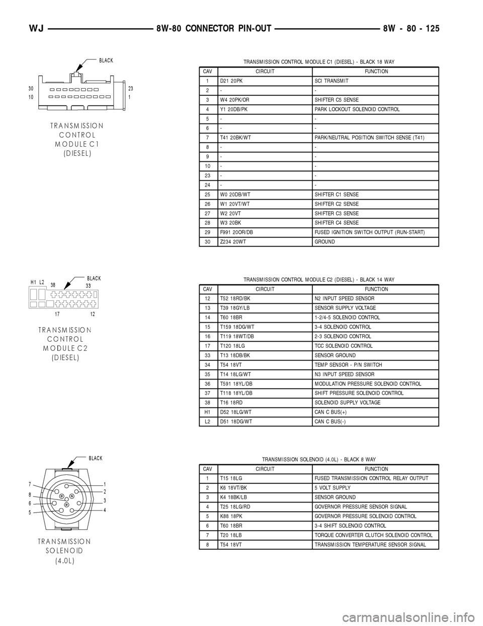
TRANSMISSION CONTROL MODULE C1 (DIESEL) - BLACK 18 WAY
CAV CIRCUIT FUNCTION
1 D21 20PK SCI TRANSMIT
2- -
3 W4 20PK/OR SHIFTER C5 SENSE
4 Y1 20DB/PK PARK LOCKOUT SOLENOID CONTROL
5- -
6- -
7 T41 20BK/WT PARK/NEUTRAL POSITION SWITCH SENSE (T41)
8- -
9- -
10 - -
23 - -
24 - -
25 W0 20DB/WT SHIFTER C1 SENSE
26 W1 20VT/WT SHIFTER C2 SENSE
27 W2 20VT SHIFTER C3 SENSE
28 W3 20BK SHIFTER C4 SENSE
29 F991 20OR/DB FUSED IGNITION SWITCH OUTPUT (RUN-START)
30 Z234 20WT GROUND
TRANSMISSION CONTROL MODULE C2 (DIESEL) - BLACK 14 WAY
CAV CIRCUIT FUNCTION
12 T52 18RD/BK N2 INPUT SPEED SENSOR
13 T39 18GY/LB SENSOR SUPPLY VOLTAGE
14 T60 18BR 1-2/4-5 SOLENOID CONTROL
15 T159 18DG/WT 3-4 SOLENOID CONTROL
16 T119 18WT/DB 2-3 SOLENOID CONTROL
17 T120 18LG TCC SOLENOID CONTROL
33 T13 18DB/BK SENSOR GROUND
34 T54 18VT TEMP SENSOR - P/N SWITCH
35 T14 18LG/WT N3 INPUT SPEED SENSOR
36 T591 18YL/DB MODULATION PRESSURE SOLENOID CONTROL
37 T118 18YL/DB SHIFT PRESSURE SOLENOID CONTROL
38 T16 18RD SOLENOID SUPPLY VOLTAGE
H1 D52 18LG/WT CAN C BUS(+)
L2 D51 18DG/WT CAN C BUS(-)
TRANSMISSION SOLENOID (4.0L) - BLACK 8 WAY
CAV CIRCUIT FUNCTION
1 T15 18LG FUSED TRANSMISSION CONTROL RELAY OUTPUT
2 K6 18VT/BK 5 VOLT SUPPLY
3 K4 18BK/LB SENSOR GROUND
4 T25 18LG/RD GOVERNOR PRESSURE SENSOR SIGNAL
5 K88 18PK GOVERNOR PRESSURE SOLENOID CONTROL
6 T60 18BR 3-4 SHIFT SOLENOID CONTROL
7 T20 18LB TORQUE CONVERTER CLUTCH SOLENOID CONTROL
8 T54 18VT TRANSMISSION TEMPERATURE SENSOR SIGNAL
WJ8W-80 CONNECTOR PIN-OUT 8W - 80 - 125
Page 1173 of 2199
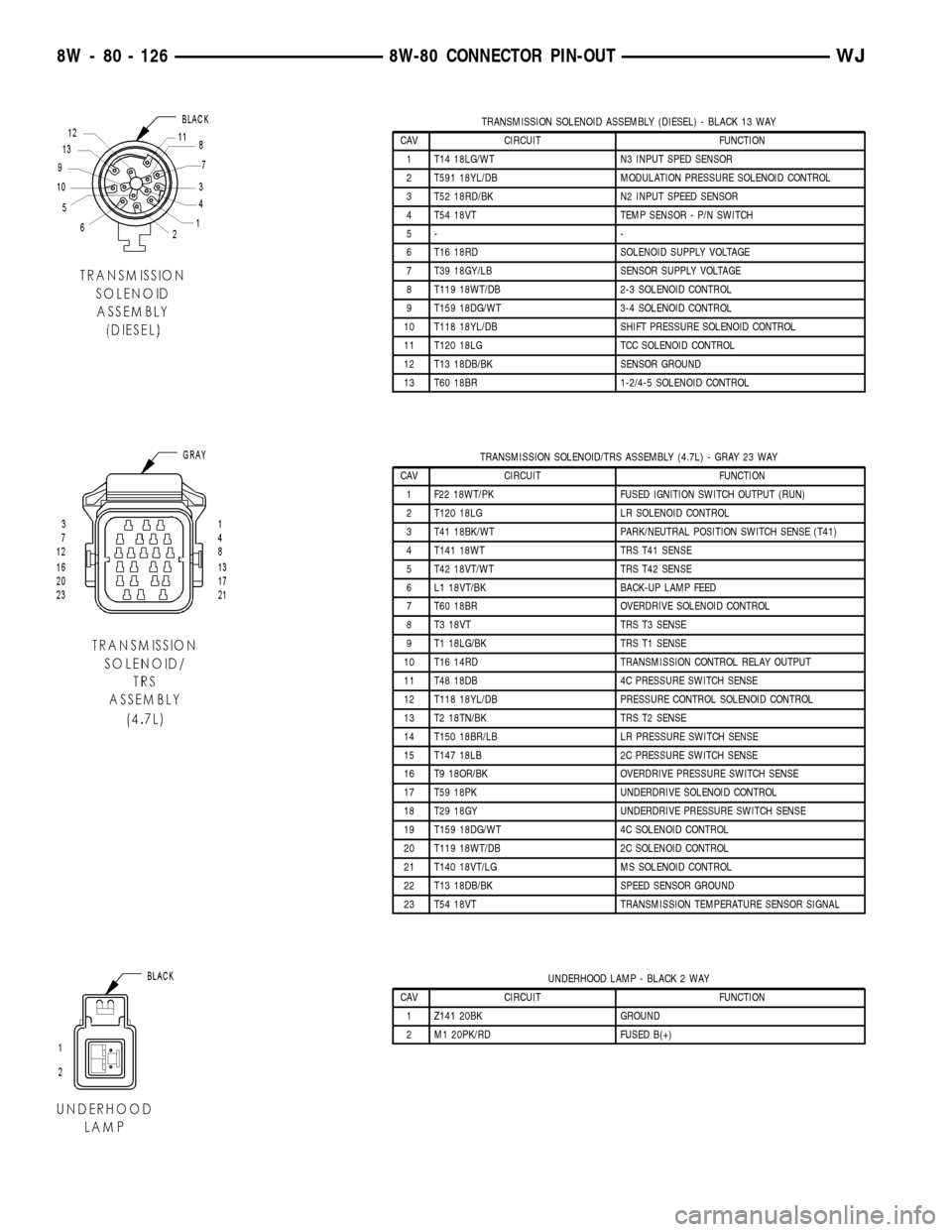
TRANSMISSION SOLENOID ASSEMBLY (DIESEL) - BLACK 13 WAY
CAV CIRCUIT FUNCTION
1 T14 18LG/WT N3 INPUT SPED SENSOR
2 T591 18YL/DB MODULATION PRESSURE SOLENOID CONTROL
3 T52 18RD/BK N2 INPUT SPEED SENSOR
4 T54 18VT TEMP SENSOR - P/N SWITCH
5- -
6 T16 18RD SOLENOID SUPPLY VOLTAGE
7 T39 18GY/LB SENSOR SUPPLY VOLTAGE
8 T119 18WT/DB 2-3 SOLENOID CONTROL
9 T159 18DG/WT 3-4 SOLENOID CONTROL
10 T118 18YL/DB SHIFT PRESSURE SOLENOID CONTROL
11 T120 18LG TCC SOLENOID CONTROL
12 T13 18DB/BK SENSOR GROUND
13 T60 18BR 1-2/4-5 SOLENOID CONTROL
TRANSMISSION SOLENOID/TRS ASSEMBLY (4.7L) - GRAY 23 WAY
CAV CIRCUIT FUNCTION
1 F22 18WT/PK FUSED IGNITION SWITCH OUTPUT (RUN)
2 T120 18LG LR SOLENOID CONTROL
3 T41 18BK/WT PARK/NEUTRAL POSITION SWITCH SENSE (T41)
4 T141 18WT TRS T41 SENSE
5 T42 18VT/WT TRS T42 SENSE
6 L1 18VT/BK BACK-UP LAMP FEED
7 T60 18BR OVERDRIVE SOLENOID CONTROL
8 T3 18VT TRS T3 SENSE
9 T1 18LG/BK TRS T1 SENSE
10 T16 14RD TRANSMISSION CONTROL RELAY OUTPUT
11 T48 18DB 4C PRESSURE SWITCH SENSE
12 T118 18YL/DB PRESSURE CONTROL SOLENOID CONTROL
13 T2 18TN/BK TRS T2 SENSE
14 T150 18BR/LB LR PRESSURE SWITCH SENSE
15 T147 18LB 2C PRESSURE SWITCH SENSE
16 T9 18OR/BK OVERDRIVE PRESSURE SWITCH SENSE
17 T59 18PK UNDERDRIVE SOLENOID CONTROL
18 T29 18GY UNDERDRIVE PRESSURE SWITCH SENSE
19 T159 18DG/WT 4C SOLENOID CONTROL
20 T119 18WT/DB 2C SOLENOID CONTROL
21 T140 18VT/LG MS SOLENOID CONTROL
22 T13 18DB/BK SPEED SENSOR GROUND
23 T54 18VT TRANSMISSION TEMPERATURE SENSOR SIGNAL
UNDERHOOD LAMP - BLACK 2 WAY
CAV CIRCUIT FUNCTION
1 Z141 20BK GROUND
2 M1 20PK/RD FUSED B(+)
8W - 80 - 126 8W-80 CONNECTOR PIN-OUTWJ
Page 1174 of 2199
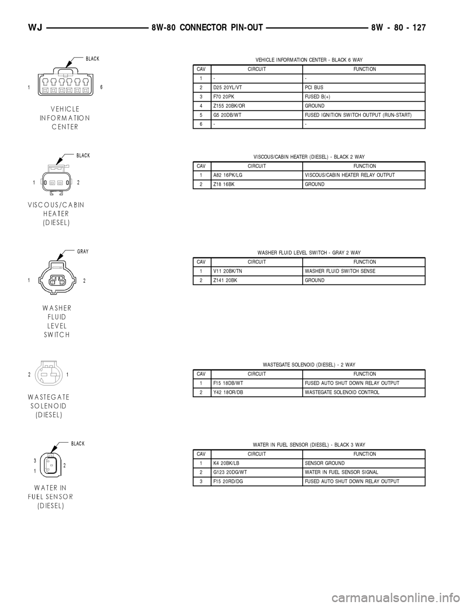
VEHICLE INFORMATION CENTER - BLACK 6 WAY
CAV CIRCUIT FUNCTION
1- -
2 D25 20YL/VT PCI BUS
3 F70 20PK FUSED B(+)
4 Z155 20BK/OR GROUND
5 G5 20DB/WT FUSED IGNITION SWITCH OUTPUT (RUN-START)
6- -
VISCOUS/CABIN HEATER (DIESEL) - BLACK 2 WAY
CAV CIRCUIT FUNCTION
1 A82 16PK/LG VISCOUS/CABIN HEATER RELAY OUTPUT
2 Z18 16BK GROUND
WASHER FLUID LEVEL SWITCH - GRAY 2 WAY
CAV CIRCUIT FUNCTION
1 V11 20BK/TN WASHER FLUID SWITCH SENSE
2 Z141 20BK GROUND
WASTEGATE SOLENOID (DIESEL)-2WAY
CAV CIRCUIT FUNCTION
1 F15 18DB/WT FUSED AUTO SHUT DOWN RELAY OUTPUT
2 Y42 18OR/DB WASTEGATE SOLENOID CONTROL
WATER IN FUEL SENSOR (DIESEL) - BLACK 3 WAY
CAV CIRCUIT FUNCTION
1 K4 20BK/LB SENSOR GROUND
2 G123 20DG/WT WATER IN FUEL SENSOR SIGNAL
3 F15 20RD/DG FUSED AUTO SHUT DOWN RELAY OUTPUT
WJ8W-80 CONNECTOR PIN-OUT 8W - 80 - 127
Page 1182 of 2199
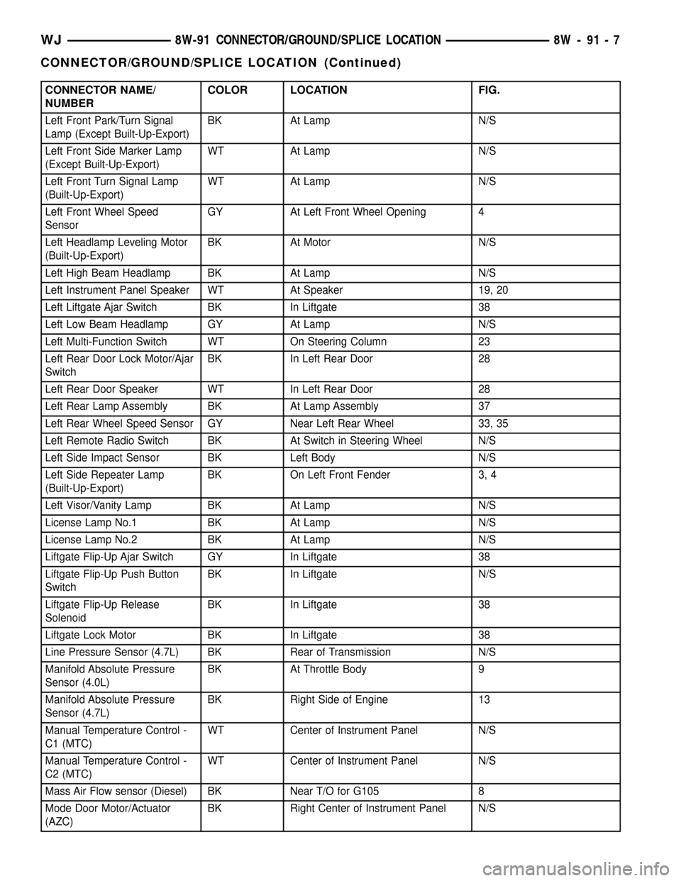
CONNECTOR NAME/
NUMBERCOLOR LOCATION FIG.
Left Front Park/Turn Signal
Lamp (Except Built-Up-Export)BK At Lamp N/S
Left Front Side Marker Lamp
(Except Built-Up-Export)WT At Lamp N/S
Left Front Turn Signal Lamp
(Built-Up-Export)WT At Lamp N/S
Left Front Wheel Speed
SensorGY At Left Front Wheel Opening 4
Left Headlamp Leveling Motor
(Built-Up-Export)BK At Motor N/S
Left High Beam Headlamp BK At Lamp N/S
Left Instrument Panel Speaker WT At Speaker 19, 20
Left Liftgate Ajar Switch BK In Liftgate 38
Left Low Beam Headlamp GY At Lamp N/S
Left Multi-Function Switch WT On Steering Column 23
Left Rear Door Lock Motor/Ajar
SwitchBK In Left Rear Door 28
Left Rear Door Speaker WT In Left Rear Door 28
Left Rear Lamp Assembly BK At Lamp Assembly 37
Left Rear Wheel Speed Sensor GY Near Left Rear Wheel 33, 35
Left Remote Radio Switch BK At Switch in Steering Wheel N/S
Left Side Impact Sensor BK Left Body N/S
Left Side Repeater Lamp
(Built-Up-Export)BK On Left Front Fender 3, 4
Left Visor/Vanity Lamp BK At Lamp N/S
License Lamp No.1 BK At Lamp N/S
License Lamp No.2 BK At Lamp N/S
Liftgate Flip-Up Ajar Switch GY In Liftgate 38
Liftgate Flip-Up Push Button
SwitchBK In Liftgate N/S
Liftgate Flip-Up Release
SolenoidBK In Liftgate 38
Liftgate Lock Motor BK In Liftgate 38
Line Pressure Sensor (4.7L) BK Rear of Transmission N/S
Manifold Absolute Pressure
Sensor (4.0L)BK At Throttle Body 9
Manifold Absolute Pressure
Sensor (4.7L)BK Right Side of Engine 13
Manual Temperature Control -
C1 (MTC)WT Center of Instrument Panel N/S
Manual Temperature Control -
C2 (MTC)WT Center of Instrument Panel N/S
Mass Air Flow sensor (Diesel) BK Near T/O for G105 8
Mode Door Motor/Actuator
(AZC)BK Right Center of Instrument Panel N/S
WJ8W-91 CONNECTOR/GROUND/SPLICE LOCATION 8W - 91 - 7
CONNECTOR/GROUND/SPLICE LOCATION (Continued)
Page 1185 of 2199
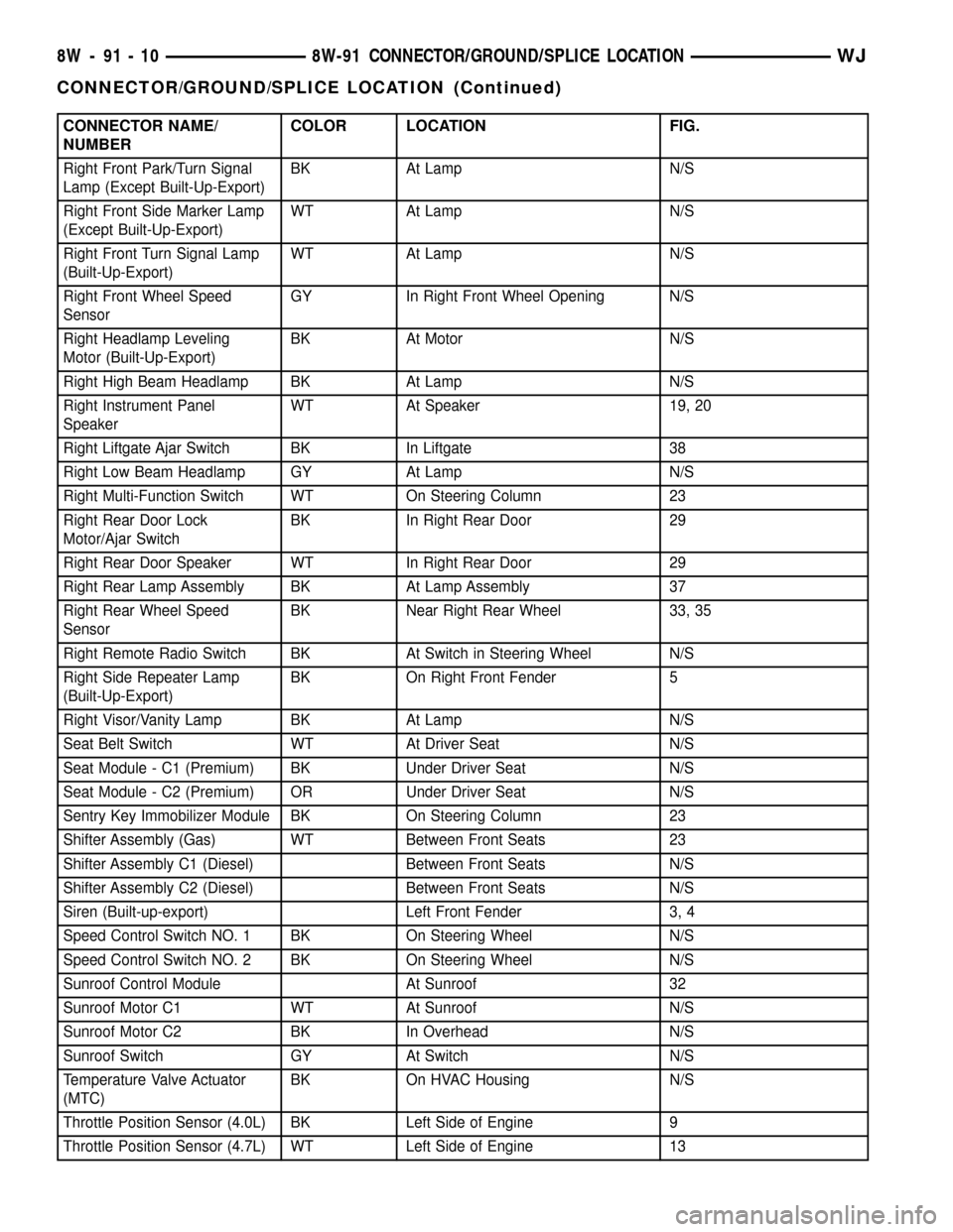
CONNECTOR NAME/
NUMBERCOLOR LOCATION FIG.
Right Front Park/Turn Signal
Lamp (Except Built-Up-Export)BK At Lamp N/S
Right Front Side Marker Lamp
(Except Built-Up-Export)WT At Lamp N/S
Right Front Turn Signal Lamp
(Built-Up-Export)WT At Lamp N/S
Right Front Wheel Speed
SensorGY In Right Front Wheel Opening N/S
Right Headlamp Leveling
Motor (Built-Up-Export)BK At Motor N/S
Right High Beam Headlamp BK At Lamp N/S
Right Instrument Panel
SpeakerWT At Speaker 19, 20
Right Liftgate Ajar Switch BK In Liftgate 38
Right Low Beam Headlamp GY At Lamp N/S
Right Multi-Function Switch WT On Steering Column 23
Right Rear Door Lock
Motor/Ajar SwitchBK In Right Rear Door 29
Right Rear Door Speaker WT In Right Rear Door 29
Right Rear Lamp Assembly BK At Lamp Assembly 37
Right Rear Wheel Speed
SensorBK Near Right Rear Wheel 33, 35
Right Remote Radio Switch BK At Switch in Steering Wheel N/S
Right Side Repeater Lamp
(Built-Up-Export)BK On Right Front Fender 5
Right Visor/Vanity Lamp BK At Lamp N/S
Seat Belt Switch WT At Driver Seat N/S
Seat Module - C1 (Premium) BK Under Driver Seat N/S
Seat Module - C2 (Premium) OR Under Driver Seat N/S
Sentry Key Immobilizer Module BK On Steering Column 23
Shifter Assembly (Gas) WT Between Front Seats 23
Shifter Assembly C1 (Diesel) Between Front Seats N/S
Shifter Assembly C2 (Diesel) Between Front Seats N/S
Siren (Built-up-export) Left Front Fender 3, 4
Speed Control Switch NO. 1 BK On Steering Wheel N/S
Speed Control Switch NO. 2 BK On Steering Wheel N/S
Sunroof Control Module At Sunroof 32
Sunroof Motor C1 WT At Sunroof N/S
Sunroof Motor C2 BK In Overhead N/S
Sunroof Switch GY At Switch N/S
Temperature Valve Actuator
(MTC)BK On HVAC Housing N/S
Throttle Position Sensor (4.0L) BK Left Side of Engine 9
Throttle Position Sensor (4.7L) WT Left Side of Engine 13
8W - 91 - 10 8W-91 CONNECTOR/GROUND/SPLICE LOCATIONWJ
CONNECTOR/GROUND/SPLICE LOCATION (Continued)
Page 1299 of 2199

(9) Lower the engine until it is properly located on
the engine mounts.
(10) Install the through bolts and tighten the nuts.
(11) Lower the jack stand and remove the piece of
wood.
(12) Install the engine flywheel and transmission
torque converter housing access cover.
(13) Install the engine starter motor. (Refer to 8 -
ELECTRICAL/STARTING/STARTER MOTOR -
INSTALLATION).
(14) Connect the exhaust pipe to the hanger and to
the engine exhaust manifold.
(15) Install transmission oil cooling lines (if
equipped) and oxygen sensor wiring supports that
attach to the oil pan studs.
(16) Install the oil pan drain plug (Fig. 81).
Tighten the plug to 34 N´m (25 ft. lbs.) torque.
(17) Lower the vehicle.
(18) Connect negative cable to battery.
(19) Fill the oil pan with engine oil to the specified
level.
WARNING: USE EXTREME CAUTION WHEN THE
ENGINE IS OPERATING. DO NOT STAND IN A
DIRECT LINE WITH THE FAN. DO NOT PUT YOUR
HANDS NEAR THE PULLEYS, BELTS OR FAN. DO
NOT WEAR LOOSE CLOTHING.
(20) Start the engine and inspect for leaks.
ENGINE OIL PRESSURE
SENSOR
DESCRIPTION
The 3±wire, solid-state engine oil pressure sensor
(sending unit) is located in an engine oil pressure
gallery.
OPERATION
The oil pressure sensor uses three circuits. They
are:
²A 5±volt power supply from the Powertrain Con-
trol Module (PCM)
²A sensor ground through the PCM's sensor
return
²A signal to the PCM relating to engine oil pres-
sure
The oil pressure sensor has a 3±wire electrical
function very much like the Manifold Absolute Pres-
sure (MAP) sensor. Meaning different pressures
relate to different output voltages.
A 5±volt supply is sent to the sensor from the PCM
to power up the sensor. The sensor returns a voltage
signal back to the PCM relating to engine oil pres-
sure. This signal is then transferred (bussed) to theinstrument panel on either a CCD or PCI bus circuit
(depending on vehicle line) to operate the oil pressure
gauge and the check gauges lamp. Ground for the
sensor is provided by the PCM through a low-noise
sensor return.
OIL PUMP
REMOVAL
A gear-type oil pump is mounted at the underside
of the cylinder block opposite the No.4 main bearing.
(1) Drain the engine oil.
(2) Remove the oil pan (Refer to 9 - ENGINE/LU-
BRICATION/OIL PAN - REMOVAL).
(3) Remove the pump-to-cylinder block attaching
bolts. Remove the pump assembly with gasket (Fig.
82).
CAUTION: If the oil pump is not to be serviced, DO
NOT disturb position of oil inlet tube and strainer
assembly in pump body. If the tube is moved within
the pump body, a replacement tube and strainer
assembly must be installed to assure an airtight
seal.
Fig. 82 Oil Pump Assembly
1 - OIL FILTER ADAPTOR
2 - BLOCK
3 - GASKET
4 - OIL INLET TUBE
5 - OIL PUMP
6 - STRAINER ASSEMBLY
7 - ATTACHING BOLTS
9 - 56 ENGINE - 4.0LWJ
OIL PAN (Continued)
Page 1376 of 2199

NOTE: When installing oil pan gasket/windage tray,
start four pan bolts at each corner before tightening
oil pickup tube. This will keep pan gasket in align-
ment.
(3) Install oil pump pick-up tube using a new
O-ring. First tighten bolt at O-ring end of tube to 28
N´m (20 ft. lbs.). Tighten remain tube support fasten-
ers to 28 N´m (20 ft. lbs.).
(4) Install oil pan and tighten fasteners to 15 N´m
(11 ft. lbs.) (Fig. 95).
(5) Reconnect transmission oil cooler lines to oil
pan stud bolt.
(6) Install starter (Refer to 8 - ELECTRICAL/
STARTING/STARTER MOTOR - INSTALLATION).
(7) Install exhaust system Y-pipe.
(8) Install structural cover (Refer to 9 - ENGINE/
ENGINE BLOCK/STRUCTURAL COVER - INSTAL-
LATION).
(9) Lower vehicle.
(10) Fill engine with proper amount of oil (Refer to
LUBRICATION & MAINTENANCE/FLUID TYPES -
SPECIFICATIONS).
(11) Connect negative cable to battery.
OIL PRESSURE SENSOR/
SWITCH
DESCRIPTION
The 3±wire, solid-state engine oil pressure sensor
(sending unit) is located in an engine oil pressure
gallery.
OPERATION
The oil pressure sensor uses three circuits. They are:
²A 5±volt power supply from the Powertrain Con-
trol Module (PCM)
²A sensor ground through the PCM's sensor
return
²
A signal to the PCM relating to engine oil pressure
The oil pressure sensor has a 3±wire electrical
function very much like the Manifold Absolute Pres-
sure (MAP) sensor. Meaning different pressures
relate to different output voltages.
A 5±volt supply is sent to the sensor from the PCM
to power up the sensor. The sensor returns a voltage
signal back to the PCM relating to engine oil pres-
sure. This signal is then transferred (bussed) to the
instrument panel on either a CCD or PCI bus circuit
(depending on vehicle line) to operate the oil pressure
gauge and the check gauges lamp. Ground for the
sensor is provided by the PCM through a low-noise
sensor return.
REMOVAL
(1) Disconnect the negative cable from the battery.
(2) Raise vehicle on hoist.
(3) Remove front splash shield.
(4) Disconnect oil pressure sender wire (Fig. 96).
(5) Remove the pressure sender (Fig. 96).
INSTALLATION
(1) Install oil pressure sender.
(2) Connect oil pressure sender wire.
(3) Install front splash shield.
(4) Lower vehicle.
(5) Connect the negative battery cable.
Fig. 95 Oil Pan Tightening Sequence
Fig. 96 Oil Pressure Sending Unit
1 - BELT
2 - OIL PRESSURE SENSOR
3 - OIL FILTER
4 - ELEC. CONNECTOR
WJENGINE - 4.7L 9 - 133
OIL PAN (Continued)