Signal JEEP GRAND CHEROKEE 2002 WJ / 2.G Workshop Manual
[x] Cancel search | Manufacturer: JEEP, Model Year: 2002, Model line: GRAND CHEROKEE, Model: JEEP GRAND CHEROKEE 2002 WJ / 2.GPages: 2199, PDF Size: 76.01 MB
Page 2161 of 2199
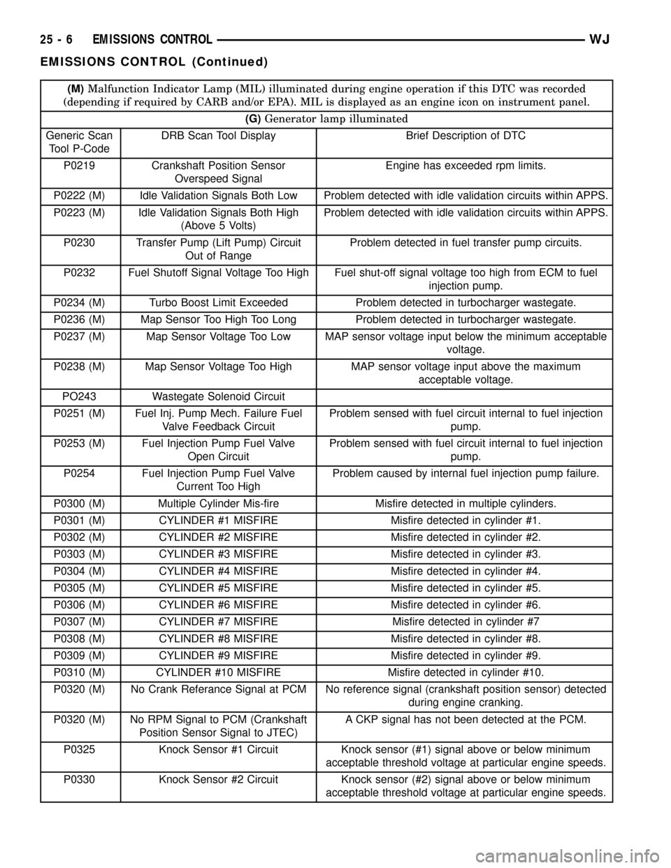
(M)Malfunction Indicator Lamp (MIL) illuminated during engine operation if this DTC was recorded
(depending if required by CARB and/or EPA). MIL is displayed as an engine icon on instrument panel.
(G)Generator lamp illuminated
Generic Scan
Tool P-CodeDRB Scan Tool Display Brief Description of DTC
P0219 Crankshaft Position Sensor
Overspeed SignalEngine has exceeded rpm limits.
P0222 (M) Idle Validation Signals Both Low Problem detected with idle validation circuits within APPS.
P0223 (M) Idle Validation Signals Both High
(Above 5 Volts)Problem detected with idle validation circuits within APPS.
P0230 Transfer Pump (Lift Pump) Circuit
Out of RangeProblem detected in fuel transfer pump circuits.
P0232 Fuel Shutoff Signal Voltage Too High Fuel shut-off signal voltage too high from ECM to fuel
injection pump.
P0234 (M) Turbo Boost Limit Exceeded Problem detected in turbocharger wastegate.
P0236 (M) Map Sensor Too High Too Long Problem detected in turbocharger wastegate.
P0237 (M) Map Sensor Voltage Too Low MAP sensor voltage input below the minimum acceptable
voltage.
P0238 (M) Map Sensor Voltage Too High MAP sensor voltage input above the maximum
acceptable voltage.
PO243 Wastegate Solenoid Circuit
P0251 (M) Fuel Inj. Pump Mech. Failure Fuel
Valve Feedback CircuitProblem sensed with fuel circuit internal to fuel injection
pump.
P0253 (M) Fuel Injection Pump Fuel Valve
Open CircuitProblem sensed with fuel circuit internal to fuel injection
pump.
P0254 Fuel Injection Pump Fuel Valve
Current Too HighProblem caused by internal fuel injection pump failure.
P0300 (M) Multiple Cylinder Mis-fire Misfire detected in multiple cylinders.
P0301 (M) CYLINDER #1 MISFIRE Misfire detected in cylinder #1.
P0302 (M) CYLINDER #2 MISFIRE Misfire detected in cylinder #2.
P0303 (M) CYLINDER #3 MISFIRE Misfire detected in cylinder #3.
P0304 (M) CYLINDER #4 MISFIRE Misfire detected in cylinder #4.
P0305 (M) CYLINDER #5 MISFIRE Misfire detected in cylinder #5.
P0306 (M) CYLINDER #6 MISFIRE Misfire detected in cylinder #6.
P0307 (M) CYLINDER #7 MISFIRE Misfire detected in cylinder #7
P0308 (M) CYLINDER #8 MISFIRE Misfire detected in cylinder #8.
P0309 (M) CYLINDER #9 MISFIRE Misfire detected in cylinder #9.
P0310 (M) CYLINDER #10 MISFIRE Misfire detected in cylinder #10.
P0320 (M) No Crank Referance Signal at PCM No reference signal (crankshaft position sensor) detected
during engine cranking.
P0320 (M) No RPM Signal to PCM (Crankshaft
Position Sensor Signal to JTEC)A CKP signal has not been detected at the PCM.
P0325 Knock Sensor #1 Circuit Knock sensor (#1) signal above or below minimum
acceptable threshold voltage at particular engine speeds.
P0330 Knock Sensor #2 Circuit Knock sensor (#2) signal above or below minimum
acceptable threshold voltage at particular engine speeds.
25 - 6 EMISSIONS CONTROLWJ
EMISSIONS CONTROL (Continued)
Page 2162 of 2199
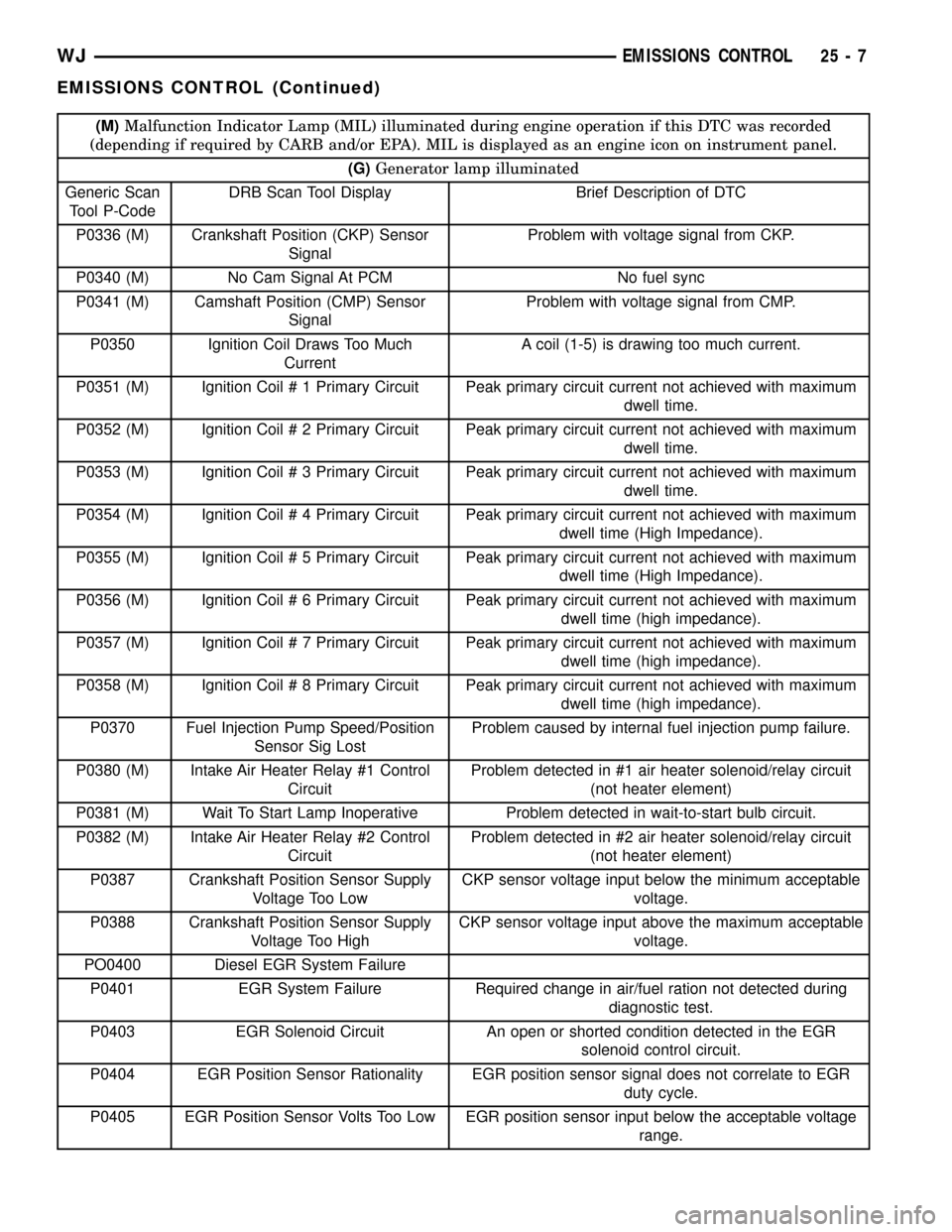
(M)Malfunction Indicator Lamp (MIL) illuminated during engine operation if this DTC was recorded
(depending if required by CARB and/or EPA). MIL is displayed as an engine icon on instrument panel.
(G)Generator lamp illuminated
Generic Scan
Tool P-CodeDRB Scan Tool Display Brief Description of DTC
P0336 (M) Crankshaft Position (CKP) Sensor
SignalProblem with voltage signal from CKP.
P0340 (M) No Cam Signal At PCM No fuel sync
P0341 (M) Camshaft Position (CMP) Sensor
SignalProblem with voltage signal from CMP.
P0350 Ignition Coil Draws Too Much
CurrentA coil (1-5) is drawing too much current.
P0351 (M) Ignition Coil # 1 Primary Circuit Peak primary circuit current not achieved with maximum
dwell time.
P0352 (M) Ignition Coil # 2 Primary Circuit Peak primary circuit current not achieved with maximum
dwell time.
P0353 (M) Ignition Coil # 3 Primary Circuit Peak primary circuit current not achieved with maximum
dwell time.
P0354 (M) Ignition Coil # 4 Primary Circuit Peak primary circuit current not achieved with maximum
dwell time (High Impedance).
P0355 (M) Ignition Coil # 5 Primary Circuit Peak primary circuit current not achieved with maximum
dwell time (High Impedance).
P0356 (M) Ignition Coil # 6 Primary Circuit Peak primary circuit current not achieved with maximum
dwell time (high impedance).
P0357 (M) Ignition Coil # 7 Primary Circuit Peak primary circuit current not achieved with maximum
dwell time (high impedance).
P0358 (M) Ignition Coil # 8 Primary Circuit Peak primary circuit current not achieved with maximum
dwell time (high impedance).
P0370 Fuel Injection Pump Speed/Position
Sensor Sig LostProblem caused by internal fuel injection pump failure.
P0380 (M) Intake Air Heater Relay #1 Control
CircuitProblem detected in #1 air heater solenoid/relay circuit
(not heater element)
P0381 (M) Wait To Start Lamp Inoperative Problem detected in wait-to-start bulb circuit.
P0382 (M) Intake Air Heater Relay #2 Control
CircuitProblem detected in #2 air heater solenoid/relay circuit
(not heater element)
P0387 Crankshaft Position Sensor Supply
Voltage Too LowCKP sensor voltage input below the minimum acceptable
voltage.
P0388 Crankshaft Position Sensor Supply
Voltage Too HighCKP sensor voltage input above the maximum acceptable
voltage.
PO0400 Diesel EGR System Failure
P0401 EGR System Failure Required change in air/fuel ration not detected during
diagnostic test.
P0403 EGR Solenoid Circuit An open or shorted condition detected in the EGR
solenoid control circuit.
P0404 EGR Position Sensor Rationality EGR position sensor signal does not correlate to EGR
duty cycle.
P0405 EGR Position Sensor Volts Too Low EGR position sensor input below the acceptable voltage
range.
WJEMISSIONS CONTROL 25 - 7
EMISSIONS CONTROL (Continued)
Page 2163 of 2199
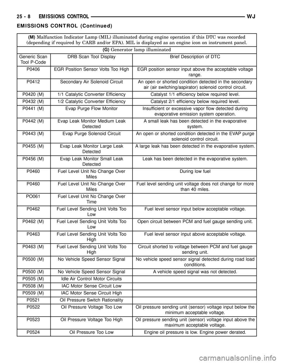
(M)Malfunction Indicator Lamp (MIL) illuminated during engine operation if this DTC was recorded
(depending if required by CARB and/or EPA). MIL is displayed as an engine icon on instrument panel.
(G)Generator lamp illuminated
Generic Scan
Tool P-CodeDRB Scan Tool Display Brief Description of DTC
P0406 EGR Position Sensor Volts Too High EGR position sensor input above the acceptable voltage
range.
P0412 Secondary Air Solenoid Circuit An open or shorted condition detected in the secondary
air (air switching/aspirator) solenoid control circuit.
P0420 (M) 1/1 Catalytic Converter Efficiency Catalyst 1/1 efficiency below required level.
P0432 (M) 1/2 Catalytic Converter Efficiency Catalyst 2/1 efficiency below required level.
P0441 (M) Evap Purge Flow Monitor Insufficient or excessive vapor flow detected during
evaporative emission system operation.
P0442 (M) Evap Leak Monitor Medium Leak
DetectedA small leak has been detected in the evaporative
system.
P0443 (M) Evap Purge Solenoid Circuit An open or shorted condition detected in the EVAP purge
solenoid control circuit.
P0455 (M) Evap Leak Monitor Large Leak
DetectedA large leak has been detected in the evaporative system.
P0456 (M) Evap Leak Monitor Small Leak
DetectedLeak has been detected in the evaporative system.
P0460 Fuel Level Unit No Change Over
MilesDuring low fuel
P0460 Fuel Level Unit No Change Over
MilesFuel level sending unit voltage does not change for more
than 40 miles.
PO061 Fuel Level Unit No Change Over
Time
P0462 Fuel Level Sending Unit Volts Too
LowFuel level sensor input below acceptable voltage.
P0462 (M) Fuel Level Sending Unit Volts Too
LowOpen circuit between PCM and fuel gauge sending unit.
P0463 Fuel Level Sending Unit Volts Too
HighFuel level sensor input above acceptable voltage.
P0463 (M) Fuel Level Sending Unit Volts Too
HighCircuit shorted to voltage between PCM and fuel gauge
sending unit.
P0500 (M) No Vehicle Speed Sensor Signal No vehicle speed sensor signal detected during road load
conditions.
P0500 (M) No Vehicle Speed Sensor Signal A vehicle speed signal was not detected.
P0505 (M) Idle Air Control Motor Circuits
P0508 (M) IAC Motor Sense Circuit Low
P0509 (M) IAC Motor Sense Circuit High
P0521 Oil Pressure Switch Rationality
P0522 Oil Pressure Voltage Too Low Oil pressure sending unit (sensor) voltage input below the
minimum acceptable voltage.
P0523 Oil Pressure Voltage Too High Oil pressure sending unit (sensor) voltage input above the
maximum acceptable voltage.
P0524 Oil Pressure Too Low Engine oil pressure is low. Engine power derated.
25 - 8 EMISSIONS CONTROLWJ
EMISSIONS CONTROL (Continued)
Page 2164 of 2199
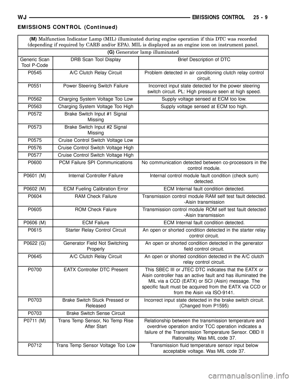
(M)Malfunction Indicator Lamp (MIL) illuminated during engine operation if this DTC was recorded
(depending if required by CARB and/or EPA). MIL is displayed as an engine icon on instrument panel.
(G)Generator lamp illuminated
Generic Scan
Tool P-CodeDRB Scan Tool Display Brief Description of DTC
P0545 A/C Clutch Relay Circuit Problem detected in air conditioning clutch relay control
circuit.
P0551 Power Steering Switch Failure Incorrect input state detected for the power steering
switch circuit. PL: High pressure seen at high speed.
P0562 Charging System Voltage Too Low Supply voltage sensed at ECM too low.
P0563 Charging System Voltage Too High Supply voltage sensed at ECM too high.
P0572 Brake Switch Input #1 Signal
Missing
P0573 Brake Switch Input #2 Signal
Missing
P0575 Cruise Control Switch Voltage Low
P0576 Cruise Control Switch Voltage High
P0577 Cruise Control Switch Voltage High
P0600 PCM Failure SPI Communications No communication detected between co-processors in the
control module.
P0601 (M) Internal Controller Failure Internal control module fault condition (check sum)
detected.
P0602 (M) ECM Fueling Calibration Error ECM Internal fault condition detected.
P0604 RAM Check Failure Transmission control module RAM self test fault detected.
-Aisin transmission
P0605 ROM Check Falure Transmission control module ROM self test fault detected
-Aisin transmission
P0606 (M) ECM Failure ECM Internal fault condition detected.
P0615 Starter Relay Control Circuit An open or shorted condition detected in the starter relay
control circuit.
P0622 (G) Generator Field Not Switching
ProperlyAn open or shorted condition detected in the generator
field control circuit.
P0645 A/C Clutch Relay Circuit An open or shorted condition detected in the A/C clutch
relay control circuit.
P0700 EATX Controller DTC Present This SBEC III or JTEC DTC indicates that the EATX or
Aisin controller has an active fault and has illuminated the
MIL via a CCD (EATX) or SCI (Aisin) message. The
specific fault must be acquired from the EATX via CCD or
from the Aisin via ISO-9141.
P0703 Brake Switch Stuck Pressed or
ReleasedIncorrect input state detected in the brake switch circuit.
(Changed from P1595)
P0703 Brake Switch Sense Circuit
P0711 (M) Trans Temp Sensor, No Temp Rise
After StartRelationship between the transmission temperature and
overdrive operation and/or TCC operation indicates a
failure of the Transmission Temperature Sensor. OBD II
Rationality. Was MIL code 37.
P0712 Trans Temp Sensor Voltage Too Low Transmission fluid temperature sensor input below
acceptable voltage. Was MIL code 37.
WJEMISSIONS CONTROL 25 - 9
EMISSIONS CONTROL (Continued)
Page 2166 of 2199
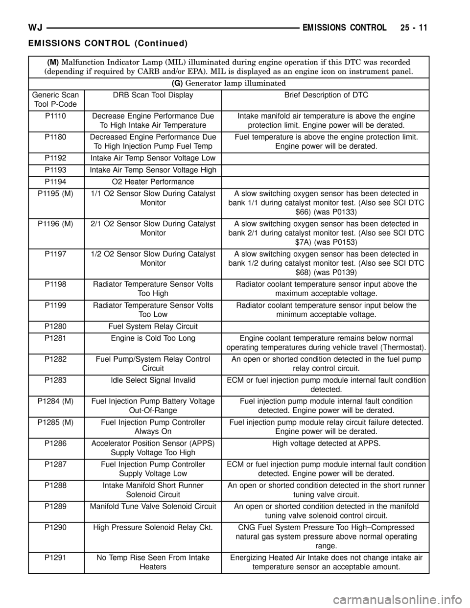
(M)Malfunction Indicator Lamp (MIL) illuminated during engine operation if this DTC was recorded
(depending if required by CARB and/or EPA). MIL is displayed as an engine icon on instrument panel.
(G)Generator lamp illuminated
Generic Scan
Tool P-CodeDRB Scan Tool Display Brief Description of DTC
P1110 Decrease Engine Performance Due
To High Intake Air TemperatureIntake manifold air temperature is above the engine
protection limit. Engine power will be derated.
P1180 Decreased Engine Performance Due
To High Injection Pump Fuel TempFuel temperature is above the engine protection limit.
Engine power will be derated.
P1192 Intake Air Temp Sensor Voltage Low
P1193 Intake Air Temp Sensor Voltage High
P1194 O2 Heater Performance
P1195 (M) 1/1 O2 Sensor Slow During Catalyst
MonitorA slow switching oxygen sensor has been detected in
bank 1/1 during catalyst monitor test. (Also see SCI DTC
$66) (was P0133)
P1196 (M) 2/1 O2 Sensor Slow During Catalyst
MonitorA slow switching oxygen sensor has been detected in
bank 2/1 during catalyst monitor test. (Also see SCI DTC
$7A) (was P0153)
P1197 1/2 O2 Sensor Slow During Catalyst
MonitorA slow switching oxygen sensor has been detected in
bank 1/2 during catalyst monitor test. (Also see SCI DTC
$68) (was P0139)
P1198 Radiator Temperature Sensor Volts
Too HighRadiator coolant temperature sensor input above the
maximum acceptable voltage.
P1199 Radiator Temperature Sensor Volts
Too LowRadiator coolant temperature sensor input below the
minimum acceptable voltage.
P1280 Fuel System Relay Circuit
P1281 Engine is Cold Too Long Engine coolant temperature remains below normal
operating temperatures during vehicle travel (Thermostat).
P1282 Fuel Pump/System Relay Control
CircuitAn open or shorted condition detected in the fuel pump
relay control circuit.
P1283 Idle Select Signal Invalid ECM or fuel injection pump module internal fault condition
detected.
P1284 (M) Fuel Injection Pump Battery Voltage
Out-Of-RangeFuel injection pump module internal fault condition
detected. Engine power will be derated.
P1285 (M) Fuel Injection Pump Controller
Always OnFuel injection pump module relay circuit failure detected.
Engine power will be derated.
P1286 Accelerator Position Sensor (APPS)
Supply Voltage Too HighHigh voltage detected at APPS.
P1287 Fuel Injection Pump Controller
Supply Voltage LowECM or fuel injection pump module internal fault condition
detected. Engine power will be derated.
P1288 Intake Manifold Short Runner
Solenoid CircuitAn open or shorted condition detected in the short runner
tuning valve circuit.
P1289 Manifold Tune Valve Solenoid Circuit An open or shorted condition detected in the manifold
tuning valve solenoid control circuit.
P1290 High Pressure Solenoid Relay Ckt. CNG Fuel System Pressure Too High±Compressed
natural gas system pressure above normal operating
range.
P1291 No Temp Rise Seen From Intake
HeatersEnergizing Heated Air Intake does not change intake air
temperature sensor an acceptable amount.
WJEMISSIONS CONTROL 25 - 11
EMISSIONS CONTROL (Continued)
Page 2167 of 2199
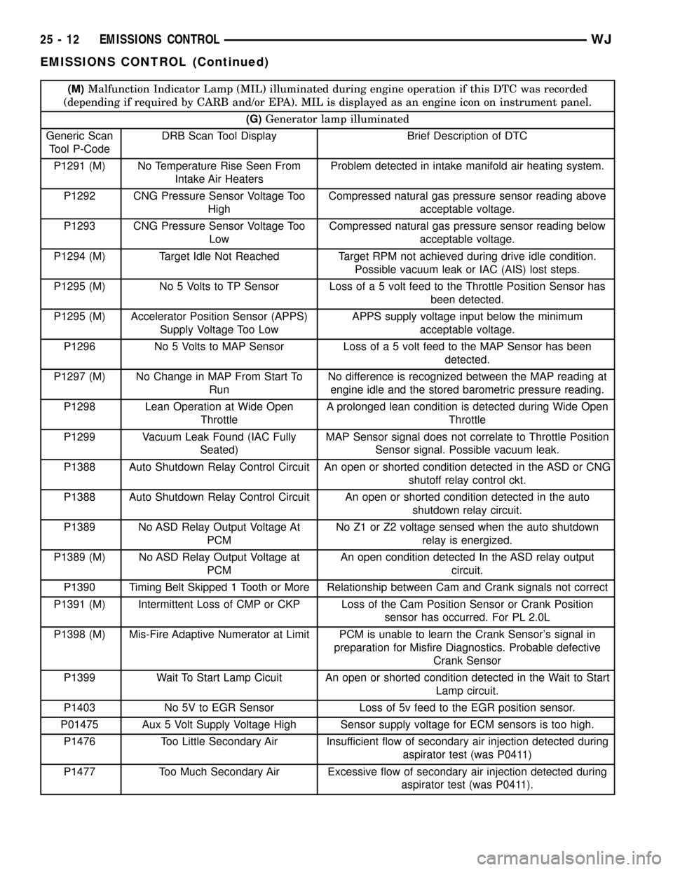
(M)Malfunction Indicator Lamp (MIL) illuminated during engine operation if this DTC was recorded
(depending if required by CARB and/or EPA). MIL is displayed as an engine icon on instrument panel.
(G)Generator lamp illuminated
Generic Scan
Tool P-CodeDRB Scan Tool Display Brief Description of DTC
P1291 (M) No Temperature Rise Seen From
Intake Air HeatersProblem detected in intake manifold air heating system.
P1292 CNG Pressure Sensor Voltage Too
HighCompressed natural gas pressure sensor reading above
acceptable voltage.
P1293 CNG Pressure Sensor Voltage Too
LowCompressed natural gas pressure sensor reading below
acceptable voltage.
P1294 (M) Target Idle Not Reached Target RPM not achieved during drive idle condition.
Possible vacuum leak or IAC (AIS) lost steps.
P1295 (M) No 5 Volts to TP Sensor Loss of a 5 volt feed to the Throttle Position Sensor has
been detected.
P1295 (M) Accelerator Position Sensor (APPS)
Supply Voltage Too LowAPPS supply voltage input below the minimum
acceptable voltage.
P1296 No 5 Volts to MAP Sensor Loss of a 5 volt feed to the MAP Sensor has been
detected.
P1297 (M) No Change in MAP From Start To
RunNo difference is recognized between the MAP reading at
engine idle and the stored barometric pressure reading.
P1298 Lean Operation at Wide Open
ThrottleA prolonged lean condition is detected during Wide Open
Throttle
P1299 Vacuum Leak Found (IAC Fully
Seated)MAP Sensor signal does not correlate to Throttle Position
Sensor signal. Possible vacuum leak.
P1388 Auto Shutdown Relay Control Circuit An open or shorted condition detected in the ASD or CNG
shutoff relay control ckt.
P1388 Auto Shutdown Relay Control Circuit An open or shorted condition detected in the auto
shutdown relay circuit.
P1389 No ASD Relay Output Voltage At
PCMNo Z1 or Z2 voltage sensed when the auto shutdown
relay is energized.
P1389 (M) No ASD Relay Output Voltage at
PCMAn open condition detected In the ASD relay output
circuit.
P1390 Timing Belt Skipped 1 Tooth or More Relationship between Cam and Crank signals not correct
P1391 (M) Intermittent Loss of CMP or CKP Loss of the Cam Position Sensor or Crank Position
sensor has occurred. For PL 2.0L
P1398 (M) Mis-Fire Adaptive Numerator at Limit PCM is unable to learn the Crank Sensor's signal in
preparation for Misfire Diagnostics. Probable defective
Crank Sensor
P1399 Wait To Start Lamp Cicuit An open or shorted condition detected in the Wait to Start
Lamp circuit.
P1403 No 5V to EGR Sensor Loss of 5v feed to the EGR position sensor.
P01475 Aux 5 Volt Supply Voltage High Sensor supply voltage for ECM sensors is too high.
P1476 Too Little Secondary Air Insufficient flow of secondary air injection detected during
aspirator test (was P0411)
P1477 Too Much Secondary Air Excessive flow of secondary air injection detected during
aspirator test (was P0411).
25 - 12 EMISSIONS CONTROLWJ
EMISSIONS CONTROL (Continued)
Page 2168 of 2199
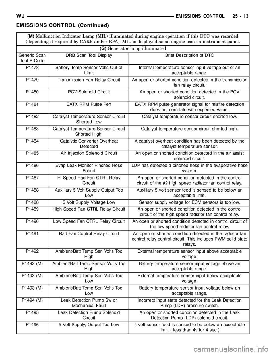
(M)Malfunction Indicator Lamp (MIL) illuminated during engine operation if this DTC was recorded
(depending if required by CARB and/or EPA). MIL is displayed as an engine icon on instrument panel.
(G)Generator lamp illuminated
Generic Scan
Tool P-CodeDRB Scan Tool Display Brief Description of DTC
P1478 Battery Temp Sensor Volts Out of
LimitInternal temperature sensor input voltage out of an
acceptable range.
P1479 Transmission Fan Relay Circuit An open or shorted condition detected in the transmission
fan relay circuit.
P1480 PCV Solenoid Circuit An open or shorted condition detected in the PCV
solenoid circuit.
P1481 EATX RPM Pulse Perf EATX RPM pulse generator signal for misfire detection
does not correlate with expected value.
P1482 Catalyst Temperature Sensor Circuit
Shorted LowCatalyst temperature sensor circuit shorted low.
P1483 Catalyst Temperature Sensor Circuit
Shorted High.Catalyst temperature sensor circuit shorted high.
P1484 Catalytic Converter Overheat
DetectedA catalyst overheat condition has been detected by the
catalyst temperature sensor.
P1485 Air Injection Solenoid Circuit An open or shorted condition detected in the air assist
solenoid circuit.
P1486 Evap Leak Monitor Pinched Hose
FoundLDP has detected a pinched hose in the evaporative hose
system.
P1487 Hi Speed Rad Fan CTRL Relay
CircuitAn open or shorted condition detected in the control
circuit of the #2 high speed radiator fan control relay.
P1488 Auxiliary 5 Volt Supply Output Too
LowAuxiliary 5 volt sensor feed is sensed to be below an
acceptable limit.
P1488 5 Volt Supply Voltage Low Sensor supply voltage for ECM sensors is too low.
P1489 High Speed Fan CTRL Relay Circuit An open or shorted condition detected in the control
circuit of the high speed radiator fan control relay.
P1490 Low Speed Fan CTRL Relay Circuit An open or shorted condition detected in control circuit of
the low speed radiator fan control relay.
P1491 Rad Fan Control Relay Circuit An open or shorted condition detected in the radiator fan
control relay control circuit. This includes PWM solid state
relays.
P1492 Ambient/Batt Temp Sen Volts Too
HighExternal temperature sensor input above acceptable
voltage.
P1492 (M) Ambient/Batt Temp Sensor Volts Too
HighBattery temperature sensor input voltage above an
acceptable range.
P1493 (M) Ambient/Batt Temp Sen Volts Too
LowExternal temperature sensor input below acceptable
voltage.
P1493 (M) Ambient/Batt Temp Sen Volts Too
LowBattery temperature sensor input voltage below an
acceptable range.
P1494 (M) Leak Detection Pump Sw or
Mechanical FaultIncorrect input state detected for the Leak Detection
Pump (LDP) pressure switch.
P1495 Leak Detection Pump Solenoid
CircuitAn open or shorted condition detected in the Leak
Detection Pump (LDP) solenoid circuit.
P1496 5 Volt Supply, Output Too Low 5 volt sensor feed is sensed to be below an acceptable
limit. ( less than 4v for 4 sec )
WJEMISSIONS CONTROL 25 - 13
EMISSIONS CONTROL (Continued)
Page 2170 of 2199
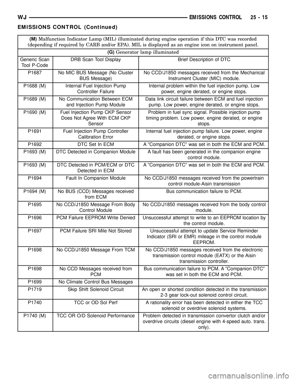
(M)Malfunction Indicator Lamp (MIL) illuminated during engine operation if this DTC was recorded
(depending if required by CARB and/or EPA). MIL is displayed as an engine icon on instrument panel.
(G)Generator lamp illuminated
Generic Scan
Tool P-CodeDRB Scan Tool Display Brief Description of DTC
P1687 No MIC BUS Message (No Cluster
BUS Message)No CCD/J1850 messages received from the Mechanical
Instrument Cluster (MIC) module.
P1688 (M) Internal Fuel Injection Pump
Controller FailureInternal problem within the fuel injection pump. Low
power, engine derated, or engine stops.
P1689 (M) No Communication Between ECM
and Injection Pump ModuleData link circuit failure between ECM and fuel injection
pump. Low power, engine derated, or engine stops.
P1690 (M) Fuel Injection Pump CKP Sensor
Does Not Agree With ECM CKP
SensorProblem in fuel sync signal. Possible injection pump
timing problem. Low power, engine derated, or engine
stops.
P1691 Fuel Injection Pump Controller
Calibration ErrorInternal fuel injection pump failure. Low power, engine
derated, or engine stops.
P1692 DTC Set In ECM A9Companion DTC9was set in both the ECM and PCM.
P1693 (M) DTC Detected in Companion Module A fault has been generated in the companion engine
control module.
P1693 (M) DTC Detected in PCM/ECM or DTC
Detected in ECMA9Companion DTC9was set in both the ECM and PCM.
P1694 Fault In Companion Module No CCD/J1850 messages received from the powertrain
control module-Aisin transmission
P1694 (M) No BUS (CCD) Messages received
from ECMBus communication failure to PCM.
P1695 No CCD/J1850 Message From Body
Control ModuleNo CCD/J1850 messages received from the body control
module.
P1696 PCM Failure EEPROM Write Denied Unsuccessful attempt to write to an EEPROM location by
the control module.
P1697 PCM Failure SRI Mile Not Stored Unsuccessful attempt to update Service Reminder
Indicator (SRI or EMR) mileage in the control module
EEPROM.
P1698 No CCD/J1850 Message From TCM No CCD/J1850 messages received from the electronic
transmission control module (EATX) or the Aisin
transmission controller.
P1698 No CCD Messages received from
PCMBus communication failure to PCM. A9Companion DTC9
was set in both the ECM and PCM.
P1699 No Climate Control Bus Messages
P1719 Skip Shift Solenoid Circuit An open or shorted condition detected in the transmission
2-3 gear lock-out solenoid control circuit.
P1740 TCC or OD Sol Perf A rationality error has been detected in either the TCC
solenoid or overdrive solenoid systems.
P1740 (M) TCC OR O/D Solenoid Performance Problem detected in transmission convertor clutch and/or
overdrive circuits (diesel engine with 4-speed auto. trans.
only).
WJEMISSIONS CONTROL 25 - 15
EMISSIONS CONTROL (Continued)
Page 2175 of 2199

an associated limp in will take two trips to illumi-
nate the MIL.
Refer to the Diagnostic Trouble Codes Description
Charts in this section and the appropriate Power-
train Diagnostic Procedure Manual for diagnostic
procedures.
DESCRIPTION - NON-MONITORED CIRCUITS
The PCM does not monitor the following circuits,
systems and conditions that could have malfunctions
causing driveability problems. The PCM might not
store diagnostic trouble codes for these conditions.
However, problems with these systems may cause the
PCM to store diagnostic trouble codes for other sys-
tems or components. For example, a fuel pressure
problem will not register a fault directly, but could
cause a rich/lean condition or misfire. This could
cause the PCM to store an oxygen sensor or misfire
diagnostic trouble code
FUEL PRESSURE
The fuel pressure regulator controls fuel system
pressure. The PCM cannot detect a clogged fuel
pump inlet filter, clogged in-line fuel filter, or a
pinched fuel supply or return line. However, these
could result in a rich or lean condition causing the
PCM to store an oxygen sensor or fuel system diag-
nostic trouble code.
SECONDARY IGNITION CIRCUIT
The PCM cannot detect an inoperative ignition coil,
fouled or worn spark plugs, ignition cross firing, or
open spark plug cables.
CYLINDER COMPRESSION
The PCM cannot detect uneven, low, or high engine
cylinder compression.
EXHAUST SYSTEM
The PCM cannot detect a plugged, restricted or
leaking exhaust system, although it may set a fuel
system fault.
FUEL INJECTOR MECHANICAL MALFUNCTIONS
The PCM cannot determine if a fuel injector is
clogged, the needle is sticking or if the wrong injectoris installed. However, these could result in a rich or
lean condition causing the PCM to store a diagnostic
trouble code for either misfire, an oxygen sensor, or
the fuel system.
EXCESSIVE OIL CONSUMPTION
Although the PCM monitors engine exhaust oxygen
content when the system is in closed loop, it cannot
determine excessive oil consumption.
THROTTLE BODY AIRFLOW
The PCM cannot detect a clogged or restricted air
cleaner inlet or filter element.
VACUUM ASSIST
The PCM cannot detect leaks or restrictions in the
vacuum circuits of vacuum assisted engine control
system devices. However, these could cause the PCM
to store a MAP sensor diagnostic trouble code and
cause a high idle condition.
PCM SYSTEM GROUND
The PCM cannot determine a poor system ground.
However, one or more diagnostic trouble codes may
be generated as a result of this condition. The mod-
ule should be mounted to the body at all times, also
during diagnostic.
PCM CONNECTOR ENGAGEMENT
The PCM may not be able to determine spread or
damaged connector pins. However, it might store
diagnostic trouble codes as a result of spread connec-
tor pins.
DESCRIPTION - HIGH AND LOW LIMITS
The PCM compares input signal voltages from each
input device with established high and low limits for
the device. If the input voltage is not within limits
and other criteria are met, the PCM stores a diagnos-
tic trouble code in memory. Other diagnostic trouble
code criteria might include engine RPM limits or
input voltages from other sensors or switches that
must be present before verifying a diagnostic trouble
code condition.
DESCRIPTION - LOAD VALUE
ENGINE IDLE/NEUTRAL 2500 RPM/NEUTRAL
All Engines 2% to 8% of Maximum Load 9% to 17% of Maximum Load
25 - 20 EMISSIONS CONTROLWJ
EMISSIONS CONTROL (Continued)
Page 2186 of 2199

OPERATION
The main purpose of the LDP is to pressurize the
fuel system for leak checking. It closes the EVAP sys-
tem vent to atmospheric pressure so the system can
be pressurized for leak testing. The diaphragm is
powered by engine vacuum. It pumps air into the
EVAP system to develop a pressure of about 7.59
H2O (1/4) psi. A reed switch in the LDP allows the
PCM to monitor the position of the LDP diaphragm.
The PCM uses the reed switch input to monitor how
fast the LDP is pumping air into the EVAP system.
This allows detection of leaks and blockage. The LDP
assembly consists of several parts (Fig. 12). The sole-
noid is controlled by the PCM, and it connects the
upper pump cavity to either engine vacuum or atmo-
spheric pressure. A vent valve closes the EVAP sys-
tem to atmosphere, sealing the system during leak
testing. The pump section of the LDP consists of a
diaphragm that moves up and down to bring air in
through the air filter and inlet check valve, and
pump it out through an outlet check valve into the
EVAP system. The diaphragm is pulled up by engine
vacuum, and pushed down by spring pressure, as the
LDP solenoid turns on and off. The LDP also has a
magnetic reed switch to signal diaphragm position to
the PCM. When the diaphragm is down, the switch is
closed, which sends a 12 V (system voltage) signal to
the PCM. When the diaphragm is up, the switch is
open, and there is no voltage sent to the PCM. This
allows the PCM to monitor LDP pumping action as it
turns the LDP solenoid on and off.
LDP AT REST (NOT POWERED)
When the LDP is at rest (no electrical/vacuum) the
diaphragm is allowed to drop down if the internal
(EVAP system) pressure is not greater than the
return spring. The LDP solenoid blocks the engine
vacuum port and opens the atmospheric pressure
port connected through the EVAP system air filter.
The vent valve is held open by the diaphragm. This
allows the canister to see atmospheric pressure (Fig.
13).
DIAPHRAGM UPWARD MOVEMENT
When the PCM energizes the LDP solenoid, the
solenoid blocks the atmospheric port leading through
the EVAP air filter and at the same time opens the
engine vacuum port to the pump cavity above the
diaphragm. The diaphragm moves upward when vac-
uum above the diaphragm exceeds spring force. This
upward movement closes the vent valve. It also
causes low pressure below the diaphragm, unseating
the inlet check valve and allowing air in from the
EVAP air filter. When the diaphragm completes its
upward movement, the LDP reed switch turns from
closed to open (Fig. 14).
DIAPHRAGM DOWNWARD MOVEMENT
Based on reed switch input, the PCM de-energizes
the LDP solenoid, causing it to block the vacuum
port, and open the atmospheric port. This connects
the upper pump cavity to atmosphere through the
EVAP air filter. The spring is now able to push the
diaphragm down. The downward movement of the
diaphragm closes the inlet check valve and opens the
outlet check valve pumping air into the evaporative
system. The LDP reed switch turns from open to
closed, allowing the PCM to monitor LDP pumping
(diaphragm up/down) activity (Fig. 15). During the
pumping mode, the diaphragm will not move down
far enough to open the vent valve. The pumping cycle
is repeated as the solenoid is turned on and off.
When the evaporative system begins to pressurize,
the pressure on the bottom of the diaphragm will
begin to oppose the spring pressure, slowing the
pumping action. The PCM watches the time from
when the solenoid is de-energized, until the dia-
phragm drops down far enough for the reed switch to
Fig. 12 EVAP LEAK DETECTION SYSTEM
COMPONENTS
1 - Reed Switch
2 - Solenoid
3 - Spring
4 - Pump Cavity
5 - Diaphragm
6 - Inlet Check Valve
7 - Vent Valve
8 - From Air Filter
9 - To Canister
10 - Outlet Check Valve
11 - Engine Vacuum
WJEVAPORATIVE EMISSIONS 25 - 31
LEAK DETECTION PUMP (Continued)