JEEP GRAND CHEROKEE 2002 WJ / 2.G Workshop Manual
Manufacturer: JEEP, Model Year: 2002, Model line: GRAND CHEROKEE, Model: JEEP GRAND CHEROKEE 2002 WJ / 2.GPages: 2199, PDF Size: 76.01 MB
Page 1891 of 2199
WINDOW REGULATOR
REMOVAL
(1) Remove front door glass, refer to (Refer to 23 -
BODY/DOOR - FRONT/DOOR GLASS - REMOVAL).
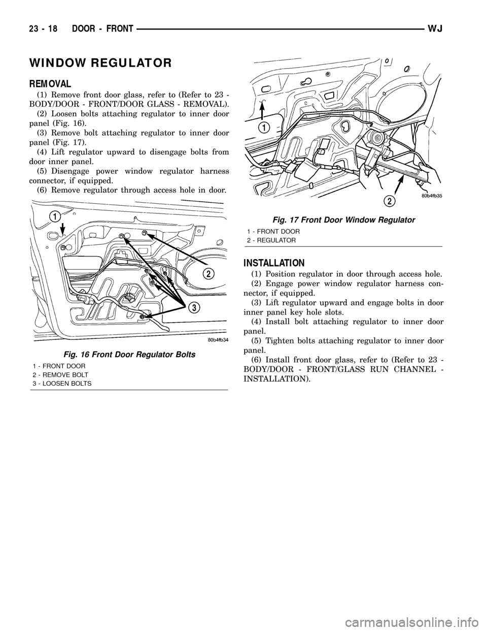
(2) Loosen bolts attaching regulator to inner door
panel (Fig. 16).
(3) Remove bolt attaching regulator to inner door
panel (Fig. 17).
(4) Lift regulator upward to disengage bolts from
door inner panel.
(5) Disengage power window regulator harness
connector, if equipped.
(6) Remove regulator through access hole in door.
INSTALLATION
(1) Position regulator in door through access hole.
(2) Engage power window regulator harness con-
nector, if equipped.
(3) Lift regulator upward and engage bolts in door
inner panel key hole slots.
(4) Install bolt attaching regulator to inner door
panel.
(5) Tighten bolts attaching regulator to inner door
panel.
(6) Install front door glass, refer to (Refer to 23 -
BODY/DOOR - FRONT/GLASS RUN CHANNEL -
INSTALLATION).
Fig. 16 Front Door Regulator Bolts
1 - FRONT DOOR
2 - REMOVE BOLT
3 - LOOSEN BOLTS
Fig. 17 Front Door Window Regulator
1 - FRONT DOOR
2 - REGULATOR
23 - 18 DOOR - FRONTWJ
Page 1892 of 2199

DOORS - REAR
TABLE OF CONTENTS
page page
CHECK STRAP
REMOVAL.............................19
INSTALLATION.........................19
DOOR
REMOVAL.............................20
INSTALLATION.........................20
DOOR GLASS
REMOVAL.............................20
INSTALLATION.........................20
EXTERIOR HANDLE
REMOVAL.............................20
INSTALLATION.........................21
HINGE
REMOVAL.............................21
INSTALLATION.........................21
INSIDE HANDLE ACTUATOR
REMOVAL.............................22INSTALLATION.........................22
LATCH
REMOVAL.............................22
INSTALLATION.........................22
LATCH STRIKER
REMOVAL.............................23
INSTALLATION.........................23
TRIM PANEL
REMOVAL.............................23
INSTALLATION.........................23
WATERDAM
REMOVAL.............................23
INSTALLATION.........................24
WINDOW REGULATOR
REMOVAL.............................24
INSTALLATION.........................24
CHECK STRAP
REMOVAL
(1) Remove waterdam, refer to (Refer to 23 -
BODY/DOORS - REAR/WATERDAM - REMOVAL).
(2) Remove speaker.
(3) Remove screws attaching door check to B-pillar.
(4) Remove nuts attaching door check to door (Fig.
1).
(5) Remove door check through speaker location
hole.
INSTALLATION
(1) Position door check on door through speaker
location hole.
(2) Install nuts attaching door check to door (Fig.
1).
(3) Install screws attaching door check to B-pillar.
(4) Install speaker.
(5) Install waterdam, refer to (Refer to 23 - BODY/
DOORS - REAR/WATERDAM - INSTALLATION).
Fig. 1 Door Check
1 - DOOR CHECK
2 - REAR DOOR
WJDOORS - REAR 23 - 19
Page 1893 of 2199
DOOR
REMOVAL
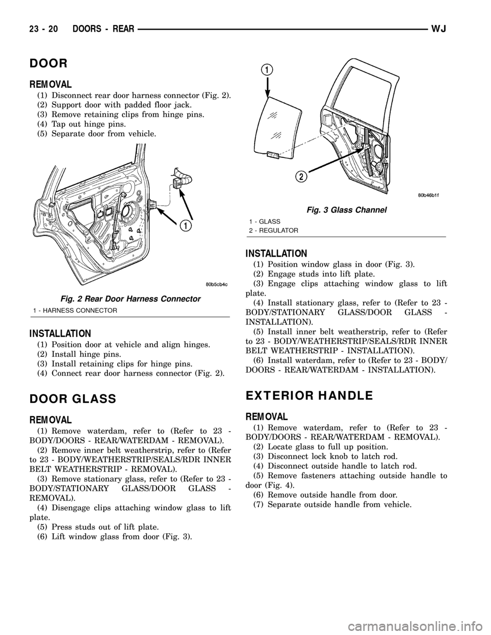
(1) Disconnect rear door harness connector (Fig. 2).
(2) Support door with padded floor jack.
(3) Remove retaining clips from hinge pins.
(4) Tap out hinge pins.
(5) Separate door from vehicle.
INSTALLATION
(1) Position door at vehicle and align hinges.
(2) Install hinge pins.
(3) Install retaining clips for hinge pins.
(4) Connect rear door harness connector (Fig. 2).
DOOR GLASS
REMOVAL
(1) Remove waterdam, refer to (Refer to 23 -
BODY/DOORS - REAR/WATERDAM - REMOVAL).
(2) Remove inner belt weatherstrip, refer to (Refer
to 23 - BODY/WEATHERSTRIP/SEALS/RDR INNER
BELT WEATHERSTRIP - REMOVAL).
(3) Remove stationary glass, refer to (Refer to 23 -
BODY/STATIONARY GLASS/DOOR GLASS -
REMOVAL).
(4) Disengage clips attaching window glass to lift
plate.
(5) Press studs out of lift plate.
(6) Lift window glass from door (Fig. 3).
INSTALLATION
(1) Position window glass in door (Fig. 3).
(2) Engage studs into lift plate.
(3) Engage clips attaching window glass to lift
plate.
(4) Install stationary glass, refer to (Refer to 23 -
BODY/STATIONARY GLASS/DOOR GLASS -
INSTALLATION).
(5) Install inner belt weatherstrip, refer to (Refer
to 23 - BODY/WEATHERSTRIP/SEALS/RDR INNER
BELT WEATHERSTRIP - INSTALLATION).
(6) Install waterdam, refer to (Refer to 23 - BODY/
DOORS - REAR/WATERDAM - INSTALLATION).
EXTERIOR HANDLE
REMOVAL
(1) Remove waterdam, refer to (Refer to 23 -
BODY/DOORS - REAR/WATERDAM - REMOVAL).
(2) Locate glass to full up position.
(3) Disconnect lock knob to latch rod.
(4) Disconnect outside handle to latch rod.
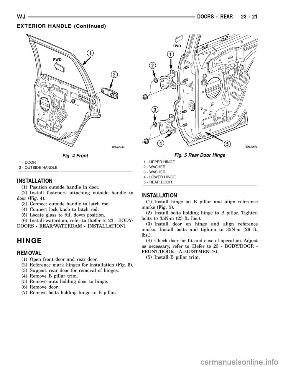
(5) Remove fasteners attaching outside handle to
door (Fig. 4).
(6) Remove outside handle from door.
(7) Separate outside handle from vehicle.
Fig. 2 Rear Door Harness Connector
1 - HARNESS CONNECTOR
Fig. 3 Glass Channel
1 - GLASS
2 - REGULATOR
23 - 20 DOORS - REARWJ
Page 1894 of 2199
INSTALLATION
(1) Position outside handle in door.
(2) Install fasteners attaching outside handle to
door (Fig. 4).
(3) Connect outside handle to latch rod.
(4) Connect lock knob to latch rod.
(5) Locate glass to full down position.
(6) Install waterdam, refer to (Refer to 23 - BODY/
DOORS - REAR/WATERDAM - INSTALLATION).
HINGE
REMOVAL
(1) Open front door and rear door.
(2) Reference mark hinges for installation (Fig. 5).
(3) Support rear door for removal of hinges.
(4) Remove B pillar trim.
(5) Remove nuts holding door to hinge.
(6) Remove door.
(7) Remove bolts holding hinge to B pillar.
INSTALLATION
(1) Install hinge on B pillar and align reference
marks (Fig. 5).
(2) Install bolts holding hinge to B pillar. Tighten
bolts to 35N´m (23 ft. lbs.).
(3) Install door on hinge and align reference
marks. Install bolts and tighten to 35N´m (26 ft.
lbs.).
(4) Check door for fit and ease of operation. Adjust
as necessary, refer to (Refer to 23 - BODY/DOOR -
FRONT/DOOR - ADJUSTMENTS).
(5) Install B pillar trim.
Fig. 4 Front
1 - DOOR
2 - OUTSIDE HANDLE
Fig. 5 Rear Door Hinge
1 - UPPER HINGE
2 - WASHER
3 - WASHER
4 - LOWER HINGE
5 - REAR DOOR
WJDOORS - REAR 23 - 21
EXTERIOR HANDLE (Continued)
Page 1895 of 2199
INSIDE HANDLE ACTUATOR
REMOVAL
(1) Remove door trim panel, refer to (Refer to 23 -
BODY/DOORS - REAR/TRIM PANEL - REMOVAL).
(2) Disconnect latch and lock rods from inside han-
dle actuator.
(3) Remove screws attaching inside handle actua-
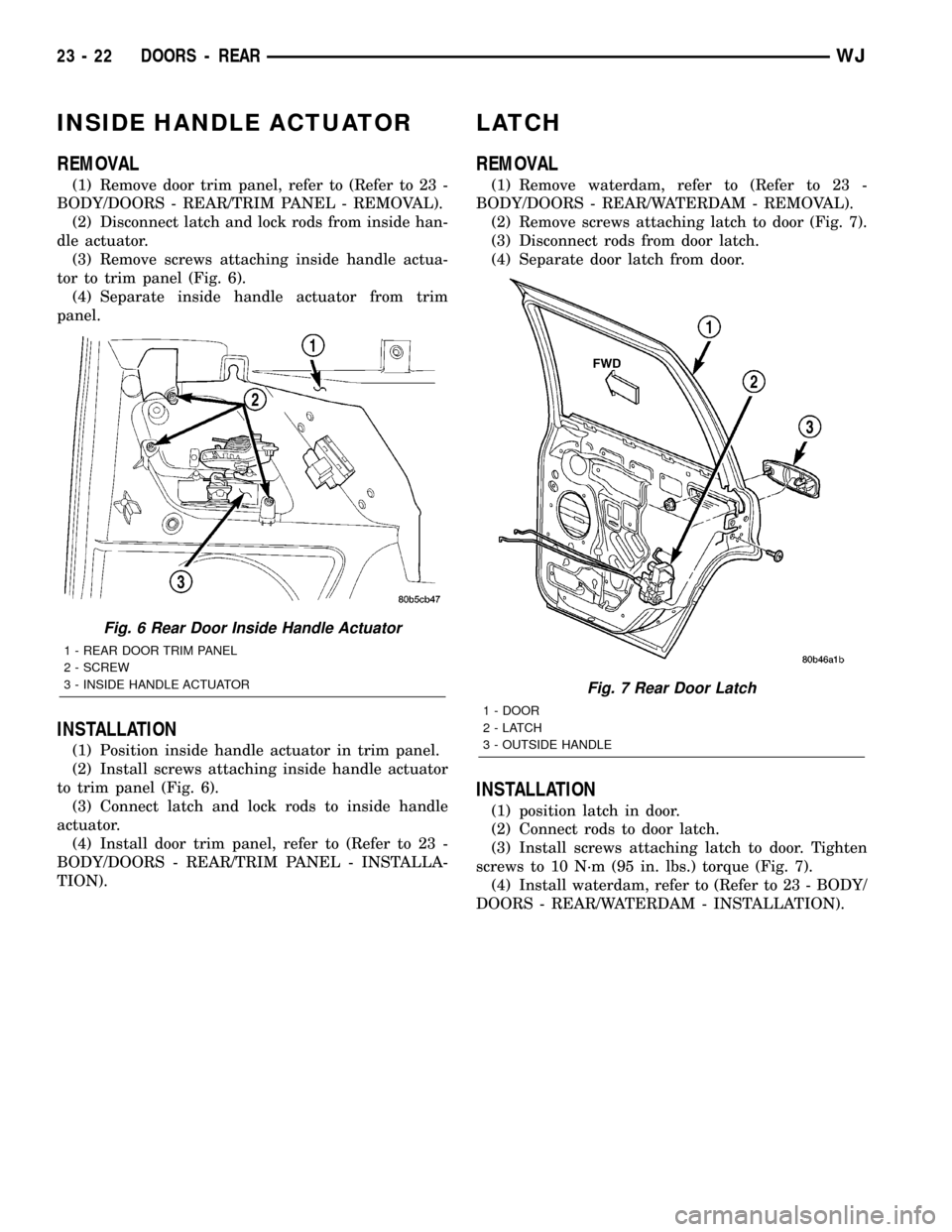
tor to trim panel (Fig. 6).
(4) Separate inside handle actuator from trim
panel.
INSTALLATION
(1) Position inside handle actuator in trim panel.
(2) Install screws attaching inside handle actuator
to trim panel (Fig. 6).
(3) Connect latch and lock rods to inside handle
actuator.
(4) Install door trim panel, refer to (Refer to 23 -
BODY/DOORS - REAR/TRIM PANEL - INSTALLA-
TION).
LATCH
REMOVAL
(1) Remove waterdam, refer to (Refer to 23 -
BODY/DOORS - REAR/WATERDAM - REMOVAL).
(2) Remove screws attaching latch to door (Fig. 7).
(3) Disconnect rods from door latch.
(4) Separate door latch from door.
INSTALLATION
(1) position latch in door.
(2) Connect rods to door latch.
(3) Install screws attaching latch to door. Tighten
screws to 10 N´m (95 in. lbs.) torque (Fig. 7).
(4) Install waterdam, refer to (Refer to 23 - BODY/
DOORS - REAR/WATERDAM - INSTALLATION).
Fig. 6 Rear Door Inside Handle Actuator
1 - REAR DOOR TRIM PANEL
2 - SCREW
3 - INSIDE HANDLE ACTUATOR
Fig. 7 Rear Door Latch
1 - DOOR
2-LATCH
3 - OUTSIDE HANDLE
23 - 22 DOORS - REARWJ
Page 1896 of 2199
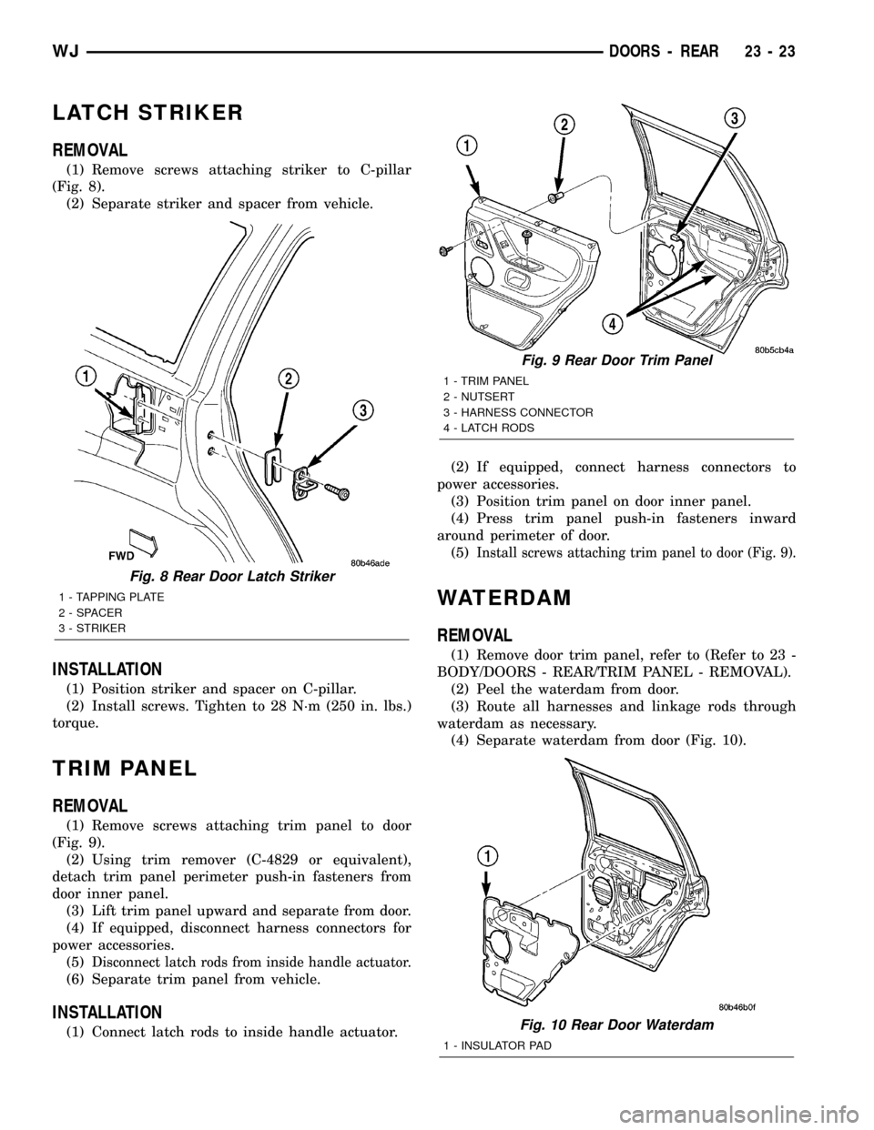
LATCH STRIKER
REMOVAL
(1) Remove screws attaching striker to C-pillar
(Fig. 8).
(2) Separate striker and spacer from vehicle.
INSTALLATION
(1) Position striker and spacer on C-pillar.
(2) Install screws. Tighten to 28 N´m (250 in. lbs.)
torque.
TRIM PANEL
REMOVAL
(1) Remove screws attaching trim panel to door
(Fig. 9).
(2) Using trim remover (C-4829 or equivalent),
detach trim panel perimeter push-in fasteners from
door inner panel.
(3) Lift trim panel upward and separate from door.
(4) If equipped, disconnect harness connectors for
power accessories.
(5)
Disconnect latch rods from inside handle actuator.
(6) Separate trim panel from vehicle.
INSTALLATION
(1) Connect latch rods to inside handle actuator.(2) If equipped, connect harness connectors to
power accessories.
(3) Position trim panel on door inner panel.
(4) Press trim panel push-in fasteners inward
around perimeter of door.
(5)
Install screws attaching trim panel to door (Fig. 9).
WATERDAM
REMOVAL
(1) Remove door trim panel, refer to (Refer to 23 -
BODY/DOORS - REAR/TRIM PANEL - REMOVAL).
(2) Peel the waterdam from door.
(3) Route all harnesses and linkage rods through
waterdam as necessary.
(4) Separate waterdam from door (Fig. 10).
Fig. 8 Rear Door Latch Striker
1 - TAPPING PLATE
2 - SPACER
3 - STRIKER
Fig. 9 Rear Door Trim Panel
1 - TRIM PANEL
2 - NUTSERT
3 - HARNESS CONNECTOR
4 - LATCH RODS
Fig. 10 Rear Door Waterdam
1 - INSULATOR PAD
WJDOORS - REAR 23 - 23
Page 1897 of 2199
INSTALLATION
(1) Waterdam contact surface must be free of con-
taminants. Clean as necessary.
(2) Route all harnesses and linkage rods through
waterdam as necessary.
(3) Position waterdam on door and align all holes
(Fig. 10).
(4) Press waterdam on door.
(5) Install door trim panel, refer to (Refer to 23 -
BODY/DOORS - REAR/TRIM PANEL - INSTALLA-
TION).
WINDOW REGULATOR
REMOVAL
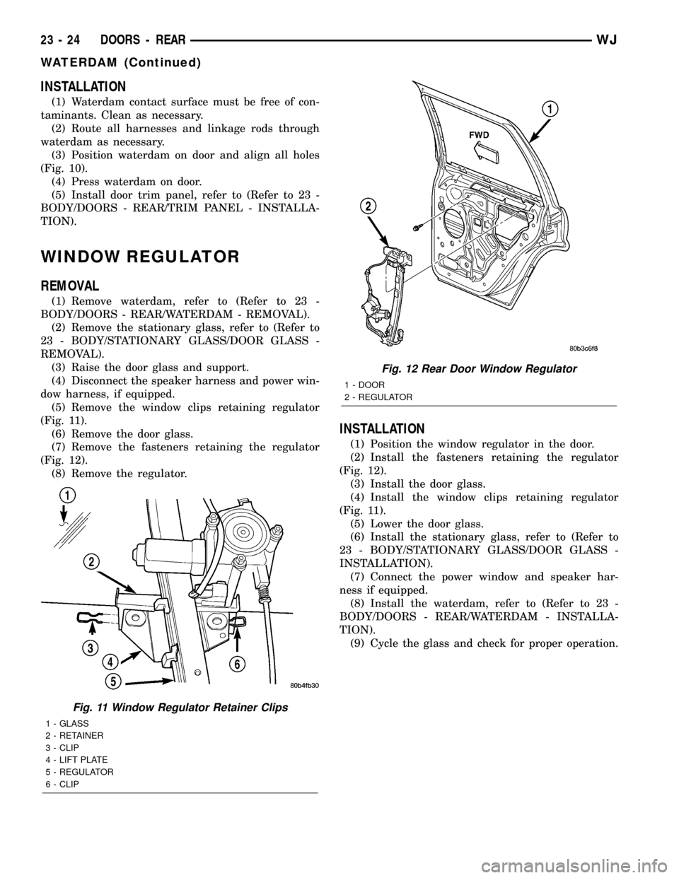
(1) Remove waterdam, refer to (Refer to 23 -
BODY/DOORS - REAR/WATERDAM - REMOVAL).
(2) Remove the stationary glass, refer to (Refer to
23 - BODY/STATIONARY GLASS/DOOR GLASS -
REMOVAL).
(3) Raise the door glass and support.
(4) Disconnect the speaker harness and power win-
dow harness, if equipped.
(5) Remove the window clips retaining regulator
(Fig. 11).
(6) Remove the door glass.
(7) Remove the fasteners retaining the regulator
(Fig. 12).
(8) Remove the regulator.
INSTALLATION
(1) Position the window regulator in the door.
(2) Install the fasteners retaining the regulator
(Fig. 12).
(3) Install the door glass.
(4) Install the window clips retaining regulator
(Fig. 11).
(5) Lower the door glass.
(6) Install the stationary glass, refer to (Refer to
23 - BODY/STATIONARY GLASS/DOOR GLASS -
INSTALLATION).
(7) Connect the power window and speaker har-
ness if equipped.
(8) Install the waterdam, refer to (Refer to 23 -
BODY/DOORS - REAR/WATERDAM - INSTALLA-
TION).
(9) Cycle the glass and check for proper operation.
Fig. 11 Window Regulator Retainer Clips
1 - GLASS
2 - RETAINER
3 - CLIP
4 - LIFT PLATE
5 - REGULATOR
6 - CLIP
Fig. 12 Rear Door Window Regulator
1 - DOOR
2 - REGULATOR
23 - 24 DOORS - REARWJ
WATERDAM (Continued)
Page 1898 of 2199

EXTERIOR
TABLE OF CONTENTS
page page
BODY SIDE MOLDINGS
REMOVAL
REMOVAL±FRONT DOOR...............25
REMOVAL±REAR DOOR................26
REMOVAL±FENDER/QUARTER PANEL.....26
INSTALLATION
INSTALLATION±FRONT DOOR...........26
INSTALLATION±REAR DOOR............26
INSTALLATION±FENDER/QUARTER PANEL . 26
COWL GRILLE
REMOVAL.............................27
INSTALLATION.........................27
D-PILLAR APPLIQUE
REMOVAL.............................27
INSTALLATION.........................27
D-PILLAR AIR EXHAUSTER
REMOVAL.............................27
INSTALLATION.........................27
AIR EXHAUSTER
REMOVAL.............................27
INSTALLATION.........................27
EXTERIOR NAME PLATES
REMOVAL.............................28
INSTALLATION.........................28FRONT FENDER
REMOVAL.............................28
INSTALLATION.........................29
FUEL FILL DOOR
REMOVAL.............................29
INSTALLATION.........................29
GRILLE
REMOVAL.............................29
INSTALLATION.........................29
HEADLAMP MOUNTING MODULE
REMOVAL.............................30
INSTALLATION.........................30
LUGGAGE RACK
REMOVAL.............................30
INSTALLATION.........................31
SIDE VIEW MIRROR GLASS
REMOVAL.............................31
INSTALLATION.........................31
SIDE VIEW MIRROR
REMOVAL.............................31
INSTALLATION.........................31
ROCK RAIL
REMOVAL.............................32
INSTALLATION.........................32
BODY SIDE MOLDINGS
REMOVAL
REMOVAL±FRONT DOOR
(1) Open the front door.
(2) Using a trim stick, pry the upper rear edge off
the door. Continue to the front edge of the front door
(Fig. 1).
(3) Using a heat gun, warm the adhesive tape on
the lower edge of the cladding and pull the cladding
from the door.
Fig. 1 Front Door Cladding
1 - CLADDING
WJEXTERIOR 23 - 25
Page 1899 of 2199
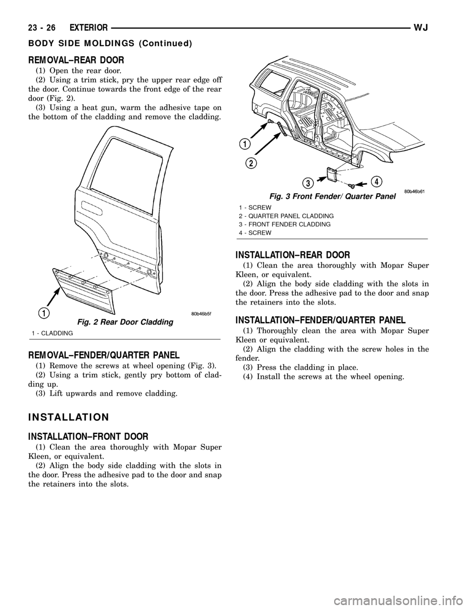
REMOVAL±REAR DOOR
(1) Open the rear door.
(2) Using a trim stick, pry the upper rear edge off
the door. Continue towards the front edge of the rear
door (Fig. 2).
(3) Using a heat gun, warm the adhesive tape on
the bottom of the cladding and remove the cladding.
REMOVAL±FENDER/QUARTER PANEL
(1) Remove the screws at wheel opening (Fig. 3).
(2) Using a trim stick, gently pry bottom of clad-
ding up.
(3) Lift upwards and remove cladding.
INSTALLATION
INSTALLATION±FRONT DOOR
(1) Clean the area thoroughly with Mopar Super
Kleen, or equivalent.
(2) Align the body side cladding with the slots in
the door. Press the adhesive pad to the door and snap
the retainers into the slots.
INSTALLATION±REAR DOOR
(1) Clean the area thoroughly with Mopar Super
Kleen, or equivalent.
(2) Align the body side cladding with the slots in
the door. Press the adhesive pad to the door and snap
the retainers into the slots.
INSTALLATION±FENDER/QUARTER PANEL
(1) Thoroughly clean the area with Mopar Super
Kleen or equivalent.
(2) Align the cladding with the screw holes in the
fender.
(3) Press the cladding in place.
(4) Install the screws at the wheel opening.
Fig. 2 Rear Door Cladding
1 - CLADDING
Fig. 3 Front Fender/ Quarter Panel
1 - SCREW
2 - QUARTER PANEL CLADDING
3 - FRONT FENDER CLADDING
4 - SCREW
23 - 26 EXTERIORWJ
BODY SIDE MOLDINGS (Continued)
Page 1900 of 2199
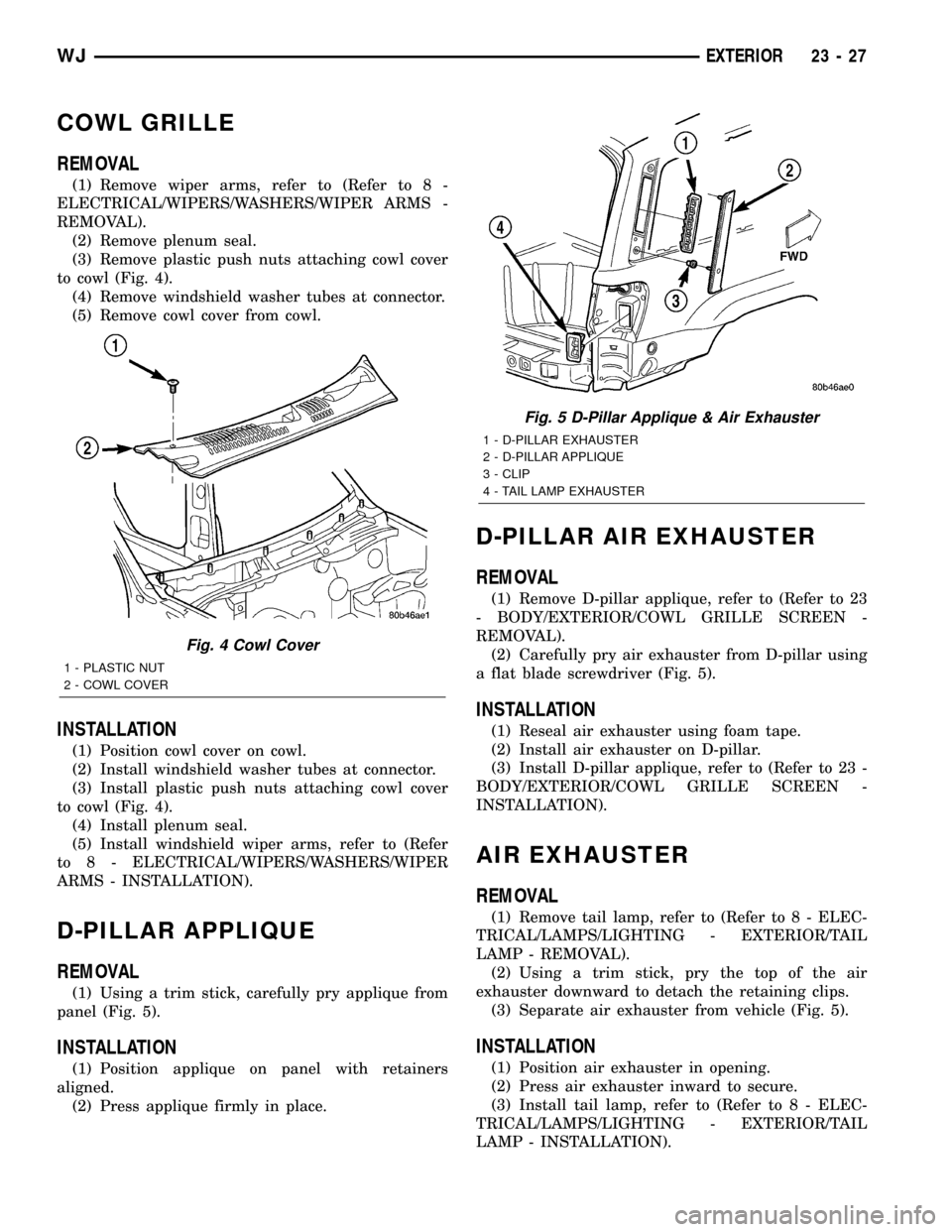
COWL GRILLE
REMOVAL
(1) Remove wiper arms, refer to (Refer to 8 -
ELECTRICAL/WIPERS/WASHERS/WIPER ARMS -
REMOVAL).
(2) Remove plenum seal.
(3) Remove plastic push nuts attaching cowl cover
to cowl (Fig. 4).
(4) Remove windshield washer tubes at connector.
(5) Remove cowl cover from cowl.
INSTALLATION
(1) Position cowl cover on cowl.
(2) Install windshield washer tubes at connector.
(3) Install plastic push nuts attaching cowl cover
to cowl (Fig. 4).
(4) Install plenum seal.
(5) Install windshield wiper arms, refer to (Refer
to 8 - ELECTRICAL/WIPERS/WASHERS/WIPER
ARMS - INSTALLATION).
D-PILLAR APPLIQUE
REMOVAL
(1) Using a trim stick, carefully pry applique from
panel (Fig. 5).
INSTALLATION
(1) Position applique on panel with retainers
aligned.
(2) Press applique firmly in place.
D-PILLAR AIR EXHAUSTER
REMOVAL
(1) Remove D-pillar applique, refer to (Refer to 23
- BODY/EXTERIOR/COWL GRILLE SCREEN -
REMOVAL).
(2) Carefully pry air exhauster from D-pillar using
a flat blade screwdriver (Fig. 5).
INSTALLATION
(1) Reseal air exhauster using foam tape.
(2) Install air exhauster on D-pillar.
(3) Install D-pillar applique, refer to (Refer to 23 -
BODY/EXTERIOR/COWL GRILLE SCREEN -
INSTALLATION).
AIR EXHAUSTER
REMOVAL
(1) Remove tail lamp, refer to (Refer to 8 - ELEC-
TRICAL/LAMPS/LIGHTING - EXTERIOR/TAIL
LAMP - REMOVAL).
(2) Using a trim stick, pry the top of the air
exhauster downward to detach the retaining clips.
(3) Separate air exhauster from vehicle (Fig. 5).
INSTALLATION
(1) Position air exhauster in opening.
(2) Press air exhauster inward to secure.
(3) Install tail lamp, refer to (Refer to 8 - ELEC-
TRICAL/LAMPS/LIGHTING - EXTERIOR/TAIL
LAMP - INSTALLATION).
Fig. 4 Cowl Cover
1 - PLASTIC NUT
2 - COWL COVER
Fig. 5 D-Pillar Applique & Air Exhauster
1 - D-PILLAR EXHAUSTER
2 - D-PILLAR APPLIQUE
3 - CLIP
4 - TAIL LAMP EXHAUSTER
WJEXTERIOR 23 - 27