Ecu JEEP GRAND CHEROKEE 2002 WJ / 2.G User Guide
[x] Cancel search | Manufacturer: JEEP, Model Year: 2002, Model line: GRAND CHEROKEE, Model: JEEP GRAND CHEROKEE 2002 WJ / 2.GPages: 2199, PDF Size: 76.01 MB
Page 103 of 2199
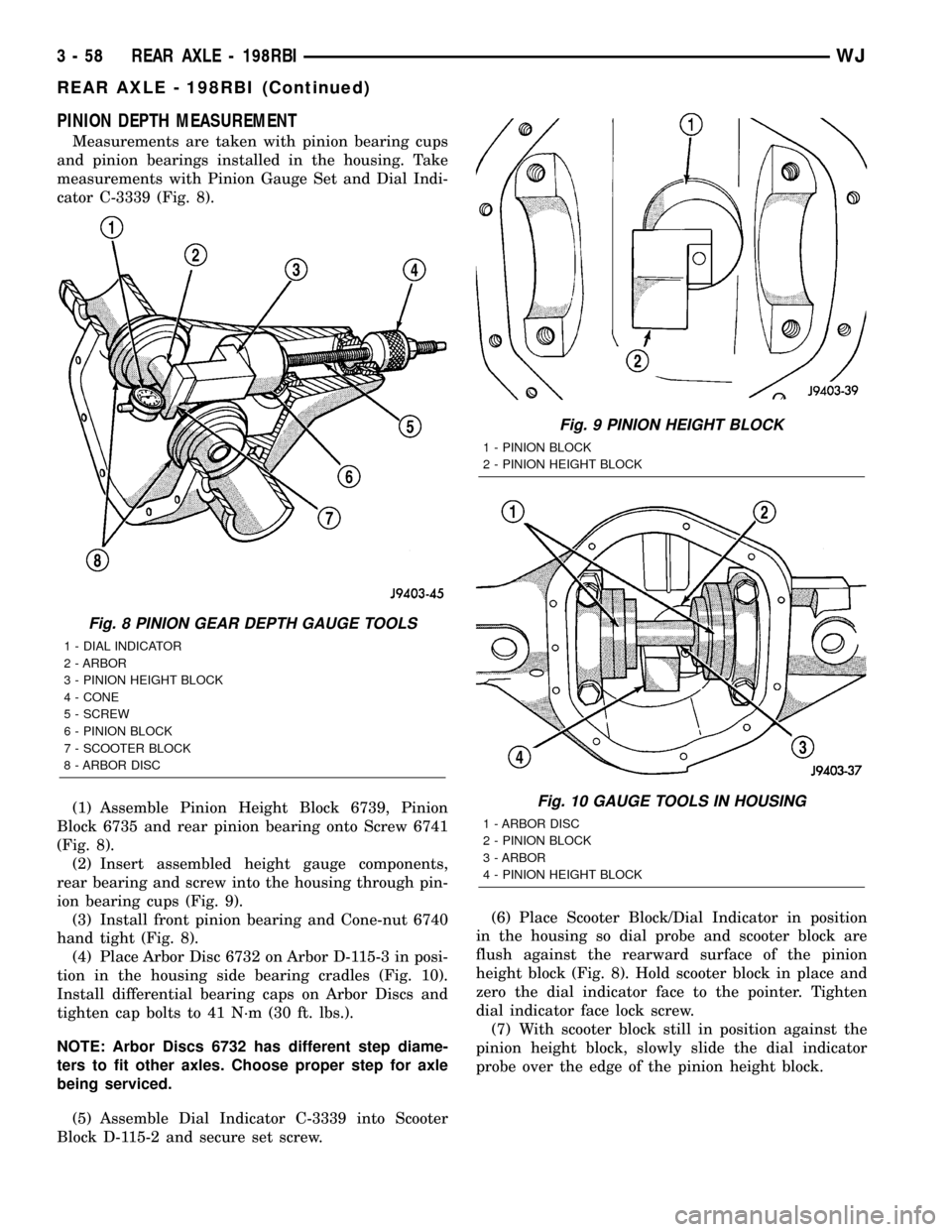
PINION DEPTH MEASUREMENT
Measurements are taken with pinion bearing cups
and pinion bearings installed in the housing. Take
measurements with Pinion Gauge Set and Dial Indi-
cator C-3339 (Fig. 8).
(1) Assemble Pinion Height Block 6739, Pinion
Block 6735 and rear pinion bearing onto Screw 6741
(Fig. 8).
(2) Insert assembled height gauge components,
rear bearing and screw into the housing through pin-
ion bearing cups (Fig. 9).
(3) Install front pinion bearing and Cone-nut 6740
hand tight (Fig. 8).
(4) Place Arbor Disc 6732 on Arbor D-115-3 in posi-
tion in the housing side bearing cradles (Fig. 10).
Install differential bearing caps on Arbor Discs and
tighten cap bolts to 41 N´m (30 ft. lbs.).
NOTE: Arbor Discs 6732 has different step diame-
ters to fit other axles. Choose proper step for axle
being serviced.
(5) Assemble Dial Indicator C-3339 into Scooter
Block D-115-2 and secure set screw.(6) Place Scooter Block/Dial Indicator in position
in the housing so dial probe and scooter block are
flush against the rearward surface of the pinion
height block (Fig. 8). Hold scooter block in place and
zero the dial indicator face to the pointer. Tighten
dial indicator face lock screw.
(7) With scooter block still in position against the
pinion height block, slowly slide the dial indicator
probe over the edge of the pinion height block.
Fig. 8 PINION GEAR DEPTH GAUGE TOOLS
1 - DIAL INDICATOR
2 - ARBOR
3 - PINION HEIGHT BLOCK
4 - CONE
5 - SCREW
6 - PINION BLOCK
7 - SCOOTER BLOCK
8 - ARBOR DISC
Fig. 9 PINION HEIGHT BLOCK
1 - PINION BLOCK
2 - PINION HEIGHT BLOCK
Fig. 10 GAUGE TOOLS IN HOUSING
1 - ARBOR DISC
2 - PINION BLOCK
3 - ARBOR
4 - PINION HEIGHT BLOCK
3 - 58 REAR AXLE - 198RBIWJ
REAR AXLE - 198RBI (Continued)
Page 127 of 2199
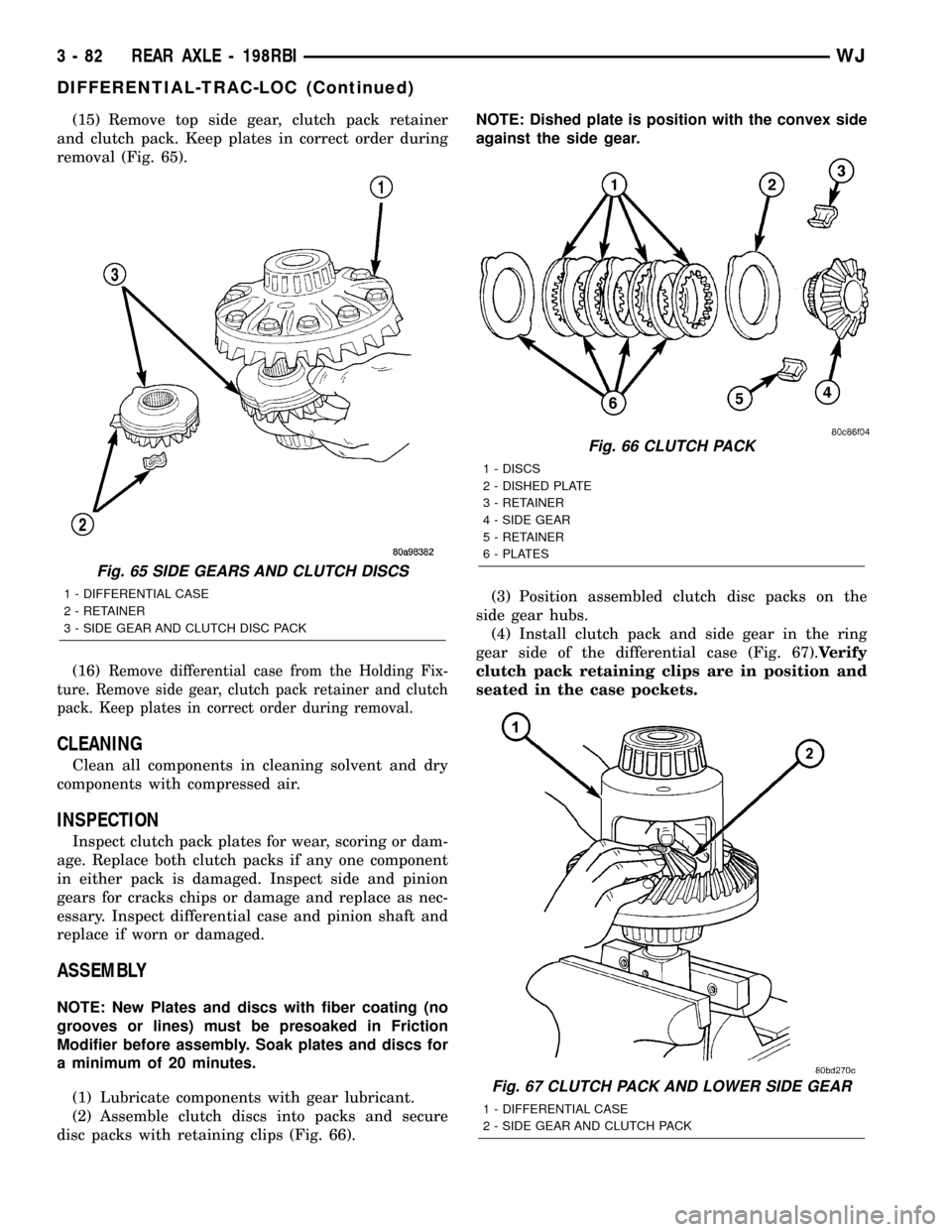
(15) Remove top side gear, clutch pack retainer
and clutch pack. Keep plates in correct order during
removal (Fig. 65).
(16)
Remove differential case from the Holding Fix-
ture. Remove side gear, clutch pack retainer and clutch
pack. Keep plates in correct order during removal.
CLEANING
Clean all components in cleaning solvent and dry
components with compressed air.
INSPECTION
Inspect clutch pack plates for wear, scoring or dam-
age. Replace both clutch packs if any one component
in either pack is damaged. Inspect side and pinion
gears for cracks chips or damage and replace as nec-
essary. Inspect differential case and pinion shaft and
replace if worn or damaged.
ASSEMBLY
NOTE: New Plates and discs with fiber coating (no
grooves or lines) must be presoaked in Friction
Modifier before assembly. Soak plates and discs for
a minimum of 20 minutes.
(1) Lubricate components with gear lubricant.
(2) Assemble clutch discs into packs and secure
disc packs with retaining clips (Fig. 66).NOTE: Dished plate is position with the convex side
against the side gear.
(3) Position assembled clutch disc packs on the
side gear hubs.
(4) Install clutch pack and side gear in the ring
gear side of the differential case (Fig. 67).Verify
clutch pack retaining clips are in position and
seated in the case pockets.
Fig. 65 SIDE GEARS AND CLUTCH DISCS
1 - DIFFERENTIAL CASE
2 - RETAINER
3 - SIDE GEAR AND CLUTCH DISC PACK
Fig. 66 CLUTCH PACK
1 - DISCS
2 - DISHED PLATE
3 - RETAINER
4 - SIDE GEAR
5 - RETAINER
6 - PLATES
Fig. 67 CLUTCH PACK AND LOWER SIDE GEAR
1 - DIFFERENTIAL CASE
2 - SIDE GEAR AND CLUTCH PACK
3 - 82 REAR AXLE - 198RBIWJ
DIFFERENTIAL-TRAC-LOC (Continued)
Page 140 of 2199
Condition Possible Causes Correction
Gear Teeth Broke 1. Overloading. 1. Replace gears. Examine other
gears and bearings for possible
damage.
2. Erratic clutch operation. 2. Replace gears and examine the
remaining parts for damage. Avoid
erratic clutch operation.
3. Ice-spotted pavement. 3. Replace gears and examine
remaining parts for damage.
4. Improper adjustments. 4. Replace gears and examine
remaining parts for damage. Ensure
ring gear backlash is correct.
Axle Noise 1. Insufficient lubricant. 1. Fill differential with the correct
fluid type and quantity.
2. Improper ring gear and pinion
adjustment.2. Check ring gear and pinion
contact pattern.
3. Unmatched ring gear and pinion. 3. Replace gears with a matched
ring gear and pinion.
4. Worn teeth on ring gear and/or
pinion.4. Replace ring gear and pinion.
5. Loose pinion bearings. 5. Adjust pinion bearing pre-load.
6. Loose differential bearings. 6. Adjust differential bearing
pre-load.
7. Mis-aligned or sprung ring gear. 7. Measure ring gear run-out.
Replace components as necessary.
8. Loose differential bearing cap
bolts.8. Inspect differential components
and replace as necessary. Ensure
that the bearing caps are torqued
tot he proper specification.
9. Housing not machined properly. 9. Replace housing.
VARI-LOKT
(1) Park the vehicle on a level surface or raise
vehicle on hoist so that the vehicle is level.
(2) Remove the axle fill plug.
(3) Verify that the axle fluid level is correct. The
fluid level is correct if the fluid is level with the bot-
tom of the fill hole.
(4) Shift the transfer case into the 4WD full-time
position.
(5) Drive the vehicle in a tight circle for 2 minutes
at 5mph to fully prime the pump.
(6) Block the tires opposite the axle to be tested to
prevent the vehicle from moving.
(7) Shift the transfer case into the 4WD Low posi-
tion and the transmission into the Park position.
(8) Raise both the wheels of the axle to be tested
off of the ground.(9) Rotate the left wheel by hand at a minimum of
one revolution per second while an assistant rotates
the right wheel in the opposite direction.
(10) The left wheel should spin freely at first and
then increase in resistance within 5 revolutions until
the wheels cannot be continuously rotated in opposite
directions.
(11) The Vari-loktdifferential has engaged prop-
erly if the wheels cannot be rotated in opposite direc-
tions for a moment. After the wheels stop rotating for
a moment, the fluid pressure will drop in the differ-
ential and the wheels begin to rotate once again.
(12) If the system does not operate properly,
replace the Vari-loktdifferential.
REMOVAL
(1) Raise and support the vehicle.
(2) Position a lifting device under the axle and
secure axle.
WJREAR AXLE - 226RBA 3 - 95
REAR AXLE - 226RBA (Continued)
Page 144 of 2199
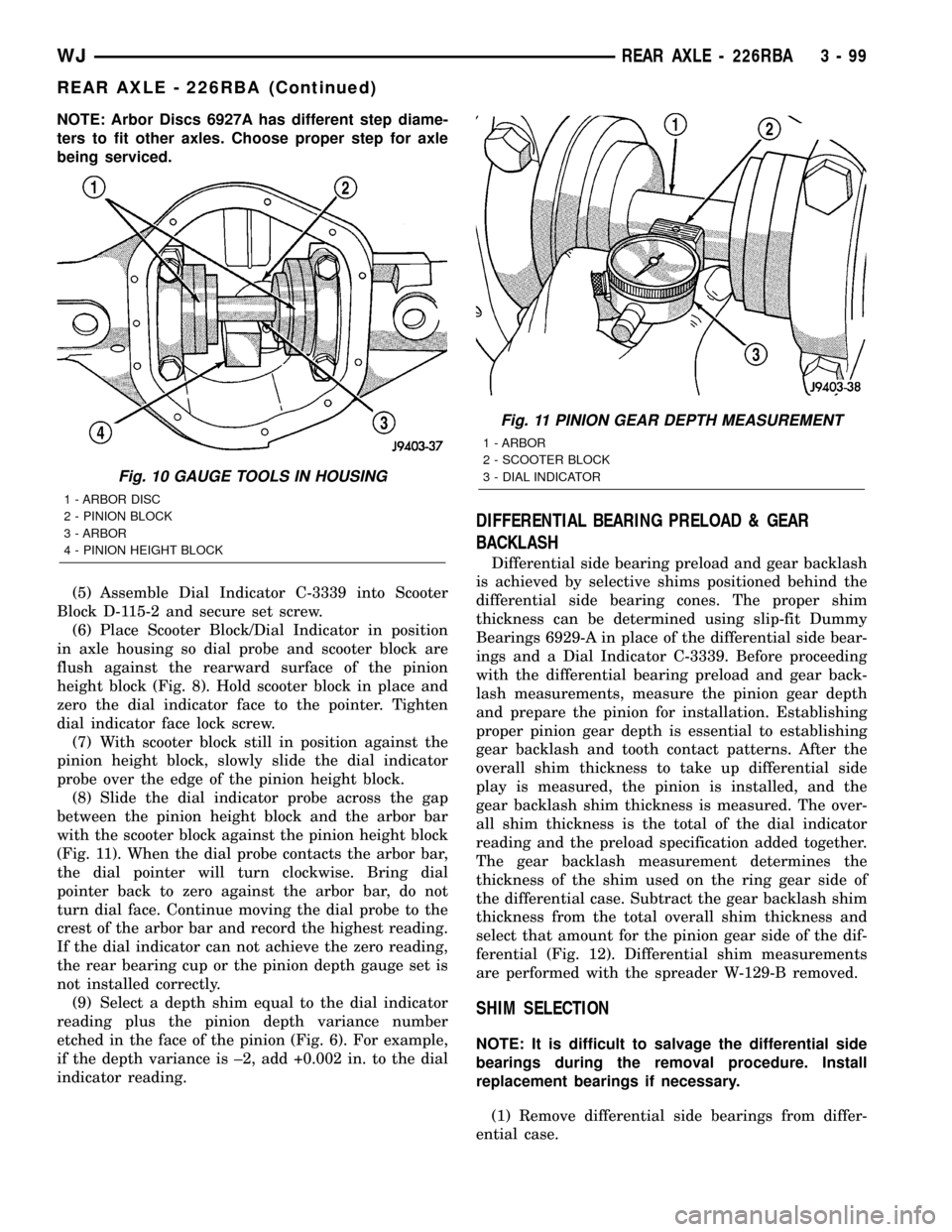
NOTE: Arbor Discs 6927A has different step diame-
ters to fit other axles. Choose proper step for axle
being serviced.
(5) Assemble Dial Indicator C-3339 into Scooter
Block D-115-2 and secure set screw.
(6) Place Scooter Block/Dial Indicator in position
in axle housing so dial probe and scooter block are
flush against the rearward surface of the pinion
height block (Fig. 8). Hold scooter block in place and
zero the dial indicator face to the pointer. Tighten
dial indicator face lock screw.
(7) With scooter block still in position against the
pinion height block, slowly slide the dial indicator
probe over the edge of the pinion height block.
(8) Slide the dial indicator probe across the gap
between the pinion height block and the arbor bar
with the scooter block against the pinion height block
(Fig. 11). When the dial probe contacts the arbor bar,
the dial pointer will turn clockwise. Bring dial
pointer back to zero against the arbor bar, do not
turn dial face. Continue moving the dial probe to the
crest of the arbor bar and record the highest reading.
If the dial indicator can not achieve the zero reading,
the rear bearing cup or the pinion depth gauge set is
not installed correctly.
(9) Select a depth shim equal to the dial indicator
reading plus the pinion depth variance number
etched in the face of the pinion (Fig. 6). For example,
if the depth variance is ±2, add +0.002 in. to the dial
indicator reading.
DIFFERENTIAL BEARING PRELOAD & GEAR
BACKLASH
Differential side bearing preload and gear backlash
is achieved by selective shims positioned behind the
differential side bearing cones. The proper shim
thickness can be determined using slip-fit Dummy
Bearings 6929-A in place of the differential side bear-
ings and a Dial Indicator C-3339. Before proceeding
with the differential bearing preload and gear back-
lash measurements, measure the pinion gear depth
and prepare the pinion for installation. Establishing
proper pinion gear depth is essential to establishing
gear backlash and tooth contact patterns. After the
overall shim thickness to take up differential side
play is measured, the pinion is installed, and the
gear backlash shim thickness is measured. The over-
all shim thickness is the total of the dial indicator
reading and the preload specification added together.
The gear backlash measurement determines the
thickness of the shim used on the ring gear side of
the differential case. Subtract the gear backlash shim
thickness from the total overall shim thickness and
select that amount for the pinion gear side of the dif-
ferential (Fig. 12). Differential shim measurements
are performed with the spreader W-129-B removed.
SHIM SELECTION
NOTE: It is difficult to salvage the differential side
bearings during the removal procedure. Install
replacement bearings if necessary.
(1) Remove differential side bearings from differ-
ential case.
Fig. 10 GAUGE TOOLS IN HOUSING
1 - ARBOR DISC
2 - PINION BLOCK
3 - ARBOR
4 - PINION HEIGHT BLOCK
Fig. 11 PINION GEAR DEPTH MEASUREMENT
1 - ARBOR
2 - SCOOTER BLOCK
3 - DIAL INDICATOR
WJREAR AXLE - 226RBA 3 - 99
REAR AXLE - 226RBA (Continued)
Page 167 of 2199
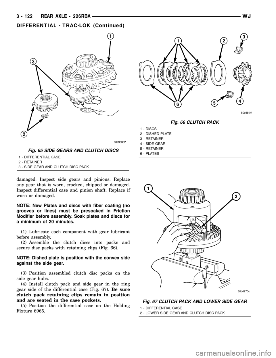
damaged. Inspect side gears and pinions. Replace
any gear that is worn, cracked, chipped or damaged.
Inspect differential case and pinion shaft. Replace if
worn or damaged.
NOTE: New Plates and discs with fiber coating (no
grooves or lines) must be presoaked in Friction
Modifier before assembly. Soak plates and discs for
a minimum of 20 minutes.
(1) Lubricate each component with gear lubricant
before assembly.
(2) Assemble the clutch discs into packs and
secure disc packs with retaining clips (Fig. 66).
NOTE: Dished plate is position with the convex side
against the side gear.
(3) Position assembled clutch disc packs on the
side gear hubs.
(4) Install clutch pack and side gear in the ring
gear side of the differential case (Fig. 67).Be sure
clutch pack retaining clips remain in position
and are seated in the case pockets.
(5) Position the differential case on the Holding
Fixture 6965.
Fig. 65 SIDE GEARS AND CLUTCH DISCS
1 - DIFFERENTIAL CASE
2 - RETAINER
3 - SIDE GEAR AND CLUTCH DISC PACK
Fig. 66 CLUTCH PACK
1 - DISCS
2 - DISHED PLATE
3 - RETAINER
4 - SIDE GEAR
5 - RETAINER
6 - PLATES
Fig. 67 CLUTCH PACK AND LOWER SIDE GEAR
1 - DIFFERENTIAL CASE
2 - LOWER SIDE GEAR AND CLUTCH DISC PACK
3 - 122 REAR AXLE - 226RBAWJ
DIFFERENTIAL - TRAC-LOK (Continued)
Page 180 of 2199
NOTE: The front outer brake shoes are equipped
with a wear indicator. The indicator will produce an
audible noise when it contacts the rotor surface.
BRAKE CHATTER
Brake chatter is usually caused by loose or worn
components, or glazed/burnt lining. Rotors with hard
spots can also contribute to chatter. Additional causes
of chatter are out-of-tolerance rotors, brake lining not
securely attached to the shoes, loose wheel bearings
and contaminated brake lining.
THUMP/CLUNK NOISE
Thumping or clunk noises during braking are fre-
quentlynotcaused by brake components. In many
cases, such noises are caused by loose or damaged
steering, suspension, or engine components.
STANDARD PROCEDURE
STANDARD PROCEDURE - MANUAL BLEEDING
Use Mopar brake fluid, or an equivalent quality
fluid meeting SAE J1703-F and DOT 3 standards
only. Use fresh, clean fluid from a sealed container at
all times.
Do not pump the brake pedal at any time while
bleeding. Air in the system will be compressed into
small bubbles that are distributed throughout the
hydraulic system. This will make additional bleeding
operations necessary.
Do not allow the master cylinder to run out of fluid
during bleed operations. An empty cylinder will allow
additional air to be drawn into the system. Check the
cylinder fluid level frequently and add fluid as
needed.
Bleed only one brake component at a time in the
following sequence:
(1) Fill the master cylinder reservoir with brake
fluid.
(2) If calipers are overhauled, open all caliper
bleed screws. Then close each bleed screw as fluid
starts to drip from it. Top off master cylinder reser-
voir once more before proceeding.
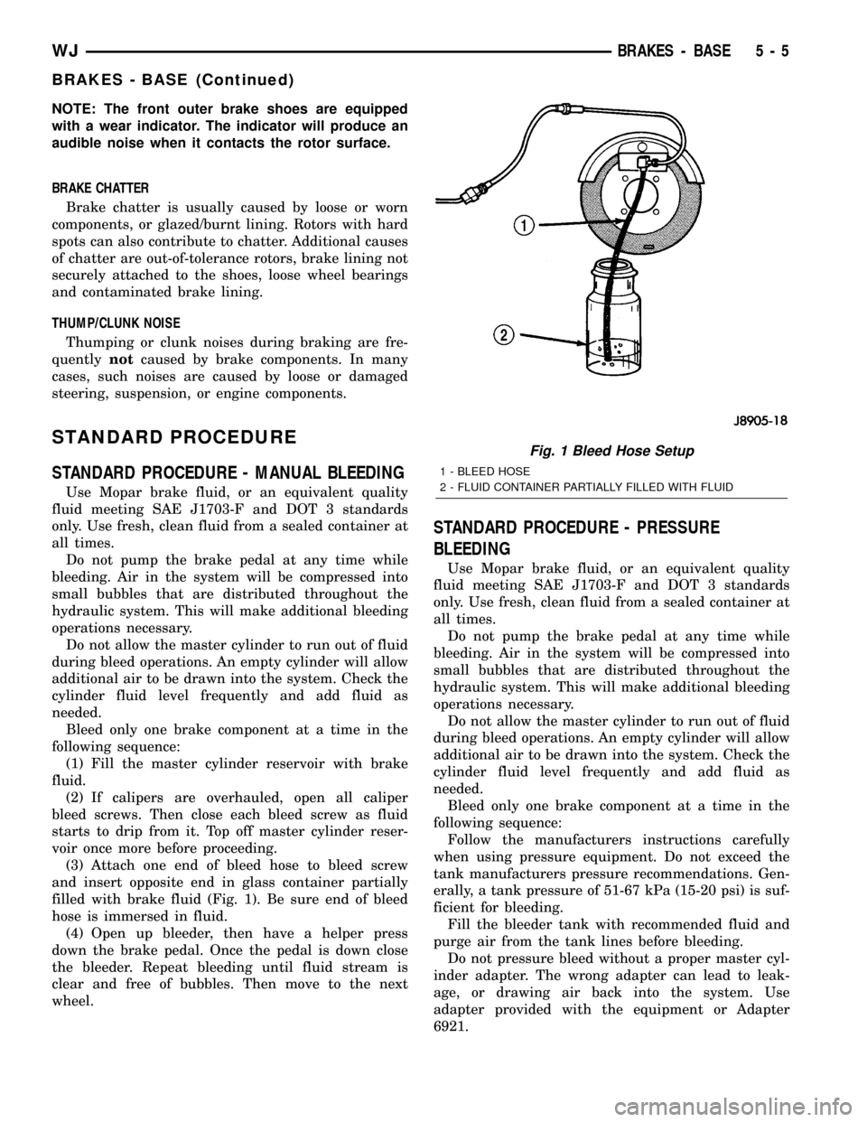
(3) Attach one end of bleed hose to bleed screw
and insert opposite end in glass container partially
filled with brake fluid (Fig. 1). Be sure end of bleed
hose is immersed in fluid.
(4) Open up bleeder, then have a helper press
down the brake pedal. Once the pedal is down close
the bleeder. Repeat bleeding until fluid stream is
clear and free of bubbles. Then move to the next
wheel.
STANDARD PROCEDURE - PRESSURE
BLEEDING
Use Mopar brake fluid, or an equivalent quality
fluid meeting SAE J1703-F and DOT 3 standards
only. Use fresh, clean fluid from a sealed container at
all times.
Do not pump the brake pedal at any time while
bleeding. Air in the system will be compressed into
small bubbles that are distributed throughout the
hydraulic system. This will make additional bleeding
operations necessary.
Do not allow the master cylinder to run out of fluid
during bleed operations. An empty cylinder will allow
additional air to be drawn into the system. Check the
cylinder fluid level frequently and add fluid as
needed.
Bleed only one brake component at a time in the
following sequence:
Follow the manufacturers instructions carefully
when using pressure equipment. Do not exceed the
tank manufacturers pressure recommendations. Gen-
erally, a tank pressure of 51-67 kPa (15-20 psi) is suf-
ficient for bleeding.
Fill the bleeder tank with recommended fluid and
purge air from the tank lines before bleeding.
Do not pressure bleed without a proper master cyl-
inder adapter. The wrong adapter can lead to leak-
age, or drawing air back into the system. Use
adapter provided with the equipment or Adapter
6921.
Fig. 1 Bleed Hose Setup
1 - BLEED HOSE
2 - FLUID CONTAINER PARTIALLY FILLED WITH FLUID
WJBRAKES - BASE 5 - 5
BRAKES - BASE (Continued)
Page 185 of 2199
BRAKE PADS / SHOES
DESCRIPTION
DESCRIPTION - FRONT DISC BRAKE SHOES
The calipers are twin piston type. The calipers are
free to slide laterally on the anchor, this allows con-
tinuous compensation for lining wear.
DESCRIPTION - REAR DISC BRAKE SHOES
The rear disc brakes consist of single piston float-
ing-type calipers and solid rotors. The rear caliper is
mounted on an anchor attached to an adapter
attached the rear axle tube flange. The anchors are
secured to the adapters with mounting bolts. The
disc brake rotor splash shield is part of the adaptor.
The disc brake rotor has a built in brake drum used
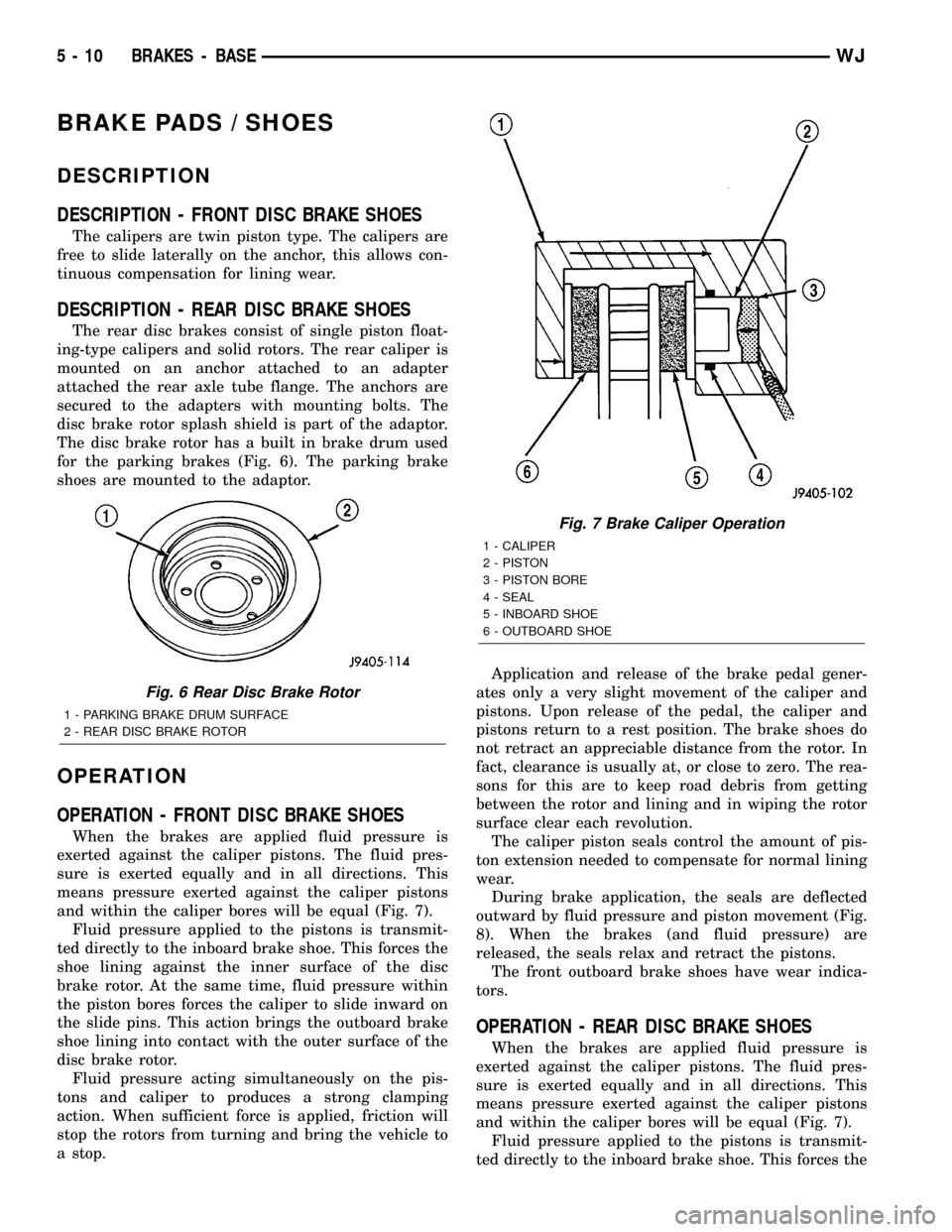
for the parking brakes (Fig. 6). The parking brake
shoes are mounted to the adaptor.
OPERATION
OPERATION - FRONT DISC BRAKE SHOES
When the brakes are applied fluid pressure is
exerted against the caliper pistons. The fluid pres-
sure is exerted equally and in all directions. This
means pressure exerted against the caliper pistons
and within the caliper bores will be equal (Fig. 7).
Fluid pressure applied to the pistons is transmit-
ted directly to the inboard brake shoe. This forces the
shoe lining against the inner surface of the disc
brake rotor. At the same time, fluid pressure within
the piston bores forces the caliper to slide inward on
the slide pins. This action brings the outboard brake
shoe lining into contact with the outer surface of the
disc brake rotor.
Fluid pressure acting simultaneously on the pis-
tons and caliper to produces a strong clamping
action. When sufficient force is applied, friction will
stop the rotors from turning and bring the vehicle to
a stop.Application and release of the brake pedal gener-
ates only a very slight movement of the caliper and
pistons. Upon release of the pedal, the caliper and
pistons return to a rest position. The brake shoes do
not retract an appreciable distance from the rotor. In
fact, clearance is usually at, or close to zero. The rea-
sons for this are to keep road debris from getting
between the rotor and lining and in wiping the rotor
surface clear each revolution.
The caliper piston seals control the amount of pis-
ton extension needed to compensate for normal lining
wear.
During brake application, the seals are deflected
outward by fluid pressure and piston movement (Fig.
8). When the brakes (and fluid pressure) are
released, the seals relax and retract the pistons.
The front outboard brake shoes have wear indica-
tors.
OPERATION - REAR DISC BRAKE SHOES
When the brakes are applied fluid pressure is
exerted against the caliper pistons. The fluid pres-
sure is exerted equally and in all directions. This
means pressure exerted against the caliper pistons
and within the caliper bores will be equal (Fig. 7).
Fluid pressure applied to the pistons is transmit-
ted directly to the inboard brake shoe. This forces the
Fig. 6 Rear Disc Brake Rotor
1 - PARKING BRAKE DRUM SURFACE
2 - REAR DISC BRAKE ROTOR
Fig. 7 Brake Caliper Operation
1 - CALIPER
2 - PISTON
3 - PISTON BORE
4 - SEAL
5 - INBOARD SHOE
6 - OUTBOARD SHOE
5 - 10 BRAKES - BASEWJ
Page 187 of 2199
(8) Secure caliper to nearby suspension part with
wire.Do not allow brake hose to support caliper
weight.
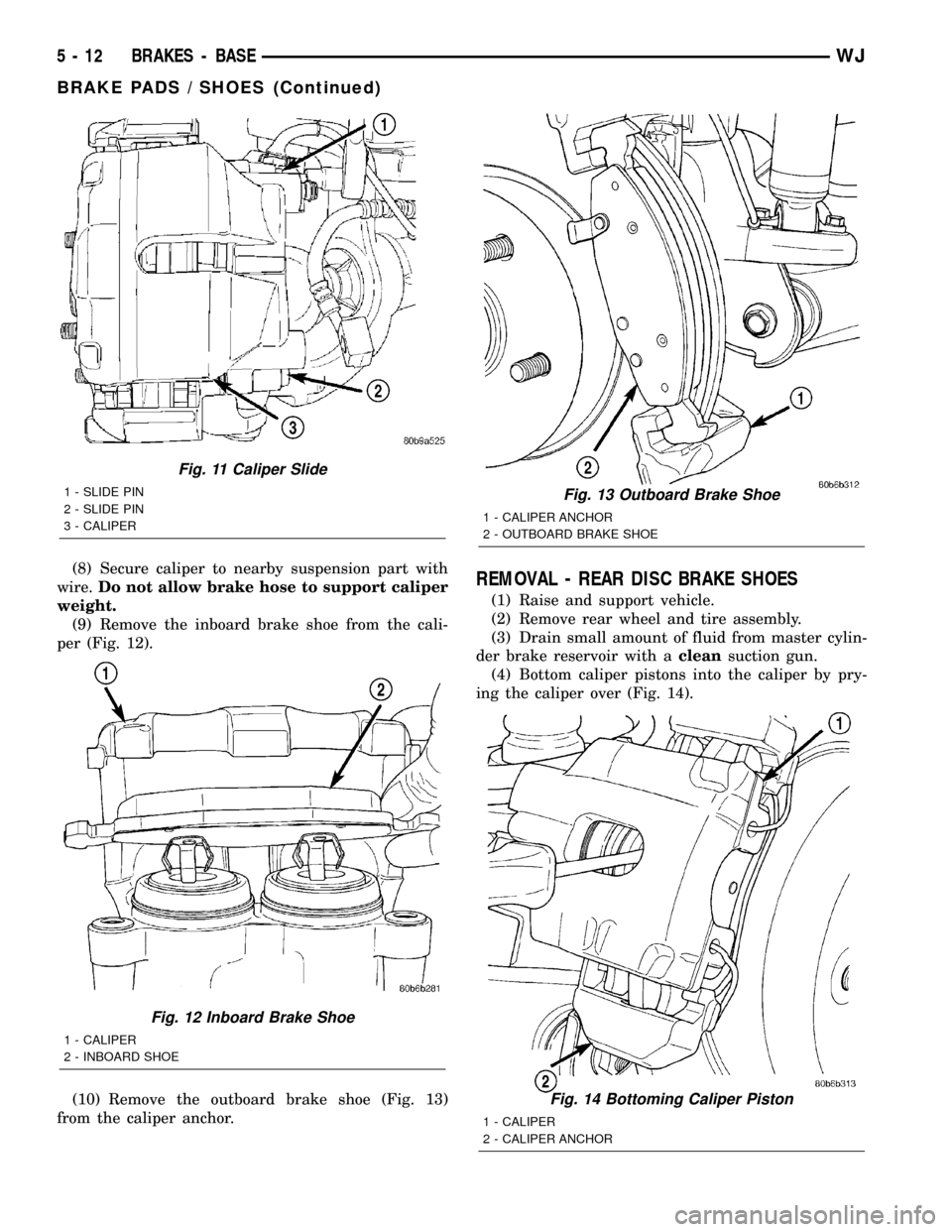
(9) Remove the inboard brake shoe from the cali-
per (Fig. 12).
(10) Remove the outboard brake shoe (Fig. 13)
from the caliper anchor.REMOVAL - REAR DISC BRAKE SHOES
(1) Raise and support vehicle.
(2) Remove rear wheel and tire assembly.
(3) Drain small amount of fluid from master cylin-
der brake reservoir with acleansuction gun.
(4) Bottom caliper pistons into the caliper by pry-
ing the caliper over (Fig. 14).
Fig. 11 Caliper Slide
1 - SLIDE PIN
2 - SLIDE PIN
3 - CALIPER
Fig. 12 Inboard Brake Shoe
1 - CALIPER
2 - INBOARD SHOE
Fig. 13 Outboard Brake Shoe
1 - CALIPER ANCHOR
2 - OUTBOARD BRAKE SHOE
Fig. 14 Bottoming Caliper Piston
1 - CALIPER
2 - CALIPER ANCHOR
5 - 12 BRAKES - BASEWJ
BRAKE PADS / SHOES (Continued)
Page 188 of 2199
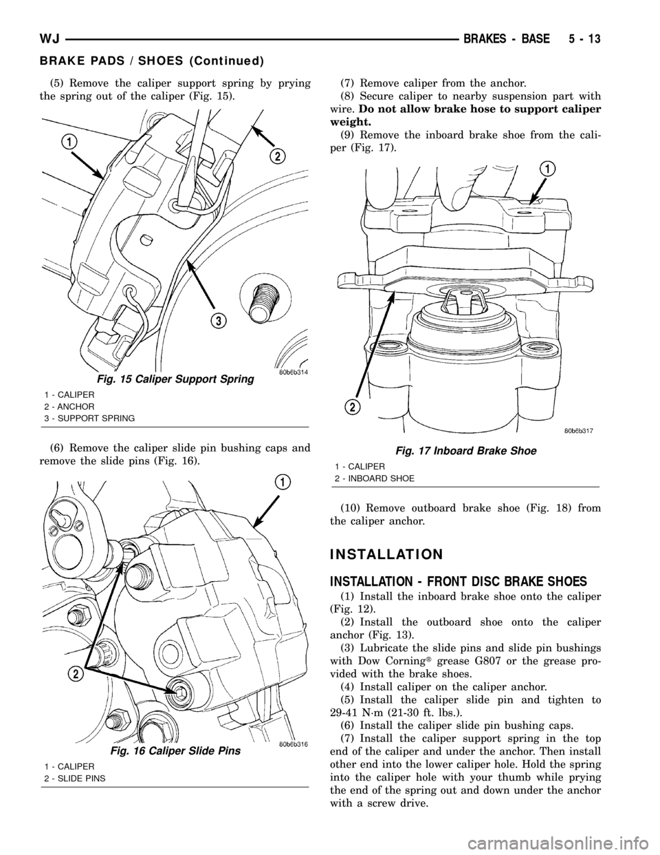
(5) Remove the caliper support spring by prying
the spring out of the caliper (Fig. 15).
(6) Remove the caliper slide pin bushing caps and
remove the slide pins (Fig. 16).(7) Remove caliper from the anchor.
(8) Secure caliper to nearby suspension part with
wire.Do not allow brake hose to support caliper
weight.
(9) Remove the inboard brake shoe from the cali-
per (Fig. 17).
(10) Remove outboard brake shoe (Fig. 18) from
the caliper anchor.
INSTALLATION
INSTALLATION - FRONT DISC BRAKE SHOES
(1) Install the inboard brake shoe onto the caliper
(Fig. 12).
(2) Install the outboard shoe onto the caliper
anchor (Fig. 13).
(3) Lubricate the slide pins and slide pin bushings
with Dow Corningtgrease G807 or the grease pro-
vided with the brake shoes.
(4) Install caliper on the caliper anchor.
(5) Install the caliper slide pin and tighten to
29-41 N´m (21-30 ft. lbs.).
(6) Install the caliper slide pin bushing caps.
(7) Install the caliper support spring in the top
end of the caliper and under the anchor. Then install
other end into the lower caliper hole. Hold the spring
into the caliper hole with your thumb while prying
the end of the spring out and down under the anchor
with a screw drive.
Fig. 15 Caliper Support Spring
1 - CALIPER
2 - ANCHOR
3 - SUPPORT SPRING
Fig. 16 Caliper Slide Pins
1 - CALIPER
2 - SLIDE PINS
Fig. 17 Inboard Brake Shoe
1 - CALIPER
2 - INBOARD SHOE
WJBRAKES - BASE 5 - 13
BRAKE PADS / SHOES (Continued)
Page 206 of 2199
REMOVAL
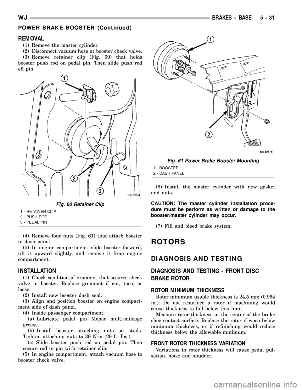
(1) Remove the master cylinder.
(2) Disconnect vacuum hose at booster check valve.
(3) Remove retainer clip (Fig. 60) that holds
booster push rod on pedal pin. Then slide push rod
off pin.
(4) Remove four nuts (Fig. 61) that attach booster
to dash panel.
(5) In engine compartment, slide booster forward,
tilt it upward slightly, and remove it from engine
compartment.
INSTALLATION
(1) Check condition of grommet that secures check
valve in booster. Replace grommet if cut, torn, or
loose.
(2) Install new booster dash seal.
(3) Align and position booster on engine compart-
ment side of dash panel.
(4) Inside passenger compartment:
(a) Lubricate pedal pin Mopar multi-mileage
grease.
(b) Install booster attaching nuts on studs.
Tighten attaching nuts to 39 N´m (29 ft. lbs.).
(c) Slide booster push rod on pedal pin. Then
secure rod to pin with retainer clip.
(5) In engine compartment, attach vacuum hose to
booster check valve.(6) Install the master cylinder with new gasket
and nuts.
CAUTION: The master cylinder installation proce-
dure must be perform as written or damage to the
booster/master cylinder may occur.
(7) Fill and bleed brake system.
ROTORS
DIAGNOSIS AND TESTING
DIAGNOSIS AND TESTING - FRONT DISC
BRAKE ROTOR
ROTOR MINIMUM THICKNESS
Rotor minimum usable thickness is 24.5 mm (0.964
in.). Do not resurface a rotor if machining would
cause thickness to fall below this limit.
Measure rotor thickness at the center of the brake
shoe contact surface. Replace the rotor if worn below
minimum thickness, or if refinishing would reduce
thickness below the allowable minimum.
FRONT ROTOR THICKNESS VARIATION
Variations in rotor thickness will cause pedal pul-
sation, noise and shudder.
Fig. 60 Retainer Clip
1 - RETAINER CLIP
2 - PUSH ROD
3 - PEDAL PIN
Fig. 61 Power Brake Booster Mounting
1 - BOOSTER
2 - DASH PANEL
WJBRAKES - BASE 5 - 31
POWER BRAKE BOOSTER (Continued)