Ecu JEEP GRAND CHEROKEE 2002 WJ / 2.G Workshop Manual
[x] Cancel search | Manufacturer: JEEP, Model Year: 2002, Model line: GRAND CHEROKEE, Model: JEEP GRAND CHEROKEE 2002 WJ / 2.GPages: 2199, PDF Size: 76.01 MB
Page 1 of 2199
GROUP TAB LOCATOR
Introduction
0Lubrication & Maintenance
2Suspension
3Driveline
5Brakes
7Cooling
8AAudio
8BChime/Buzzer
8EElectronic Control Modules
8FEngine Systems
8GHeated Systems
8HHorn
8IIgnition Control
8JInstrument Cluster
8LLamps
8MMessage Systems
8NPower Systems
8ORestraints
8PSpeed Control
8QVehicle Theft Security
8RWipers/Washers
8WWiring
9Engine
11Exhaust System
13Frame & Bumpers
14Fuel System
19Steering
21Transaxle
22Tires/Wheels
23Body
24Heating & Air Conditioning
25Emissions Control
Service Manual Comment Forms (Rear of Manual)
Page 17 of 2199

DESCRIPTION - ENGINE OIL - DIESEL
ENGINES
Use only Diesel Engine Oil meeting standardMIL-
2104Cor API ClassificationCD or higherorCCML
D4, D5.
SAE VISCOSITY GRADE
CAUTION: Low viscosity oils must have the proper
API quality or the CCMC G5 designation.
To assure of properly formulated engine oils, it is
recommended that SAE Grade 10W-40 engine oils
that meet Chrysler material standard MS-6395, be
used. European Grade 10W-40 oils are also accept-
able.
Oils of the SAE 5W-40 or 8W-80 grade number are
preferred when minimum temperatures consistently
fall below -12ÉC.
OPERATION - AUTOMATIC TRANSMISSION
FLUID
The automatic transmission fluid is selected based
upon several qualities. The fluid must provide a high
level of protection for the internal components by
providing a lubricating film between adjacent metal
components. The fluid must also be thermally stable
so that it can maintain a consistent viscosity through
a large temperature range. If the viscosity stays con-
stant through the temperature range of operation,
transmission operation and shift feel will remain con-
sistent. Transmission fluid must also be a good con-
ductor of heat. The fluid must absorb heat from the
internal transmission components and transfer that
heat to the transmission case.
FLUID FILL/CHECK
LOCATIONS
INSPECTION - FLUID FILL/CHECK LOCATIONS
The fluid fill/check locations and lubrication points
are located in each applicable group.
MAINTENANCE SCHEDULES
DESCRIPTION
9Maintenance Schedule Information not included in
this section, is located in the appropriate Owner's
Manual.9
LIFT POINTS
STANDARD PROCEDURE - HOISTING AND
JACKING RECOMMENDATIONS
FLOOR JACK
When properly positioned, a floor jack can be used
to lift a WJ vehicle (Fig. 7). Support the vehicle in
the raised position with jack stands at the front and
rear ends of the frame rails.
CAUTION: Do not attempt to lift a vehicle with a
floor jack positioned under:
²An axle tube.
²Aluminum differential.
²A body side sill.
²A steering linkage component.
²A drive shaft.
²The engine or transmission oil pan.
²The fuel tank.
²A front suspension arm.
HOIST
A vehicle can be lifted with:
²A single-post, frame-contact hoist.
²A twin-post, chassis hoist.
²A ramp-type, drive-on hoist.
NOTE: When a frame-contact type hoist is used,
verify that the lifting pads are positioned properly
(Fig. 7).
WARNING: THE HOISTING AND JACK LIFTING
POINTS PROVIDED ARE FOR A COMPLETE VEHI-
CLE. WHEN A CHASSIS OR DRIVETRAIN COMPO-
NENT IS REMOVED FROM A VEHICLE, THE
CENTER OF GRAVITY IS ALTERED MAKING SOME
HOISTING CONDITIONS UNSTABLE. PROPERLY
SUPPORT OR SECURE VEHICLE TO HOISTING
DEVICE WHEN THESE CONDITIONS EXIST.
0 - 6 LUBRICATION & MAINTENANCEWJ
FLUID TYPES (Continued)
Page 19 of 2199
DISCONNECT CABLE CLAMPS AS FOLLOWS:
²Disconnect BLACK cable clamp from engine
ground on disabled vehicle.
²When using a Booster vehicle, disconnect
BLACK cable clamp from battery negative terminal.
Disconnect RED cable clamp from battery positive
terminal.
²Disconnect RED cable clamp from battery posi-
tive terminal on disabled vehicle.
EMERGENCY TOW HOOKS
DESCRIPTION
WARNING: REMAIN AT A SAFE DISTANCE FROM A
VEHICLE THAT IS BEING TOWED VIA ITS TOW
HOOKS. THE TOW STRAPS/CHAINS COULD BREAK
AND CAUSE SERIOUS INJURY.
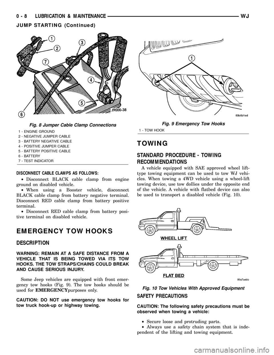
Some Jeep vehicles are equipped with front emer-
gency tow hooks (Fig. 9). The tow hooks should be
used forEMERGENCYpurposes only.
CAUTION: DO NOT use emergency tow hooks for
tow truck hook-up or highway towing.
TOWING
STANDARD PROCEDURE - TOWING
RECOMMENDATIONS
A vehicle equipped with SAE approved wheel lift-
type towing equipment can be used to tow WJ vehi-
cles. When towing a 4WD vehicle using a wheel-lift
towing device, use tow dollies under the opposite end
of the vehicle. A vehicle with flatbed device can also
be used to transport a disabled vehicle (Fig. 10).
SAFETY PRECAUTIONS
CAUTION: The following safety precautions must be
observed when towing a vehicle:
²Secure loose and protruding parts.
²Always use a safety chain system that is inde-
pendent of the lifting and towing equipment.
Fig. 8 Jumper Cable Clamp Connections
1 - ENGINE GROUND
2 - NEGATIVE JUMPER CABLE
3 - BATTERY NEGATIVE CABLE
4 - POSITIVE JUMPER CABLE
5 - BATTERY POSITIVE CABLE
6 - BATTERY
7 - TEST INDICATOR
Fig. 9 Emergency Tow Hooks
1 - TOW HOOK
Fig. 10 Tow Vehicles With Approved Equipment
0 - 8 LUBRICATION & MAINTENANCEWJ
JUMP STARTING (Continued)
Page 20 of 2199

²Do not allow towing equipment to contact the
disabled vehicle's fuel tank.
²Do not allow anyone under the disabled vehicle
while it is lifted by the towing device.
²Do not allow passengers to ride in a vehicle
being towed.
²Always observe state and local laws regarding
towing regulations.
²Do not tow a vehicle in a manner that could
jeopardize the safety of the operator, pedestrians or
other motorists.
²Do not attach tow chains, T-hooks, or J-hooks to
a bumper, steering linkage, drive shafts or a non-re-
inforced frame hole.
²Do not tow a heavily loaded vehicle. Use a flat-
bed device to transport a loaded vehicle.
TWO-WHEEL-DRIVE VEHICLE TOWING
DaimlerChrysler Corporation recommends that a
vehicle be towed with the rear end lifted, whenever
possible.
WARNING: WHEN TOWING A DISABLED VEHICLE
AND THE DRIVE WHEELS ARE SECURED IN A
WHEEL LIFT OR TOW DOLLIES, ENSURE THE
TRANSMISSION IS IN THE PARK POSITION (AUTO-
MATIC TRANSMISSION) OR A FORWARD DRIVE
GEAR (MANUAL TRANSMISSION).
WARNING: ENSURE VEHICLE IS ON A LEVEL SUR-
FACE OR THE WHEELS ARE BLOCKED TO PRE-
VENT VEHICLE FROM ROLLING.
TWO WHEEL DRIVE TOWING-REAR END LIFTED
CAUTION: Do not use steering column lock to
secure steering wheel during towing operation.
2WD vehicles can be towed with the front wheels
on the surface for extended distances at speeds not
exceeding 48 km/h (30 mph).
(1) Attach wheel lift device to rear wheels.
(2) Place the transmission in neutral.
(3) Raise vehicle to towing position.
(4) Attach safety chains. Route chains so not to
interfere with tail pipe when vehicle is lifted.
(5) Turn the ignition switch to the OFF position to
unlock the steering wheel.
CAUTION: Do not use steering column lock to
secure steering wheel during towing operation.
(6) Secure steering wheel in straight ahead posi-
tion with a clamp device designed for towing.
(7) Place transmission in park.
TWO WHEEL DRIVE TOWING-FRONT END LIFTED
CAUTION: Many vehicles are equipped with air
dams, spoilers, and/or ground effect panels. To
avoid component damage, a wheel-lift towing vehi-
cle or a flat-bed hauling vehicle is recommended.
(1) Attach wheel lift device to rear wheels.
(2) Place the transmission in neutral.
(3) Raise the rear of the vehicle off the ground and
install tow dollies under rear wheels.
(4) Attach wheel lift device to front wheels and
raise vehicle to towing position.
(5) Attach the safety chains.
CAUTION: Do not use steering column lock to
secure steering wheel during towing operation.
(6) Turn the ignition switch to the OFF position to
unlock the steering wheel.
(7) Secure steering wheel in straight ahead posi-
tion with a clamp device designed for towing.
(8) Place transmission in park.
FOUR-WHEEL-DRIVE VEHICLE TOWING
DaimlerChrysler Corporation recommends that a
4WD vehicle be transported on a flat-bed device. A
Wheel-lift device can be used providedthe trailing
wheels are off the ground and positioned in
tow dollies.
WARNING: WHEN TOWING A DISABLED VEHICLE
AND THE DRIVE WHEELS ARE SECURED IN A
WHEEL LIFT OR TOW DOLLIES, ENSURE THE
TRANSMISSION IS IN THE PARK POSITION.
CAUTION: Many vehicles are equipped with air
dams, spoilers, and/or ground effect panels. To
avoid component damage, a wheel-lift towing vehi-
cle or a flat-bed hauling vehicle is recommended.
FOUR WHEEL DRIVE TOWINGÐREAR END LIFTED
WARNING: ENSURE VEHICLE IS ON A LEVEL SUR-
FACE OR THE WHEELS ARE BLOCKED TO PRE-
VENT VEHICLE FROM ROLLING.
(1) Attach wheel lift device to front wheels.
(2) Place the transmission in neutral.
(3) Raise the front of the vehicle off the ground
and install tow dollies under front wheels.
(4) Attach wheel lift device to rear wheels and
raise vehicle to towing position.
(5) Attach safety chains. Route chains so not to
interfere with tail pipe when vehicle is lifted.
WJLUBRICATION & MAINTENANCE 0 - 9
TOWING (Continued)
Page 21 of 2199

(6) Turn the ignition switch to the OFF position to
unlock the steering wheel.
CAUTION: Do not use steering column lock to
secure steering wheel during towing operation.
(7) Secure steering wheel in straight ahead posi-
tion with a clamp device designed for towing.
(8) Place transmission in park.
FOUR WHEEL DRIVE TOWINGÐFRONT END
LIFTED
WARNING: ENSURE VEHICLE IS ON A LEVEL SUR-
FACE OR THE WHEELS ARE BLOCKED TO PRE-
VENT VEHICLE FROM ROLLING.
(1) Attach wheel lift device to rear wheels.(2) Place the transmission in neutral.
(3) Raise the rear of the vehicle off the ground and
install tow dollies under rear wheels.
(4) Attach wheel lift device to front wheels and
raise vehicle to towing position.
(5) Attach the safety chains.
CAUTION: Do not use steering column lock to
secure steering wheel during towing operation.
(6) Turn the ignition switch to the OFF position to
unlock the steering wheel.
(7) Secure steering wheel in straight ahead posi-
tion with a clamp device designed for towing.
(8) Place transmission in park.
0 - 10 LUBRICATION & MAINTENANCEWJ
TOWING (Continued)
Page 25 of 2199

STANDARD PROCEDURE - CASTER
Before each alignment reading the vehicle should
be jounced (rear first, then front). Grasp each
bumper at the center and jounce the vehicle up and
down three times. Always release the bumper in the
down position.
To obtain an accurate alignment, a 4 wheel align-
ment machine must be used and the equipment cali-
bration verified.
The wheel caster angle is preset. This angle is not
adjustable and cannot be altered.
STANDARD PROCEDURE - TOE POSITION
Before each alignment reading the vehicle should
be jounced (rear first, then front). Grasp each
bumper at the center and jounce the vehicle up and
down three times. Always release the bumper in the
down position.To obtain an accurate alignment, a 4 wheel align-
ment machine must be used and the equipment cali-
bration verified.
NOTE: For an accurate wheel toe position adjust-
ment the engine must be engine running.
(1) Apply parking brakes.
(2) Start the engine and turn wheels both ways
before straightening the steering wheel. Center and
secure the steering wheel.
(3) Loosen the tie rod adjustment sleeve clamp
bolts (Fig. 2).
(4) Turn the sleeve to obtain the preferred positive
TOE-IN specification. Position the clamp bolts as
shown (Fig. 2) for proper clearance.
(5) Tighten the clamp bolts to 68 N´m (50 ft. lbs.).
Fig. 1 Wheel Alignment Measurements
1 - WHEEL CENTERLINE
2 - NEGATIVE CAMBER ANGLE
3 - PIVOT CENTERLINE
4 - SCRUB RADIUS
5 - TRUE VERTICAL6 - KING PIN
7 - VERTICAL
8 - POSITIVE CASTER
2 - 4 WHEEL ALIGNMENTWJ
WHEEL ALIGNMENT (Continued)
Page 59 of 2199

FRONT TUBE AXLE
TABLE OF CONTENTS
page page
FRONT TUBE AXLE
REMOVAL.............................14INSTALLATION.........................14
FRONT TUBE AXLE
REMOVAL
(1) Raise and support the vehicle.
(2) Position a lifting device under the axle and
secure axle to lift.
(3) Remove the wheels and tires.
(4) Remove the brake rotors (Refer to 5 - BRAKES/
HYDRAULIC/MECHANICAL/ROTORS - REMOVAL)
and calipers.
(5) Disconnect wheel sensor wiring harness from
the vehicle wiring harness.
(6) Remove stabilizer bar links at the axle.
(7) Remove shock absorbers from axle brackets.
(8) Removet track bar.
(9) Remove tie rod and drag link from the steering
knuckle.
(10) Remove steering damper from the axle
bracket.
(11) Remove upper and lower suspension arms
from the axle brackets.
(12) Lower the lift enough to remove the axle. The
coil springs will drop with the axle.
(13) Remove the coil springs from the axle.
INSTALLATION
CAUTION: The weight of the vehicle must be sup-
ported by the springs before suspension arms and
track bar fasteners are tightened. If not at their nor-mal ride position, ride height and handling could be
affected.
(1) Install springs and retainer clips and tighten
retainer bolts to 21 N´m (16 ft. lbs.).
(2) Lift and position axle under the vehicle and
align it with the spring pads.
(3) Position upper and lower suspension arms in
the axle brackets and loosely install bolts and nuts.
(4) Install track bar to the axle bracket and loosely
install bolt.
(5) Install shock absorbers and tighten bolts to 23
N´m (17 ft. lbs.).
(6) Install stabilizer bar links to the axle brackets
and tighten nuts to 95 N´m (70 ft. lbs.).
(7) Install drag link and tie rod to the steering
knuckles.
(8) Install steering damper to the axle bracket and
tighten nut to 75 N´m (55 ft. lbs.).
(9) Install the brake rotors and calipers.
(10) Connect wheel speed sensor wiring harness, if
equipped.
(11) Install the wheel and tire assemblies.
(12) Remove lift from the axle and lower the vehi-
cle.
(13) Tighten upper suspension arm nuts to 75 N´m
(55 ft. lbs.). Tighten lower suspension arm nuts to
115 N´m (85 ft. lbs.).
(14) Tighten track bar bolt at the axle bracket to
100 N´m (74 ft. lbs.).
(15) Check the front wheel alignment.
3 - 14 FRONT TUBE AXLEWJ
Page 65 of 2199
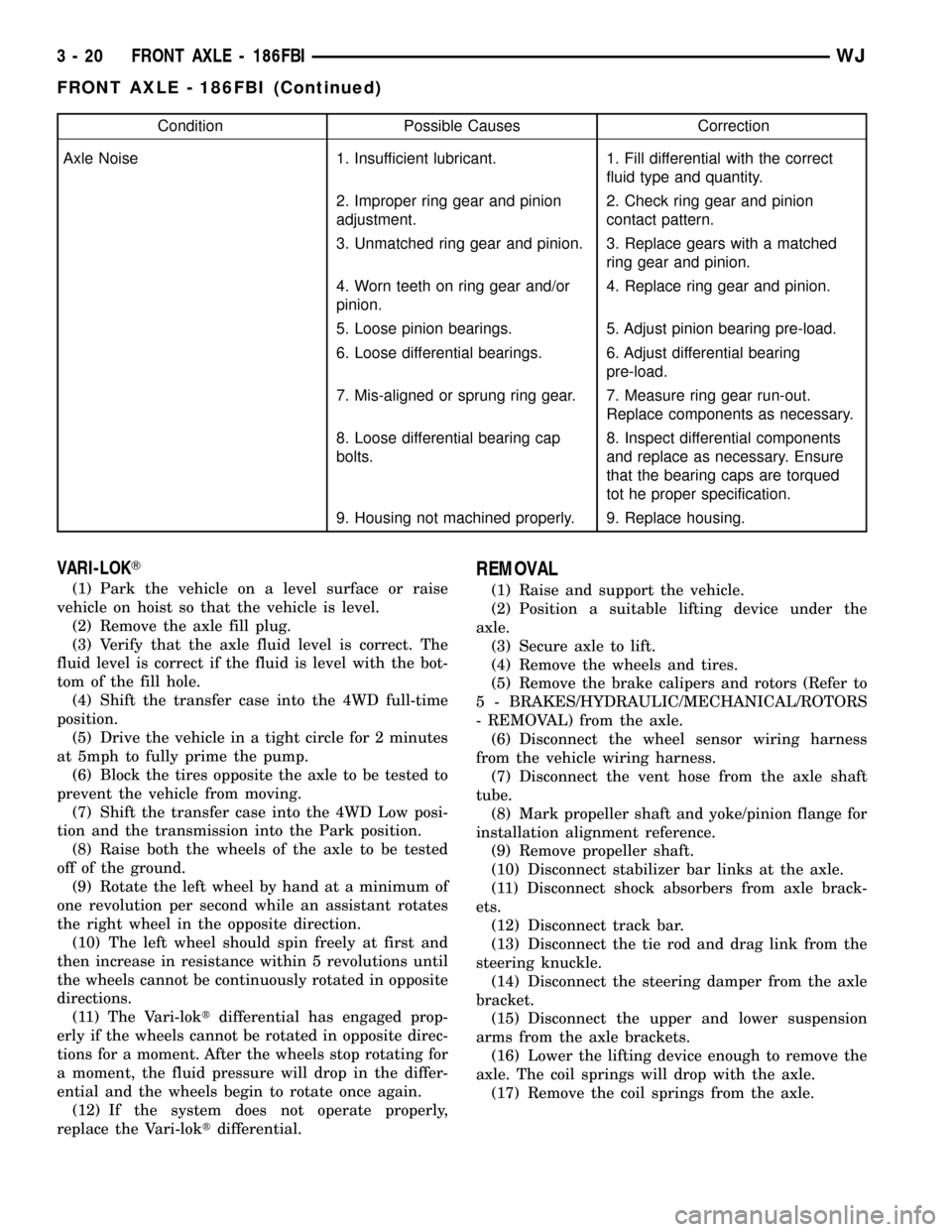
Condition Possible Causes Correction
Axle Noise 1. Insufficient lubricant. 1. Fill differential with the correct
fluid type and quantity.
2. Improper ring gear and pinion
adjustment.2. Check ring gear and pinion
contact pattern.
3. Unmatched ring gear and pinion. 3. Replace gears with a matched
ring gear and pinion.
4. Worn teeth on ring gear and/or
pinion.4. Replace ring gear and pinion.
5. Loose pinion bearings. 5. Adjust pinion bearing pre-load.
6. Loose differential bearings. 6. Adjust differential bearing
pre-load.
7. Mis-aligned or sprung ring gear. 7. Measure ring gear run-out.
Replace components as necessary.
8. Loose differential bearing cap
bolts.8. Inspect differential components
and replace as necessary. Ensure
that the bearing caps are torqued
tot he proper specification.
9. Housing not machined properly. 9. Replace housing.
VARI-LOKT
(1) Park the vehicle on a level surface or raise
vehicle on hoist so that the vehicle is level.
(2) Remove the axle fill plug.
(3) Verify that the axle fluid level is correct. The
fluid level is correct if the fluid is level with the bot-
tom of the fill hole.
(4) Shift the transfer case into the 4WD full-time
position.
(5) Drive the vehicle in a tight circle for 2 minutes
at 5mph to fully prime the pump.
(6) Block the tires opposite the axle to be tested to
prevent the vehicle from moving.
(7) Shift the transfer case into the 4WD Low posi-
tion and the transmission into the Park position.
(8) Raise both the wheels of the axle to be tested
off of the ground.
(9) Rotate the left wheel by hand at a minimum of
one revolution per second while an assistant rotates
the right wheel in the opposite direction.
(10) The left wheel should spin freely at first and
then increase in resistance within 5 revolutions until
the wheels cannot be continuously rotated in opposite
directions.
(11) The Vari-loktdifferential has engaged prop-
erly if the wheels cannot be rotated in opposite direc-
tions for a moment. After the wheels stop rotating for
a moment, the fluid pressure will drop in the differ-
ential and the wheels begin to rotate once again.
(12) If the system does not operate properly,
replace the Vari-loktdifferential.
REMOVAL
(1) Raise and support the vehicle.
(2) Position a suitable lifting device under the
axle.
(3) Secure axle to lift.
(4) Remove the wheels and tires.
(5) Remove the brake calipers and rotors (Refer to
5 - BRAKES/HYDRAULIC/MECHANICAL/ROTORS
- REMOVAL) from the axle.
(6) Disconnect the wheel sensor wiring harness
from the vehicle wiring harness.
(7) Disconnect the vent hose from the axle shaft
tube.
(8) Mark propeller shaft and yoke/pinion flange for
installation alignment reference.
(9) Remove propeller shaft.
(10) Disconnect stabilizer bar links at the axle.
(11) Disconnect shock absorbers from axle brack-
ets.
(12) Disconnect track bar.
(13) Disconnect the tie rod and drag link from the
steering knuckle.
(14) Disconnect the steering damper from the axle
bracket.
(15) Disconnect the upper and lower suspension
arms from the axle brackets.
(16) Lower the lifting device enough to remove the
axle. The coil springs will drop with the axle.
(17) Remove the coil springs from the axle.
3 - 20 FRONT AXLE - 186FBIWJ
FRONT AXLE - 186FBI (Continued)
Page 67 of 2199
If a new gear set is being installed, note the depth
variance etched into both the original and replace-
ment pinion. Add or subtract this number from the
thickness of the original depth shim/oil slinger to
compensate for the difference in the depth variances.
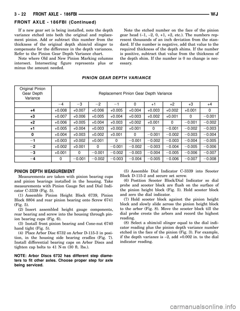
Refer to the Pinion Gear Depth Variance chart.
Note where Old and New Pinion Marking columns
intersect. Intersecting figure represents plus or
minus the amount needed.Note the etched number on the face of the pinion
gear head (±1, ±2, 0, +1, +2, etc.). The numbers rep-
resent thousands of an inch deviation from the stan-
dard. If the number is negative, add that value to the
required thickness of the depth shims. If the number
is positive, subtract that value from the thickness of
the depth shim. If the number is 0 no change is nec-
essary.
PINION GEAR DEPTH VARIANCE
Original Pinion
Gear Depth
VarianceReplacement Pinion Gear Depth Variance
24232221 0 +1 +2 +3 +4
+4+0.008 +0.007 +0.006 +0.005 +0.004 +0.003 +0.002 +0.001 0
+3+0.007 +0.006 +0.005 +0.004 +0.003 +0.002 +0.001 020.001
+2+0.006 +0.005 +0.004 +0.003 +0.002 +0.001 020.00120.002
+1+0.005 +0.004 +0.003 +0.002 +0.001 020.00120.00220.003
0+0.004 +0.003 +0.002 +0.001 020.00120.00220.00320.004
21+0.003 +0.002 +0.001 020.00120.00220.00320.00420.005
22+0.002 +0.001 020.00120.00220.00320.00420.00520.006
23+0.001 020.00120.00220.00320.00420.00520.00620.007
24020.00120.00220.00320.00420.00520.00620.00720.008
PINION DEPTH MEASUREMENT
Measurements are taken with pinion bearing cups
and pinion bearings installed in the housing. Take
measurements with Pinion Gauge Set and Dial Indi-
cator C-3339 (Fig. 5).
(1) Assemble Pinion Height Block 6739, Pinion
Block 8804 and rear pinion bearing onto Screw 6741
(Fig. 5).
(2) Insert assembled height gauge components,
rear bearing and screw into the housing through pin-
ion bearing cups (Fig. 6).
(3) Install front pinion bearing and Cone-nut 6740
hand tight (Fig. 5).
(4) Place Arbor Disc 6732 on Arbor D-115-3 in posi-
tion, in the housing side bearing cradles (Fig. 7).
Install differential bearing caps on Arbor Discs and
tighten cap bolts to 41 N´m (30 ft. lbs.).
NOTE: Arbor Discs 6732 has different step diame-
ters to fit other axles. Choose proper step for axle
being serviced.(5) Assemble Dial Indicator C-3339 into Scooter
Block D-115-2 and secure set screw.
(6) Posttion Scooter Block/Dial Indicator so dial
probe and scooter block are flush on the surface of
the pinion height block (Fig. 5). Hold scooter block
and zero the dial indicator.
(7) Hold scooter block against the pinion height
block and slowly slide across the pinion height block
to the arbor (Fig. 8). Move the scooter block till the
dial probe crests the arbors and record the highest
reading.
(8) Select a shim/oil slinger equal to the dial indi-
cator reading plus the pinion depth variance number
etched in the face of the pinion (Fig. 3). For example,
if the depth variance is ±2, add +0.002 in. to the dial
indicator reading.
3 - 22 FRONT AXLE - 186FBIWJ
FRONT AXLE - 186FBI (Continued)
Page 100 of 2199
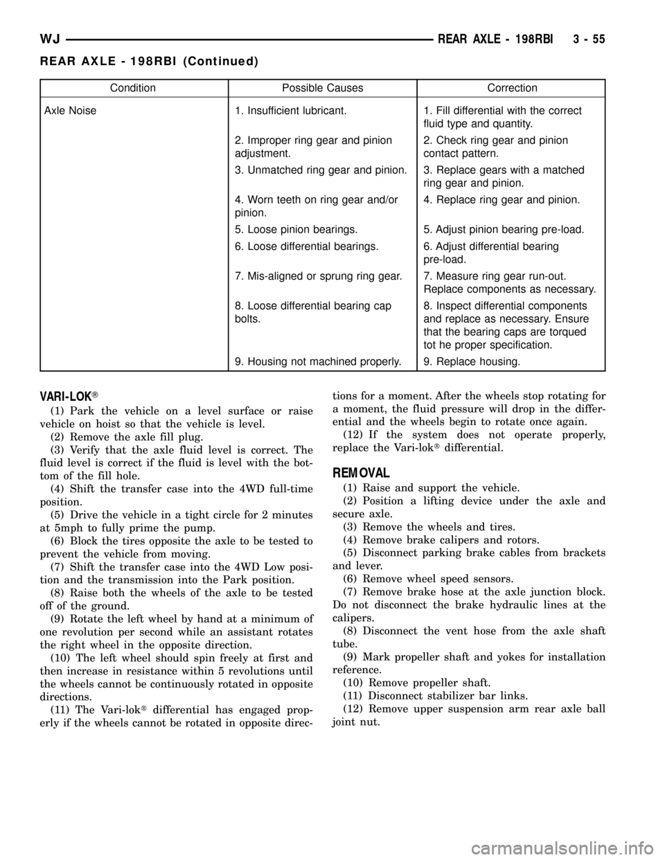
Condition Possible Causes Correction
Axle Noise 1. Insufficient lubricant. 1. Fill differential with the correct
fluid type and quantity.
2. Improper ring gear and pinion
adjustment.2. Check ring gear and pinion
contact pattern.
3. Unmatched ring gear and pinion. 3. Replace gears with a matched
ring gear and pinion.
4. Worn teeth on ring gear and/or
pinion.4. Replace ring gear and pinion.
5. Loose pinion bearings. 5. Adjust pinion bearing pre-load.
6. Loose differential bearings. 6. Adjust differential bearing
pre-load.
7. Mis-aligned or sprung ring gear. 7. Measure ring gear run-out.
Replace components as necessary.
8. Loose differential bearing cap
bolts.8. Inspect differential components
and replace as necessary. Ensure
that the bearing caps are torqued
tot he proper specification.
9. Housing not machined properly. 9. Replace housing.
VARI-LOKT
(1) Park the vehicle on a level surface or raise
vehicle on hoist so that the vehicle is level.
(2) Remove the axle fill plug.
(3) Verify that the axle fluid level is correct. The
fluid level is correct if the fluid is level with the bot-
tom of the fill hole.
(4) Shift the transfer case into the 4WD full-time
position.
(5) Drive the vehicle in a tight circle for 2 minutes
at 5mph to fully prime the pump.
(6) Block the tires opposite the axle to be tested to
prevent the vehicle from moving.
(7) Shift the transfer case into the 4WD Low posi-
tion and the transmission into the Park position.
(8) Raise both the wheels of the axle to be tested
off of the ground.
(9) Rotate the left wheel by hand at a minimum of
one revolution per second while an assistant rotates
the right wheel in the opposite direction.
(10) The left wheel should spin freely at first and
then increase in resistance within 5 revolutions until
the wheels cannot be continuously rotated in opposite
directions.
(11) The Vari-loktdifferential has engaged prop-
erly if the wheels cannot be rotated in opposite direc-tions for a moment. After the wheels stop rotating for
a moment, the fluid pressure will drop in the differ-
ential and the wheels begin to rotate once again.
(12) If the system does not operate properly,
replace the Vari-loktdifferential.
REMOVAL
(1) Raise and support the vehicle.
(2) Position a lifting device under the axle and
secure axle.
(3) Remove the wheels and tires.
(4) Remove brake calipers and rotors.
(5) Disconnect parking brake cables from brackets
and lever.
(6) Remove wheel speed sensors.
(7) Remove brake hose at the axle junction block.
Do not disconnect the brake hydraulic lines at the
calipers.
(8) Disconnect the vent hose from the axle shaft
tube.
(9) Mark propeller shaft and yokes for installation
reference.
(10) Remove propeller shaft.
(11) Disconnect stabilizer bar links.
(12) Remove upper suspension arm rear axle ball
joint nut.
WJREAR AXLE - 198RBI 3 - 55
REAR AXLE - 198RBI (Continued)