Fuel injection JEEP GRAND CHEROKEE 2002 WJ / 2.G User Guide
[x] Cancel search | Manufacturer: JEEP, Model Year: 2002, Model line: GRAND CHEROKEE, Model: JEEP GRAND CHEROKEE 2002 WJ / 2.GPages: 2199, PDF Size: 76.01 MB
Page 1420 of 2199
FUEL SYSTEM
TABLE OF CONTENTS
page page
FUEL DELIVERY..........................1FUEL INJECTION........................31
FUEL DELIVERY
TABLE OF CONTENTS
page page
FUEL DELIVERY
DESCRIPTION..........................2
OPERATION............................2
DIAGNOSIS AND TESTING
FUEL PRESSURE LEAK DOWN TEST......2
STANDARD PROCEDURE - FUEL SYSTEM
PRESSURE RELEASE...................4
SPECIFICATIONS
FUEL SYSTEM PRESSURE..............4
TORQUE - FUEL DELIVERY..............4
SPECIAL TOOLS
FUEL SYSTEM........................5
FUEL FILTER/PRESSURE REGULATOR
DESCRIPTION..........................5
OPERATION............................5
REMOVAL.............................6
INSTALLATION..........................6
FUEL LEVEL SENDING UNIT / SENSOR
DESCRIPTION..........................7
OPERATION............................7
DIAGNOSIS AND TESTING - FUEL LEVEL
SENDING UNIT........................7
REMOVAL.............................7
INSTALLATION..........................8
FUEL LINES
DESCRIPTION..........................8
FUEL PUMP
DESCRIPTION..........................8
OPERATION............................9
DIAGNOSIS AND TESTING
DIAGNOSIS AND TESTING - FUEL PUMP
CAPACITY TEST.......................9
DIAGNOSIS AND TESTING - FUEL PUMP
AMPERAGE TEST......................9FUEL PUMP PRESSURE TEST...........11
FUEL PUMP MODULE
DESCRIPTION.........................13
OPERATION...........................13
REMOVAL.............................13
INSTALLATION.........................14
FUEL RAIL
DESCRIPTION
DESCRIPTION - 4.7L...................15
DESCRIPTION - 4.0L...................15
OPERATION
OPERATION - 4.7L....................15
OPERATION - 4.0L....................15
REMOVAL
REMOVAL - 4.7L......................15
REMOVAL - 4.0L......................17
INSTALLATION
INSTALLATION - 4.7L..................18
INSTALLATION - 4.0L..................18
FUEL TANK
DESCRIPTION.........................19
OPERATION...........................19
REMOVAL.............................19
INSTALLATION.........................20
INLET FILTER
REMOVAL.............................27
INSTALLATION.........................27
QUICK CONNECT FITTING
DESCRIPTION.........................27
STANDARD PROCEDURE - QUICK-CONNECT
FITTINGS...........................27
WJFUEL SYSTEM 14 - 1
Page 1435 of 2199
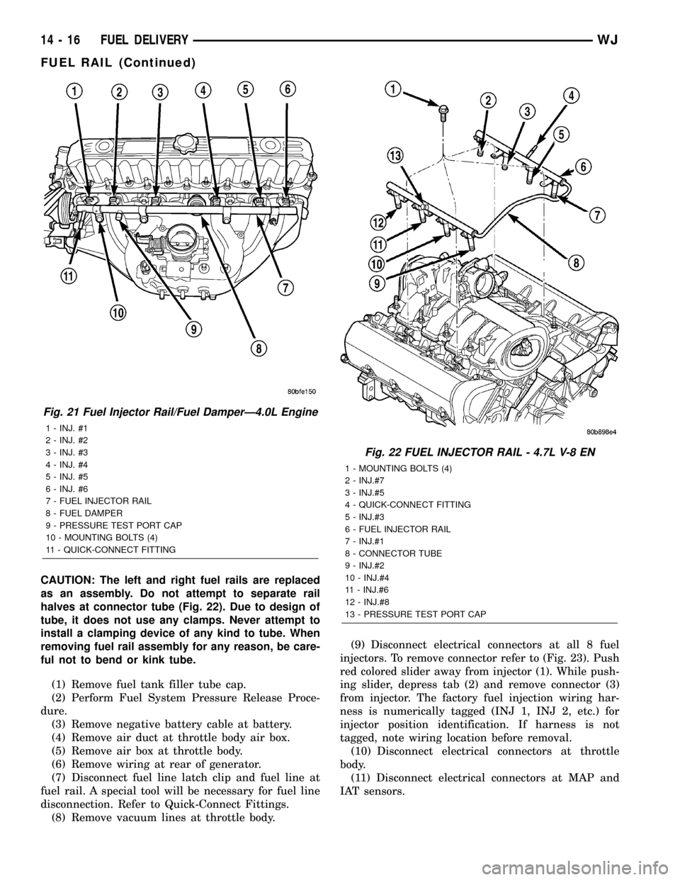
CAUTION: The left and right fuel rails are replaced
as an assembly. Do not attempt to separate rail
halves at connector tube (Fig. 22). Due to design of
tube, it does not use any clamps. Never attempt to
install a clamping device of any kind to tube. When
removing fuel rail assembly for any reason, be care-
ful not to bend or kink tube.
(1) Remove fuel tank filler tube cap.
(2) Perform Fuel System Pressure Release Proce-
dure.
(3) Remove negative battery cable at battery.
(4) Remove air duct at throttle body air box.
(5) Remove air box at throttle body.
(6) Remove wiring at rear of generator.
(7) Disconnect fuel line latch clip and fuel line at
fuel rail. A special tool will be necessary for fuel line
disconnection. Refer to Quick-Connect Fittings.
(8) Remove vacuum lines at throttle body.(9) Disconnect electrical connectors at all 8 fuel
injectors. To remove connector refer to (Fig. 23). Push
red colored slider away from injector (1). While push-
ing slider, depress tab (2) and remove connector (3)
from injector. The factory fuel injection wiring har-
ness is numerically tagged (INJ 1, INJ 2, etc.) for
injector position identification. If harness is not
tagged, note wiring location before removal.
(10) Disconnect electrical connectors at throttle
body.
(11) Disconnect electrical connectors at MAP and
IAT sensors.
Fig. 21 Fuel Injector Rail/Fuel DamperÐ4.0L Engine
1 - INJ. #1
2 - INJ. #2
3 - INJ. #3
4 - INJ. #4
5 - INJ. #5
6 - INJ. #6
7 - FUEL INJECTOR RAIL
8 - FUEL DAMPER
9 - PRESSURE TEST PORT CAP
10 - MOUNTING BOLTS (4)
11 - QUICK-CONNECT FITTING
Fig. 22 FUEL INJECTOR RAIL - 4.7L V-8 EN
1 - MOUNTING BOLTS (4)
2 - INJ.#7
3 - INJ.#5
4 - QUICK-CONNECT FITTING
5 - INJ.#3
6 - FUEL INJECTOR RAIL
7 - INJ.#1
8 - CONNECTOR TUBE
9 - INJ.#2
10 - INJ.#4
11 - INJ.#6
12 - INJ.#8
13 - PRESSURE TEST PORT CAP
14 - 16 FUEL DELIVERYWJ
FUEL RAIL (Continued)
Page 1436 of 2199
(12) Remove first three ignition coils on each bank
(cylinders #1, 3, 5, 2, 4 and 6). Refer to Ignition Coil
Removal/Installation.
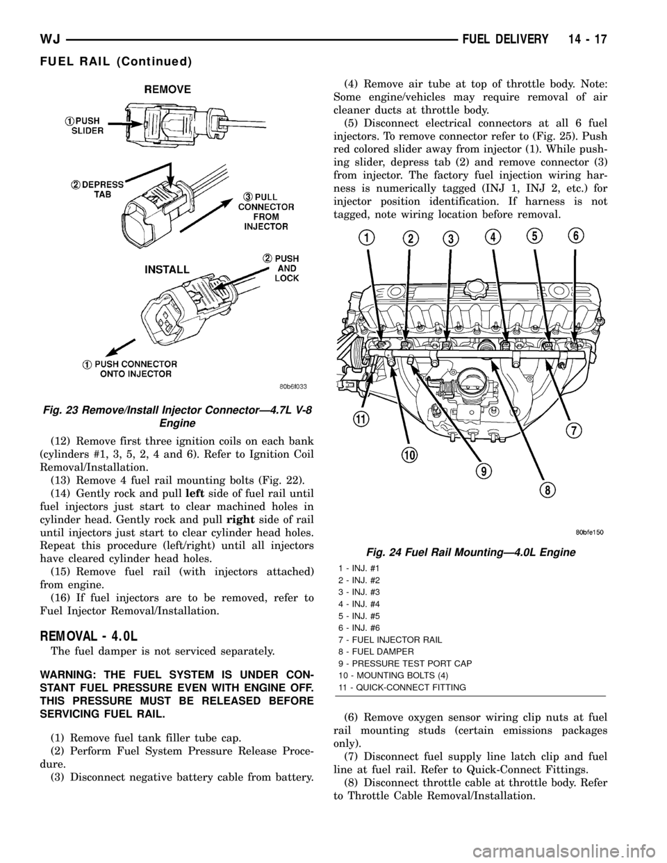
(13) Remove 4 fuel rail mounting bolts (Fig. 22).
(14) Gently rock and pullleftside of fuel rail until
fuel injectors just start to clear machined holes in
cylinder head. Gently rock and pullrightside of rail
until injectors just start to clear cylinder head holes.
Repeat this procedure (left/right) until all injectors
have cleared cylinder head holes.
(15) Remove fuel rail (with injectors attached)
from engine.
(16) If fuel injectors are to be removed, refer to
Fuel Injector Removal/Installation.
REMOVAL - 4.0L
The fuel damper is not serviced separately.
WARNING: THE FUEL SYSTEM IS UNDER CON-
STANT FUEL PRESSURE EVEN WITH ENGINE OFF.
THIS PRESSURE MUST BE RELEASED BEFORE
SERVICING FUEL RAIL.
(1) Remove fuel tank filler tube cap.
(2) Perform Fuel System Pressure Release Proce-
dure.
(3) Disconnect negative battery cable from battery.(4) Remove air tube at top of throttle body. Note:
Some engine/vehicles may require removal of air
cleaner ducts at throttle body.
(5) Disconnect electrical connectors at all 6 fuel
injectors. To remove connector refer to (Fig. 25). Push
red colored slider away from injector (1). While push-
ing slider, depress tab (2) and remove connector (3)
from injector. The factory fuel injection wiring har-
ness is numerically tagged (INJ 1, INJ 2, etc.) for
injector position identification. If harness is not
tagged, note wiring location before removal.
(6) Remove oxygen sensor wiring clip nuts at fuel
rail mounting studs (certain emissions packages
only).
(7) Disconnect fuel supply line latch clip and fuel
line at fuel rail. Refer to Quick-Connect Fittings.
(8) Disconnect throttle cable at throttle body. Refer
to Throttle Cable Removal/Installation.
Fig. 23 Remove/Install Injector ConnectorÐ4.7L V-8
Engine
Fig. 24 Fuel Rail MountingÐ4.0L Engine
1 - INJ. #1
2 - INJ. #2
3 - INJ. #3
4 - INJ. #4
5 - INJ. #5
6 - INJ. #6
7 - FUEL INJECTOR RAIL
8 - FUEL DAMPER
9 - PRESSURE TEST PORT CAP
10 - MOUNTING BOLTS (4)
11 - QUICK-CONNECT FITTING
WJFUEL DELIVERY 14 - 17
FUEL RAIL (Continued)
Page 1450 of 2199
FUEL INJECTION
TABLE OF CONTENTS
page page
FUEL INJECTION
DIAGNOSIS AND TESTING
VISUAL INSPECTION..................32
SPECIFICATIONS
TORQUE - FUEL INJECTION.............39
ACCELERATOR PEDAL
REMOVAL.............................39
INSTALLATION.........................39
CRANKSHAFT POSITION SENSOR
DESCRIPTION
DESCRIPTION - 4.0L...................40
DESCRIPTION - 4.7L...................40
OPERATION
OPERATION - 4.0L....................40
OPERATION - 4.7L....................41
REMOVAL
REMOVAL - 4.0L......................41
REMOVAL - 4.7L......................41
INSTALLATION
INSTALLATION - 4.0L..................42
INSTALLATION - 4.7L..................43
FUEL INJECTOR
DESCRIPTION.........................43
OPERATION
OPERATION.........................43
OPERATION - PCM OUTPUT............43
DIAGNOSIS AND TESTING - FUEL INJECTOR . 44
REMOVAL.............................44
INSTALLATION.........................44
FUEL PUMP RELAY
DESCRIPTION.........................44
OPERATION...........................44
IDLE AIR CONTROL MOTOR
DESCRIPTION.........................44
OPERATION...........................44
REMOVAL
REMOVAL - 4.0L......................45
REMOVAL - 4.7L......................45
INSTALLATION
INSTALLATION - 4.0L..................46
INSTALLATION - 4.7L..................46
INTAKE AIR TEMPERATURE SENSOR
DESCRIPTION.........................46
OPERATION...........................46
REMOVAL
REMOVAL - 4.0L......................46
REMOVAL - 4.7L......................46
INSTALLATION
INSTALLATION - 4.0L..................47INSTALLATION - 4.7L..................47
MAP SENSOR
DESCRIPTION
DESCRIPTION........................48
DESCRIPTION - 4.7L...................48
OPERATION...........................48
REMOVAL
REMOVAL - 4.0L......................48
REMOVAL - 4.7L......................49
INSTALLATION
INSTALLATION - 4.0L..................49
INSTALLATION - 4.7L..................49
O2S HEATER RELAY
DESCRIPTION.........................49
OPERATION...........................49
REMOVAL.............................50
INSTALLATION.........................50
O2S SENSOR
DESCRIPTION.........................50
OPERATION...........................50
REMOVAL.............................51
INSTALLATION.........................51
THROTTLE BODY
DESCRIPTION.........................52
OPERATION...........................52
REMOVAL
REMOVAL - 4.0L......................52
REMOVAL - 4.7L......................53
INSTALLATION
INSTALLATION - 4.0L..................53
INSTALLATION - 4.7L..................54
THROTTLE CONTROL CABLE
REMOVAL
REMOVAL - 4.0L......................54
REMOVAL - 4.7L......................55
INSTALLATION
INSTALLATION ± 4.0L..................55
INSTALLATION - 4.7L..................56
THROTTLE POSITION SENSOR
DESCRIPTION.........................56
OPERATION...........................56
REMOVAL
REMOVAL - 4.0L......................57
REMOVAL - 4.7L......................57
INSTALLATION
INSTALLATION - 4.0L..................58
INSTALLATION - 4.7L..................58
WJFUEL INJECTION 14 - 31
Page 1451 of 2199
FUEL INJECTION
DIAGNOSIS AND TESTING
VISUAL INSPECTION
A visual inspection for loose, disconnected or incor-
rectly routed wires, vacuum lines and hoses should
be made. This should be done before attempting to
diagnose or service the fuel injection system. A visual
check will help spot these faults and save unneces-
sary test and diagnostic time. A thorough visual
inspection will include the following checks:
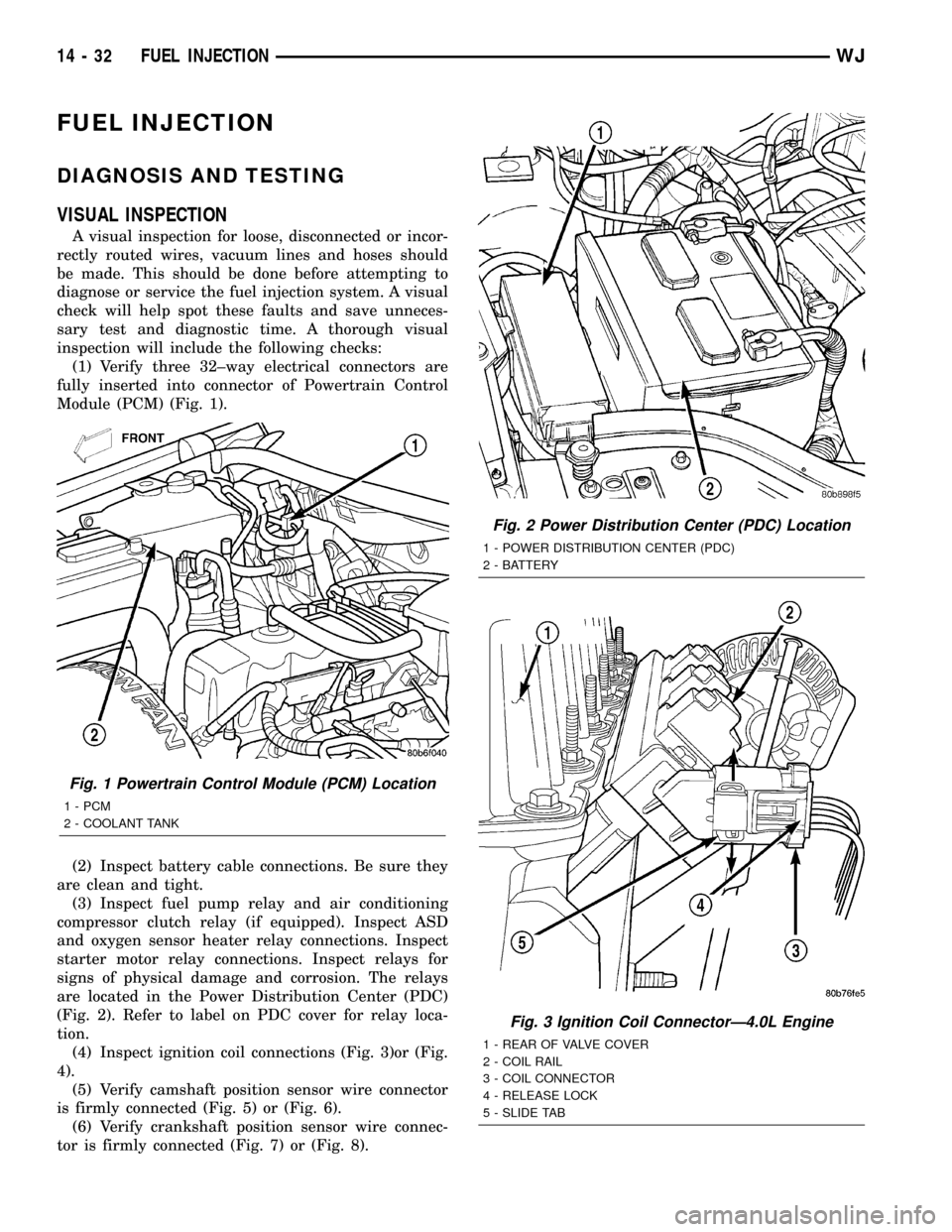
(1) Verify three 32±way electrical connectors are
fully inserted into connector of Powertrain Control
Module (PCM) (Fig. 1).
(2) Inspect battery cable connections. Be sure they
are clean and tight.
(3) Inspect fuel pump relay and air conditioning
compressor clutch relay (if equipped). Inspect ASD
and oxygen sensor heater relay connections. Inspect
starter motor relay connections. Inspect relays for
signs of physical damage and corrosion. The relays
are located in the Power Distribution Center (PDC)
(Fig. 2). Refer to label on PDC cover for relay loca-
tion.
(4) Inspect ignition coil connections (Fig. 3)or (Fig.
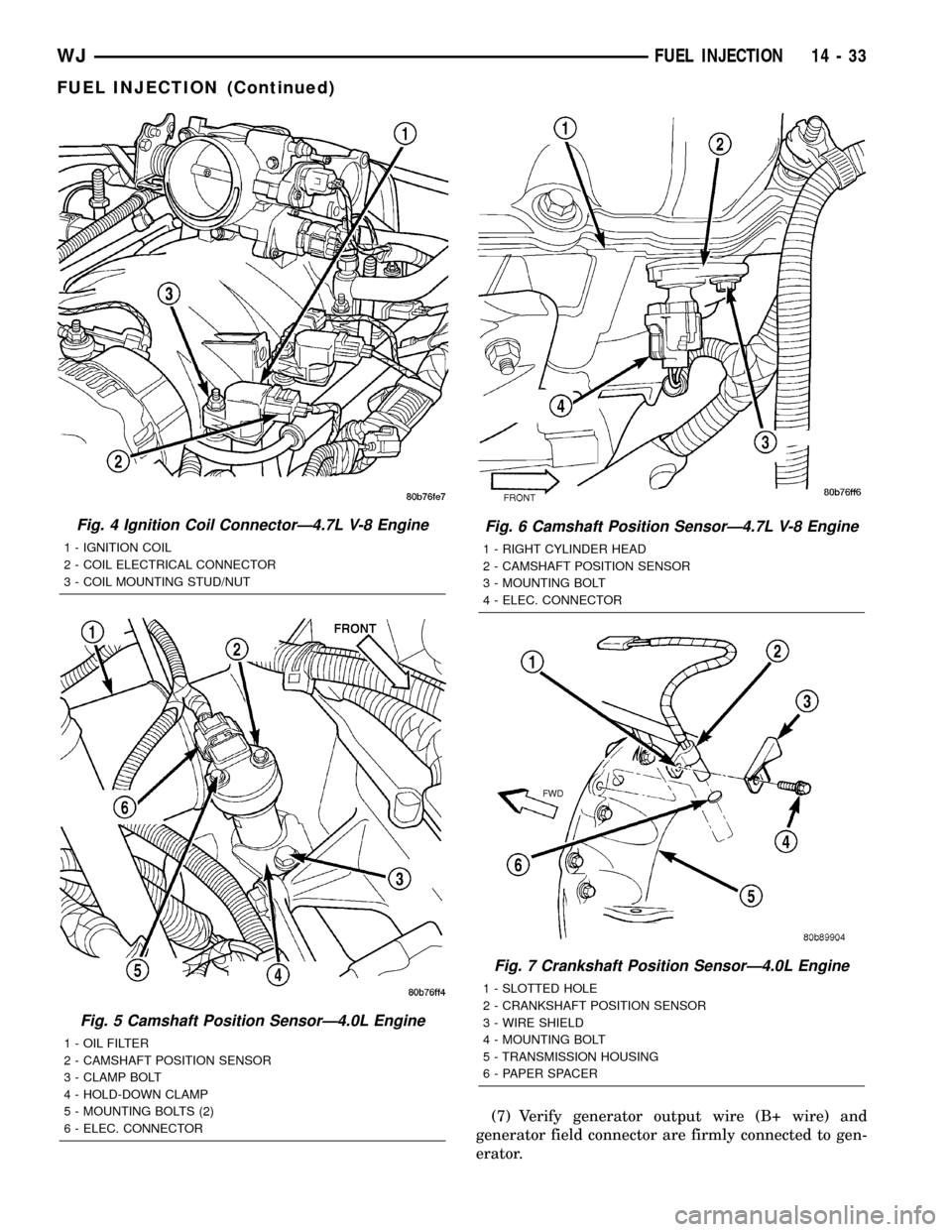
4).
(5) Verify camshaft position sensor wire connector
is firmly connected (Fig. 5) or (Fig. 6).
(6) Verify crankshaft position sensor wire connec-
tor is firmly connected (Fig. 7) or (Fig. 8).
Fig. 1 Powertrain Control Module (PCM) Location
1 - PCM
2 - COOLANT TANK
Fig. 2 Power Distribution Center (PDC) Location
1 - POWER DISTRIBUTION CENTER (PDC)
2 - BATTERY
Fig. 3 Ignition Coil ConnectorÐ4.0L Engine
1 - REAR OF VALVE COVER
2 - COIL RAIL
3 - COIL CONNECTOR
4 - RELEASE LOCK
5 - SLIDE TAB
14 - 32 FUEL INJECTIONWJ
Page 1452 of 2199
(7) Verify generator output wire (B+ wire) and
generator field connector are firmly connected to gen-
erator.
Fig. 4 Ignition Coil ConnectorÐ4.7L V-8 Engine
1 - IGNITION COIL
2 - COIL ELECTRICAL CONNECTOR
3 - COIL MOUNTING STUD/NUT
Fig. 5 Camshaft Position SensorÐ4.0L Engine
1 - OIL FILTER
2 - CAMSHAFT POSITION SENSOR
3 - CLAMP BOLT
4 - HOLD-DOWN CLAMP
5 - MOUNTING BOLTS (2)
6 - ELEC. CONNECTOR
Fig. 6 Camshaft Position SensorÐ4.7L V-8 Engine
1 - RIGHT CYLINDER HEAD
2 - CAMSHAFT POSITION SENSOR
3 - MOUNTING BOLT
4 - ELEC. CONNECTOR
Fig. 7 Crankshaft Position SensorÐ4.0L Engine
1 - SLOTTED HOLE
2 - CRANKSHAFT POSITION SENSOR
3 - WIRE SHIELD
4 - MOUNTING BOLT
5 - TRANSMISSION HOUSING
6 - PAPER SPACER
WJFUEL INJECTION 14 - 33
FUEL INJECTION (Continued)
Page 1453 of 2199
(8) Inspect system body grounds for loose or dirty
connections. Refer to Group 8, Wiring for ground
locations.
(9) Verify crankcase ventilation (CCV) operation.
Refer to Emission Control System for additional
information.
(10) Inspect all fuel line quick-connect fittings for
damage or leaks.
(11) Verify hose connections to all ports of vacuum
fittings on intake manifold, and for emission system
are tight and not leaking.
(12) Inspect accelerator cable, transmission throt-
tle cable (if equipped) and speed control cable connec-
tions (if equipped). Check their connections to
throttle body linkage for any binding or restrictions.
(13) Verify vacuum booster hose is firmly con-
nected to fitting on intake manifold. Also check con-
nection to brake vacuum booster.(14) Inspect air cleaner inlet and air cleaner ele-
ment for dirt or restrictions.
(15) Inspect radiator grille area, radiator fins and
air conditioning condenser for restrictions.
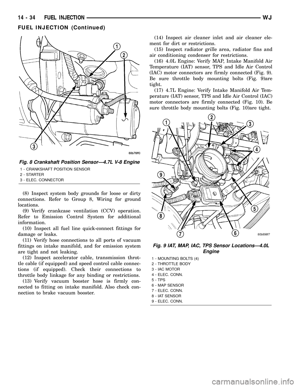
(16) 4.0L Engine: Verify MAP, Intake Manifold Air
Temperature (IAT) sensor, TPS and Idle Air Control
(IAC) motor connectors are firmly connected (Fig. 9).
Be sure throttle body mounting bolts (Fig. 9)are
tight.
(17) 4.7L Engine: Verify Intake Manifold Air Tem-
perature (IAT) sensor, TPS and Idle Air Control (IAC)
motor connectors are firmly connected (Fig. 10). Be
sure throttle body mounting bolts (Fig. 10)are tight.
Fig. 8 Crankshaft Position SensorÐ4.7L V-8 Engine
1 - CRANKSHAFT POSITION SENSOR
2-STARTER
3 - ELEC. CONNECTOR
Fig. 9 IAT, MAP, IAC, TPS Sensor LocationsÐ4.0L
Engine
1 - MOUNTING BOLTS (4)
2 - THROTTLE BODY
3 - IAC MOTOR
4 - ELEC. CONN.
5 - TPS
6 - MAP SENSOR
7 - ELEC. CONN.
8 - IAT SENSOR
9 - ELEC. CONN.
14 - 34 FUEL INJECTIONWJ
FUEL INJECTION (Continued)
Page 1454 of 2199
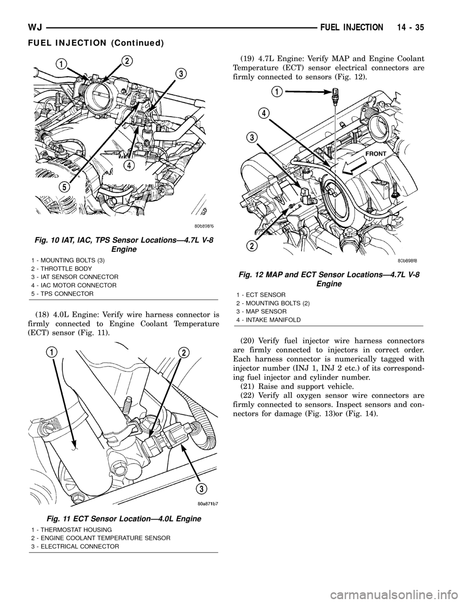
(18) 4.0L Engine: Verify wire harness connector is
firmly connected to Engine Coolant Temperature
(ECT) sensor (Fig. 11).(19) 4.7L Engine: Verify MAP and Engine Coolant
Temperature (ECT) sensor electrical connectors are
firmly connected to sensors (Fig. 12).
(20) Verify fuel injector wire harness connectors
are firmly connected to injectors in correct order.
Each harness connector is numerically tagged with
injector number (INJ 1, INJ 2 etc.) of its correspond-
ing fuel injector and cylinder number.
(21) Raise and support vehicle.
(22) Verify all oxygen sensor wire connectors are
firmly connected to sensors. Inspect sensors and con-
nectors for damage (Fig. 13)or (Fig. 14).
Fig. 10 IAT, IAC, TPS Sensor LocationsÐ4.7L V-8
Engine
1 - MOUNTING BOLTS (3)
2 - THROTTLE BODY
3 - IAT SENSOR CONNECTOR
4 - IAC MOTOR CONNECTOR
5 - TPS CONNECTOR
Fig. 11 ECT Sensor LocationÐ4.0L Engine
1 - THERMOSTAT HOUSING
2 - ENGINE COOLANT TEMPERATURE SENSOR
3 - ELECTRICAL CONNECTOR
Fig. 12 MAP and ECT Sensor LocationsÐ4.7L V-8
Engine
1 - ECT SENSOR
2 - MOUNTING BOLTS (2)
3 - MAP SENSOR
4 - INTAKE MANIFOLD
WJFUEL INJECTION 14 - 35
FUEL INJECTION (Continued)
Page 1455 of 2199
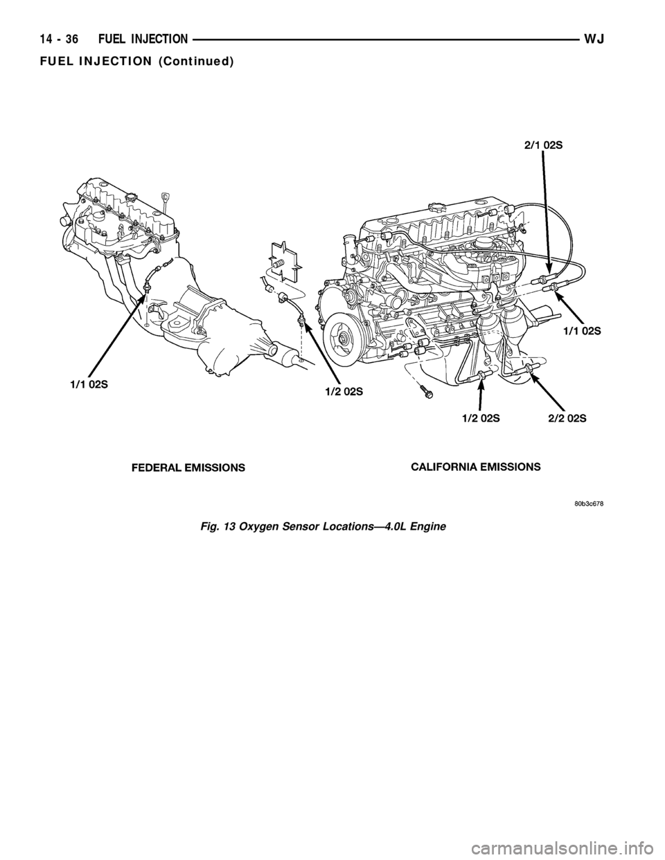
Fig. 13 Oxygen Sensor LocationsÐ4.0L Engine
14 - 36 FUEL INJECTIONWJ
FUEL INJECTION (Continued)
Page 1456 of 2199
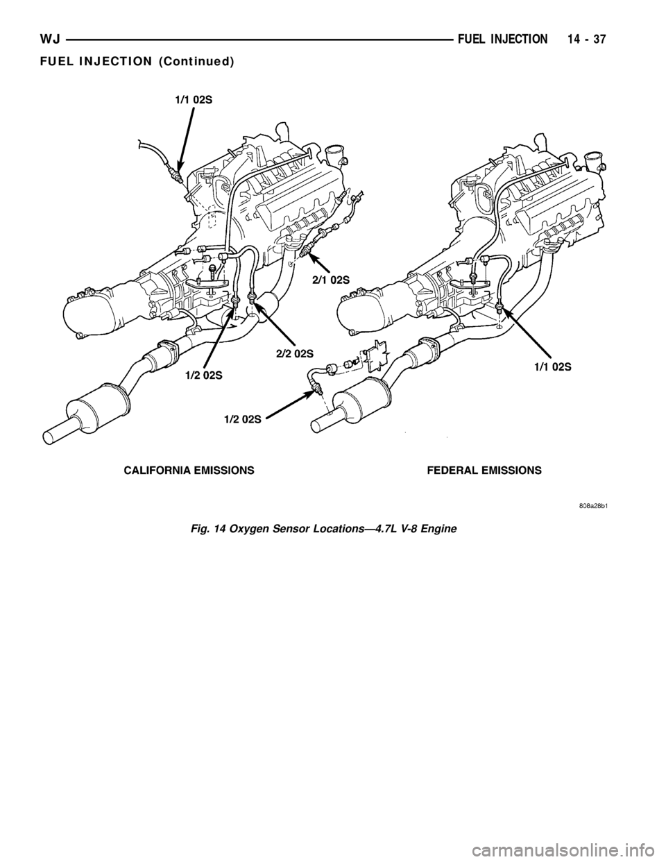
Fig. 14 Oxygen Sensor LocationsÐ4.7L V-8 Engine
WJFUEL INJECTION 14 - 37
FUEL INJECTION (Continued)