Serpentine JEEP GRAND CHEROKEE 2002 WJ / 2.G User Guide
[x] Cancel search | Manufacturer: JEEP, Model Year: 2002, Model line: GRAND CHEROKEE, Model: JEEP GRAND CHEROKEE 2002 WJ / 2.GPages: 2199, PDF Size: 76.01 MB
Page 273 of 2199
CAUTION: When installing the serpentine accessory
drive belt, belt must be routed correctly. If not,
engine may overheat due to water pump rotating in
wrong direction.
(6) Refill cooling system (Refer to 7 - COOLING -
STANDARD PROCEDURE).
(7) Connect negative battery cable.
(8) Start and warm the engine. Check for leaks.
WATER PUMP - 4.0L
DESCRIPTION
CAUTION: All 4.0L 6-cylinder engines are equipped
with a reverse (counterclockwise) rotating water
pump and thermal viscous fan drive assembly.
REVERSE is stamped or imprinted on the cover of
the viscous fan drive and inner side of the fan. The
letter R is stamped into the back of the water pump
impeller. Engines from previous model years,
depending upon application, may have been
equipped with a forward (clockwise) rotating water
pump. Installation of the wrong water pump or vis-
cous fan drive will cause engine over heating.
A centrifugal water pump circulates coolant
through the water jackets, passages, intake manifold,
radiator core, cooling system hoses and heater core.
The pump is driven from the engine crankshaft by a
single serpentine drive belt.
The water pump impeller is pressed onto the rear
of a shaft that rotates in bearings pressed into the
housing. The housing has two small holes to allow
seepage to escape. The water pump seals are lubri-
cated by the antifreeze in the coolant mixture. No
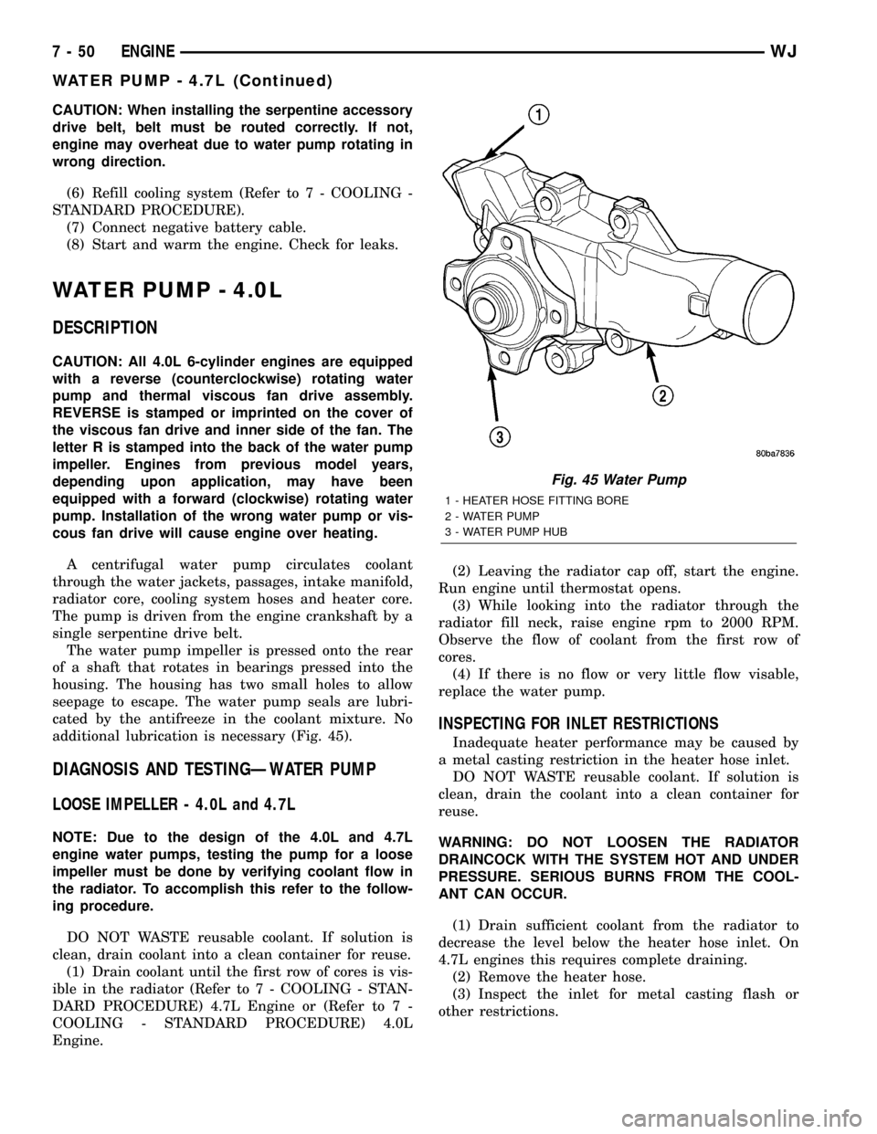
additional lubrication is necessary (Fig. 45).
DIAGNOSIS AND TESTINGÐWATER PUMP
LOOSE IMPELLER - 4.0L and 4.7L
NOTE: Due to the design of the 4.0L and 4.7L
engine water pumps, testing the pump for a loose
impeller must be done by verifying coolant flow in
the radiator. To accomplish this refer to the follow-
ing procedure.
DO NOT WASTE reusable coolant. If solution is
clean, drain coolant into a clean container for reuse.
(1) Drain coolant until the first row of cores is vis-
ible in the radiator (Refer to 7 - COOLING - STAN-
DARD PROCEDURE) 4.7L Engine or (Refer to 7 -
COOLING - STANDARD PROCEDURE) 4.0L
Engine.(2) Leaving the radiator cap off, start the engine.
Run engine until thermostat opens.
(3) While looking into the radiator through the
radiator fill neck, raise engine rpm to 2000 RPM.
Observe the flow of coolant from the first row of
cores.
(4) If there is no flow or very little flow visable,
replace the water pump.
INSPECTING FOR INLET RESTRICTIONS
Inadequate heater performance may be caused by
a metal casting restriction in the heater hose inlet.
DO NOT WASTE reusable coolant. If solution is
clean, drain the coolant into a clean container for
reuse.
WARNING: DO NOT LOOSEN THE RADIATOR
DRAINCOCK WITH THE SYSTEM HOT AND UNDER
PRESSURE. SERIOUS BURNS FROM THE COOL-
ANT CAN OCCUR.
(1) Drain sufficient coolant from the radiator to
decrease the level below the heater hose inlet. On
4.7L engines this requires complete draining.
(2) Remove the heater hose.
(3) Inspect the inlet for metal casting flash or
other restrictions.
Fig. 45 Water Pump
1 - HEATER HOSE FITTING BORE
2 - WATER PUMP
3 - WATER PUMP HUB
7 - 50 ENGINEWJ
WATER PUMP - 4.7L (Continued)
Page 276 of 2199
CAUTION: When installing the serpentine engine
accessory drive belt, the belt MUST be routed cor-
rectly. If not, the engine may overheat due to the
water pump rotating in the wrong direction. Refer to
the Belt Removal and Installtion in this group for
appropriate belt routing. You may also refer to the
Belt Routing Label in the vehicle engine compart-
ment.
Install accessory drive belt (Refer to 7 - COOLING/
ACCESSORY DRIVE/DRIVE BELTS - INSTALLA-
TION).
(6) Install fan blade and viscous fan drive onto
water pump.
(7) Fill cooling system with coolant and check for
leaks. (Refer to 7 - COOLING - STANDARD PROCE-
DURE).
(8) Connect battery cable to battery.
(9) Start and warm the engine. Check for leaks.
RADIATOR PRESSURE CAP
DESCRIPTION
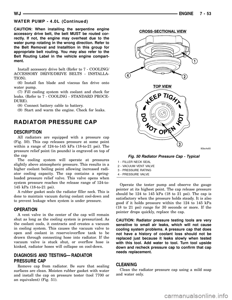
All radiators are equipped with a pressure cap
(Fig. 50). This cap releases pressure at some point
within a range of 124-to-145 kPa (18-to-21 psi). The
pressure relief point (in pounds) is engraved on top of
the cap
The cooling system will operate at pressures
slightly above atmospheric pressure. This results in a
higher coolant boiling point allowing increased radi-
ator cooling capacity. The cap contains a spring-
loaded pressure relief valve. This valve opens when
system pressure reaches the release range of 124-to-
145 kPa (18-to-21 psi).
A rubber gasket seals the radiator filler neck. This is
done to maintain vacuum during coolant cool-down and
to prevent leakage when system is under pressure.
OPERATION
A vent valve in the center of the cap will remain
shut as long as the cooling system is pressurized. As
the coolant cools, it contracts and creates a vacuum
in cooling system. This causes the vacuum valve to
open and coolant in reserve/overflow tank to be
drawn through connecting hose into radiator. If the
vacuum valve is stuck shut, or overflow hose is
kinked, radiator hoses will collapse on cool-down.
DIAGNOSIS AND TESTINGÐRADIATOR
PRESSURE CAP
Remove cap from radiator. Be sure that sealing
surfaces are clean. Moisten rubber gasket with water
and install the cap on pressure tester (tool 7700 or
an equivalent) (Fig. 51).Operate the tester pump and observe the gauge
pointer at its highest point. The cap release pressure
should be 124 to 145 kPa (18 to 21 psi). The cap is
satisfactory when the pressure holds steady. It is also
good if it holds pressure within the 124 to 145 kPa
(18 to 21 psi) range for 30 seconds or more. If the
pointer drops quickly, replace the cap.
CAUTION: Radiator pressure testing tools are very
sensitive to small air leaks, which will not cause
cooling system problems. A pressure cap that does
not have a history of coolant loss should not be
replaced just because it leaks slowly when tested
with this tool. Add water to tool. Turn tool upside
down and recheck pressure cap to confirm that cap
needs replacement.CLEANING
Clean the radiator pressure cap using a mild soap
and water only.
Fig. 50 Radiator Pressure Cap - Typical
1 - FILLER NECK SEAL
2 - VACUUM VENT VALVE
3 - PRESSURE RATING
4 - PRESSURE VALVE
WJENGINE 7 - 53
WATER PUMP - 4.0L (Continued)
Page 358 of 2199
GENERATOR
DESCRIPTION
The generator is belt-driven by the engine using a
serpentine type drive belt. It is serviced only as a
complete assembly. If the generator fails for any rea-
son, the entire assembly must be replaced.
OPERATION
As the energized rotor begins to rotate within the
generator, the spinning magnetic field induces a cur-
rent into the windings of the stator coil. Once the
generator begins producing sufficient current, it also
provides the current needed to energize the rotor.
The Y type stator winding connections deliver the
induced AC current to 3 positive and 3 negative
diodes for rectification. From the diodes, rectified DC
current is delivered to the vehicle electrical system
through the generator battery terminal.
Although the generators appear the same exter-
nally, different generators with different output rat-
ings are used on this vehicle. Be certain that the
replacement generator has the same output rating
and part number as the original unit. Refer to Gen-
erator Ratings in the Specifications section at the
back of this group for amperage ratings and part
numbers.
Noise emitting from the generator may be caused
by: worn, loose or defective bearings; a loose or defec-
tive drive pulley; incorrect, worn, damaged or misad-
justed fan drive belt; loose mounting bolts; a
misaligned drive pulley or a defective stator or diode.
REMOVAL
WARNING: DISCONNECT NEGATIVE CABLE FROM
BATTERY BEFORE REMOVING BATTERY OUTPUT
WIRE (B+ WIRE) FROM GENERATOR. FAILURE TO
DO SO CAN RESULT IN INJURY OR DAMAGE TO
ELECTRICAL SYSTEM.
(1) Disconnect negative battery cable at battery.
(2) Remove generator drive belt. Refer to Cooling
System for procedure.
(3) Unsnap cable protector cover from B+ mount-
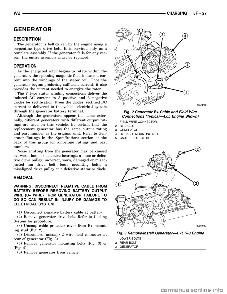
ing stud (Fig. 2) .
(4) Disconnect (unsnap) 2±wire field connector at
rear of generator (Fig. 2) .
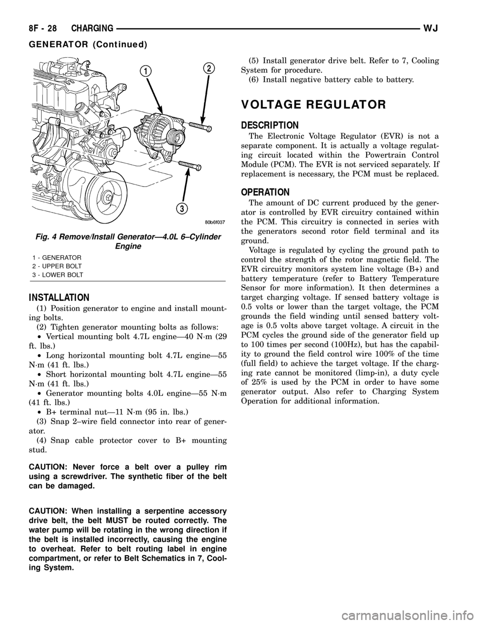
(5) Remove generator mounting bolts (Fig. 3) or
(Fig. 4).
(6) Remove generator from vehicle.
Fig. 2 Generator B+ Cable and Field Wire
Connections (TypicalÐ4.0L Engine Shown)
1 - FIELD WIRE CONNECTOR
2 - B+ CABLE
3 - GENERATOR
4 - B+ CABLE MOUNTING NUT
5 - CABLE PROTECTOR
Fig. 3 Remove/Install GeneratorÐ4.7L V-8 Engine
1 - LOWER BOLTS
2 - REAR BOLT
3 - GENERATOR
WJCHARGING 8F - 27
Page 359 of 2199
INSTALLATION
(1) Position generator to engine and install mount-
ing bolts.
(2) Tighten generator mounting bolts as follows:
²Vertical mounting bolt 4.7L engineÐ40 N´m (29
ft. lbs.)
²Long horizontal mounting bolt 4.7L engineÐ55
N´m (41 ft. lbs.)
²Short horizontal mounting bolt 4.7L engineÐ55
N´m (41 ft. lbs.)
²Generator mounting bolts 4.0L engineÐ55 N´m
(41 ft. lbs.)
²B+ terminal nutÐ11 N´m (95 in. lbs.)
(3) Snap 2±wire field connector into rear of gener-
ator.
(4) Snap cable protector cover to B+ mounting
stud.
CAUTION: Never force a belt over a pulley rim
using a screwdriver. The synthetic fiber of the belt
can be damaged.
CAUTION: When installing a serpentine accessory
drive belt, the belt MUST be routed correctly. The
water pump will be rotating in the wrong direction if
the belt is installed incorrectly, causing the engine
to overheat. Refer to belt routing label in engine
compartment, or refer to Belt Schematics in 7, Cool-
ing System.(5) Install generator drive belt. Refer to 7, Cooling
System for procedure.
(6) Install negative battery cable to battery.
VOLTAGE REGULATOR
DESCRIPTION
The Electronic Voltage Regulator (EVR) is not a
separate component. It is actually a voltage regulat-
ing circuit located within the Powertrain Control
Module (PCM). The EVR is not serviced separately. If
replacement is necessary, the PCM must be replaced.
OPERATION
The amount of DC current produced by the gener-
ator is controlled by EVR circuitry contained within
the PCM. This circuitry is connected in series with
the generators second rotor field terminal and its
ground.
Voltage is regulated by cycling the ground path to
control the strength of the rotor magnetic field. The
EVR circuitry monitors system line voltage (B+) and
battery temperature (refer to Battery Temperature
Sensor for more information). It then determines a
target charging voltage. If sensed battery voltage is
0.5 volts or lower than the target voltage, the PCM
grounds the field winding until sensed battery volt-
age is 0.5 volts above target voltage. A circuit in the
PCM cycles the ground side of the generator field up
to 100 times per second (100Hz), but has the capabil-
ity to ground the field control wire 100% of the time
(full field) to achieve the target voltage. If the charg-
ing rate cannot be monitored (limp-in), a duty cycle
of 25% is used by the PCM in order to have some
generator output. Also refer to Charging System
Operation for additional information.
Fig. 4 Remove/Install GeneratorÐ4.0L 6±Cylinder
Engine
1 - GENERATOR
2 - UPPER BOLT
3 - LOWER BOLT
8F - 28 CHARGINGWJ
GENERATOR (Continued)
Page 1265 of 2199
(12) Install the push rods, rocker arms, pivots and
bridges in the order they were removed (Refer to 9 -
ENGINE/CYLINDER HEAD/ROCKER ARM /
ADJUSTER ASSY - INSTALLATION).
(13) Install the engine cylinder head cover (Refer
to 9 - ENGINE/CYLINDER HEAD/CYLINDER
HEAD COVER(S) - INSTALLATION).
(14) Attach the air conditioner compressor mount-
ing bracket to the engine cylinder head and block.
Tighten the bolts to 40 N´m (30 ft. lbs.) torque.
(15) Attach the air conditioning compressor to the
bracket. Tighten the bolts to 27 N´m (20 ft. lbs.)
torque.
CAUTION: The serpentine drive belt must be routed
correctly. Incorrect routing can cause the water
pump to turn in the opposite direction causing the
engine to overheat.
(16) Install the serpentine drive belt. (Refer to 7 -
COOLING/ACCESSORY DRIVE/DRIVE BELTS -
INSTALLATION).
(17) Install the air cleaner and ducting.
(18) Connect the hoses to the engine thermostat
housing and fill the cooling system to the specified
level (Refer to 7 - COOLING - STANDARD PROCE-
DURE).
(19) The automatic transmission throttle linkage
and cable must be adjusted after completing the
engine cylinder head installation (Refer to 21 -
TRANSMISSION/TRANSAXLE/AUTOMATIC - AW4/
THROTTLE VALVE CABLE - ADJUSTMENTS).
(20) Install the temperature sending unit and con-
nect the wire connector.
(21) If equipped with air conditioning, install A/C
compressor (Refer to 24 - HEATING & AIR CONDI-
TIONING/PLUMBING/A/C COMPRESSOR -
INSTALLATION) and charge A/C system (Refer to 24
- HEATING & AIR CONDITIONING/PLUMBING -
STANDARD PROCEDURE).
(22) Connect negative cable to battery.
WARNING: USE EXTREME CAUTION WHEN THE
ENGINE IS OPERATING. DO NOT STAND IN DIRECT
LINE WITH THE FAN. DO NOT PUT HANDS NEAR
THE PULLEYS, BELTS OR FAN. DO NOT WEAR
LOOSE CLOTHING.
(23) Operate the engine with the radiator cap off.
Inspect for leaks and continue operating the engine
until the engine thermostat opens. Add coolant, if
required.CYLINDER HEAD COVER(S)
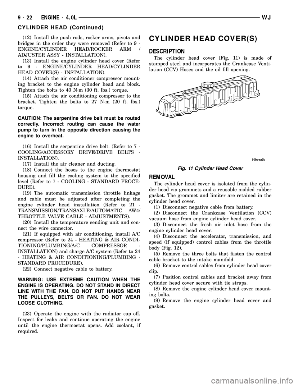
DESCRIPTION
The cylinder head cover (Fig. 11) is made of
stamped steel and incorporates the Crankcase Venti-
lation (CCV) Hoses and the oil fill opening.
REMOVAL
The cylinder head cover is isolated from the cylin-
der head via grommets and a reusable molded rubber
gasket. The grommet and limiter are retained in the
cylinder head cover.
(1) Disconnect negative cable from battery.
(2) Disconnect the Crankcase Ventilation (CCV)
vacuum hose from engine cylinder head cover.
(3) Disconnect the fresh air inlet hose from the
engine cylinder head cover.
(4) Disconnect the accelerator, transmission, and
speed (if equipped) control cables from the throttle
body (Fig. 12).
(5) Remove the three bolts that fasten the control
cable bracket to the intake manifold.
(6) Remove control cables from cylinder head cover
clip.
(7) Position control cables and bracket away from
cylinder head cover secure with tie straps.
(8) Remove the engine cylinder head cover mount-
ing bolts.
(9) Remove the engine cylinder head cover and
gasket.
Fig. 11 Cylinder Head Cover
9 - 22 ENGINE - 4.0LWJ
CYLINDER HEAD (Continued)
Page 1276 of 2199
(16) Install the serpentine drive belt (Refer to 7 -
COOLING/ACCESSORY DRIVE/DRIVE BELTS -
INSTALLATION).
NOTE: During installation, lubricate the hydraulic
valve tappets and all valve components with
MoparTEngine Oil Supplement, or equivalent. TheMoparTEngine Oil Supplement, or equivalent must
remain with the engine oil for at least 1609 km
(1,000 miles). The oil supplement need not be
drained until the next scheduled oil change.
(17) Install the radiator (Refer to 7 - COOLING/
ENGINE/RADIATOR - INSTALLATION).
(18) Check the ignition timing and adjust as nec-
essary.
(19) Install the grille and bumper, if removed.
(20) Connect negative cable to battery.
CONNECTING ROD BEARINGS
STANDARD PROCEDURE - FITTING
CONNECTING ROD BEARINGS
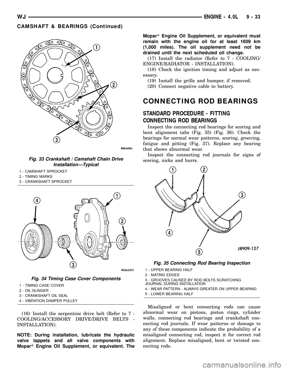
Inspect the connecting rod bearings for scoring and
bent alignment tabs (Fig. 35) (Fig. 36). Check the
bearings for normal wear patterns, scoring, grooving,
fatigue and pitting (Fig. 37). Replace any bearing
that shows abnormal wear.
Inspect the connecting rod journals for signs of
scoring, nicks and burrs.
Misaligned or bent connecting rods can cause
abnormal wear on pistons, piston rings, cylinder
walls, connecting rod bearings and crankshaft con-
necting rod journals. If wear patterns or damage to
any of these components indicate the probability of a
misaligned connecting rod, inspect it for correct rod
alignment. Replace misaligned, bent or twisted con-
necting rods.
Fig. 33 Crankshaft / Camshaft Chain Drive
InstallationÐTypical
1 - CAMSHAFT SPROCKET
2 - TIMING MARKS
3 - CRANKSHAFT SPROCKET
Fig. 34 Timing Case Cover Components
1 - TIMING CASE COVER
2 - OIL SLINGER
3 - CRANKSHAFT OIL SEAL
4 - VIBRATION DAMPER PULLEY
Fig. 35 Connecting Rod Bearing Inspection
1 - UPPER BEARING HALF
2 - MATING EDGES
3 - GROOVES CAUSED BY ROD BOLTS SCRATCHING
JOURNAL DURING INSTALLATION
4 - WEAR PATTERN - ALWAYS GREATER ON UPPER BEARING
5 - LOWER BEARING HALF
WJENGINE - 4.0L 9 - 33
CAMSHAFT & BEARINGS (Continued)
Page 1284 of 2199
(e) If end play is not within specification, inspect
crankshaft thrust faces for wear. If no wear is
apparent, replace the thrust bearing and measure
end play. If end play is still not within specifica-
tion, replace the crankshaft.
(11) If the crankshaft was removed, install the
crankshaft into the cylinder block.
(12) Install main bearing cap brace tighten nuts to
47 N´m (35 ft. lbs.) torque.
(13) Install oil pump assy. and tighten attaching
bolts to 23 N´m (17 ft. lbs.)
(14) Install the oil pan (Refer to 9 - ENGINE/LU-
BRICATION/OIL PAN - INSTALLATION).
(15) Install the drain plug. Tighten the plug to 34
N´m (25 ft. lbs.) torque.
(16) Lower the vehicle.
(17) Install the spark plugs. Tighten the plugs to
37 N´m (27 ft. lbs.) torque.
(18) Fill the oil pan with engine oil to the full
mark on the dipstick level.
(19) Connect negative cable to battery.
CRANKSHAFT OIL SEAL -
FRONT
REMOVAL
This procedure is done with the timing case cover
installed.
(1) Disconnect negative cable from battery.
(2) Remove the serpentine drive belt (Refer to 7 -
COOLING/ACCESSORY DRIVE/DRIVE BELTS -
REMOVAL).(3) Remove the vibration damper (Refer to 9 -
ENGINE/ENGINE BLOCK/VIBRATION DAMPER -
REMOVAL).
(4) Remove the radiator shroud.
(5) Carefully remove the oil seal. Make sure seal
bore is clean.
INSTALLATION
This procedure is done with the timing case cover
installed.
(1) Position the replacement oil seal on Timing
Case Cover Alignment and Seal Installation Tool
6139 with seal open end facing inward. Apply a light
film of Perfect Seal, or equivalent, on the outside
diameter of the seal. Lightly coat the crankshaft with
engine oil.
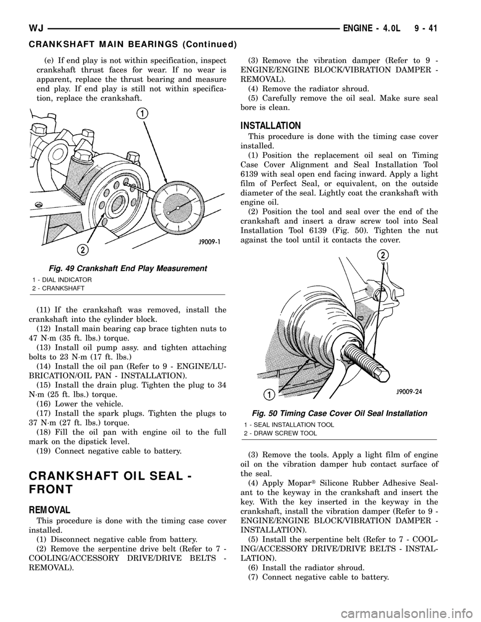
(2) Position the tool and seal over the end of the
crankshaft and insert a draw screw tool into Seal
Installation Tool 6139 (Fig. 50). Tighten the nut
against the tool until it contacts the cover.
(3) Remove the tools. Apply a light film of engine
oil on the vibration damper hub contact surface of
the seal.
(4) Apply MopartSilicone Rubber Adhesive Seal-
ant to the keyway in the crankshaft and insert the
key. With the key inserted in the keyway in the
crankshaft, install the vibration damper (Refer to 9 -
ENGINE/ENGINE BLOCK/VIBRATION DAMPER -
INSTALLATION).
(5) Install the serpentine belt (Refer to 7 - COOL-
ING/ACCESSORY DRIVE/DRIVE BELTS - INSTAL-
LATION).
(6) Install the radiator shroud.
(7) Connect negative cable to battery.
Fig. 49 Crankshaft End Play Measurement
1 - DIAL INDICATOR
2 - CRANKSHAFT
Fig. 50 Timing Case Cover Oil Seal Installation
1 - SEAL INSTALLATION TOOL
2 - DRAW SCREW TOOL
WJENGINE - 4.0L 9 - 41
CRANKSHAFT MAIN BEARINGS (Continued)
Page 1292 of 2199
VIBRATION DAMPER
REMOVAL
(1) Disconnect negative cable from battery.
(2) Remove the serpentine drive belt (Refer to 7 -
COOLING/ACCESSORY DRIVE/DRIVE BELTS -
REMOVAL) and fan shroud.
(3) Remove the vibration damper retaining bolt
and washer.
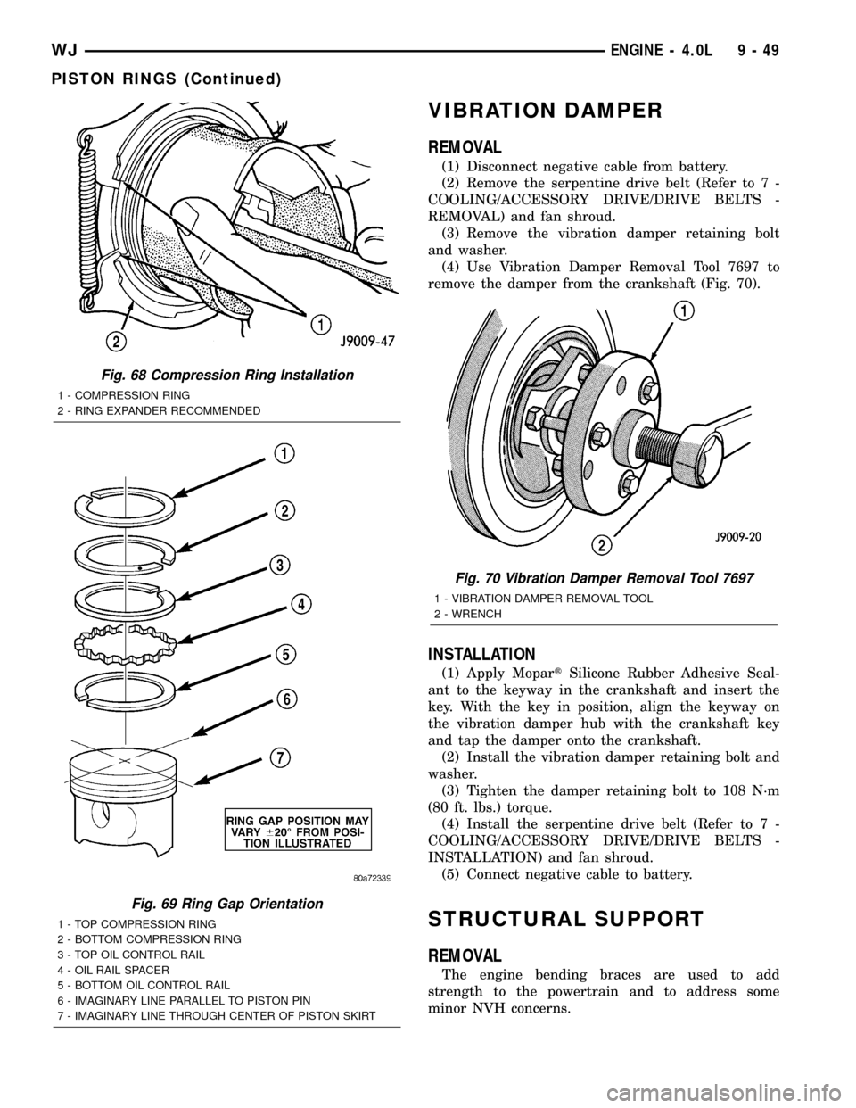
(4) Use Vibration Damper Removal Tool 7697 to
remove the damper from the crankshaft (Fig. 70).
INSTALLATION
(1) Apply MopartSilicone Rubber Adhesive Seal-
ant to the keyway in the crankshaft and insert the
key. With the key in position, align the keyway on
the vibration damper hub with the crankshaft key
and tap the damper onto the crankshaft.
(2) Install the vibration damper retaining bolt and
washer.
(3) Tighten the damper retaining bolt to 108 N´m
(80 ft. lbs.) torque.
(4) Install the serpentine drive belt (Refer to 7 -
COOLING/ACCESSORY DRIVE/DRIVE BELTS -
INSTALLATION) and fan shroud.
(5) Connect negative cable to battery.
STRUCTURAL SUPPORT
REMOVAL
The engine bending braces are used to add
strength to the powertrain and to address some
minor NVH concerns.
Fig. 68 Compression Ring Installation
1 - COMPRESSION RING
2 - RING EXPANDER RECOMMENDED
Fig. 69 Ring Gap Orientation
1 - TOP COMPRESSION RING
2 - BOTTOM COMPRESSION RING
3 - TOP OIL CONTROL RAIL
4 - OIL RAIL SPACER
5 - BOTTOM OIL CONTROL RAIL
6 - IMAGINARY LINE PARALLEL TO PISTON PIN
7 - IMAGINARY LINE THROUGH CENTER OF PISTON SKIRT
Fig. 70 Vibration Damper Removal Tool 7697
1 - VIBRATION DAMPER REMOVAL TOOL
2 - WRENCH
WJENGINE - 4.0L 9 - 49
PISTON RINGS (Continued)
Page 1302 of 2199
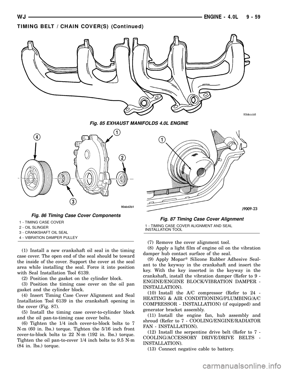
(1) Install a new crankshaft oil seal in the timing
case cover. The open end of the seal should be toward
the inside of the cover. Support the cover at the seal
area while installing the seal. Force it into position
with Seal Installation Tool 6139.
(2) Position the gasket on the cylinder block.
(3) Position the timing case cover on the oil pan
gasket and the cylinder block.
(4) Insert Timing Case Cover Alignment and Seal
Installation Tool 6139 in the crankshaft opening in
the cover (Fig. 87).
(5) Install the timing case cover-to-cylinder block
and the oil pan-to-timing case cover bolts.
(6) Tighten the 1/4 inch cover-to-block bolts to 7
N´m (60 in. lbs.) torque. Tighten the 5/16 inch front
cover-to-block bolts to 22 N´m (192 in. lbs.) torque.
Tighten the oil pan-to-cover 1/4 inch bolts to 9.5 N´m
(84 in. lbs.) torque.(7) Remove the cover alignment tool.
(8) Apply a light film of engine oil on the vibration
damper hub contact surface of the seal.
(9) Apply MopartSilicone Rubber Adhesive Seal-
ant to the keyway in the crankshaft and insert the
key. With the key inserted in the keyway in the
crankshaft, install the vibration damper (Refer to 9 -
ENGINE/ENGINE BLOCK/VIBRATION DAMPER -
INSTALLATION).
(10) Install the A/C compressor (Refer to 24 -
HEATING & AIR CONDITIONING/PLUMBING/A/C
COMPRESSOR - INSTALLATION) (if equipped) and
generator bracket assembly.
(11) Install the engine fan, hub assembly and
shroud (Refer to 7 - COOLING/ENGINE/RADIATOR
FAN - INSTALLATION).
(12) Install the serpentine drive belt (Refer to 7 -
COOLING/ACCESSORY DRIVE/DRIVE BELTS -
INSTALLATION).
(13) Connect negative cable to battery.
Fig. 85 EXHAUST MANIFOLDS 4.0L ENGINE
Fig. 86 Timing Case Cover Components
1 - TIMING CASE COVER
2 - OIL SLINGER
3 - CRANKSHAFT OIL SEAL
4 - VIBRATION DAMPER PULLEYFig. 87 Timing Case Cover Alignment
1 - TIMING CASE COVER ALIGNMENT AND SEAL
INSTALLATION TOOL
WJENGINE - 4.0L 9 - 59
TIMING BELT / CHAIN COVER(S) (Continued)
Page 1303 of 2199
TIMING BELT/CHAIN AND
SPROCKETS
REMOVAL
(1) Disconnect negative cable from battery.
(2) Remove the fan and shroud (Refer to 7 -
COOLING/ENGINE/RADIATOR FAN - REMOVAL).
(3) Remove the serpentine drive belt (Refer to 7 -
COOLING/ACCESSORY DRIVE/DRIVE BELTS -
REMOVAL).
(4) Remove the crankshaft vibration damper (Refer
to 9 - ENGINE/ENGINE BLOCK/VIBRATION
DAMPER - REMOVAL).
(5) Remove the timing case cover (Refer to 9 -
ENGINE/VALVE TIMING/TIMING BELT / CHAIN
COVER(S) - REMOVAL).
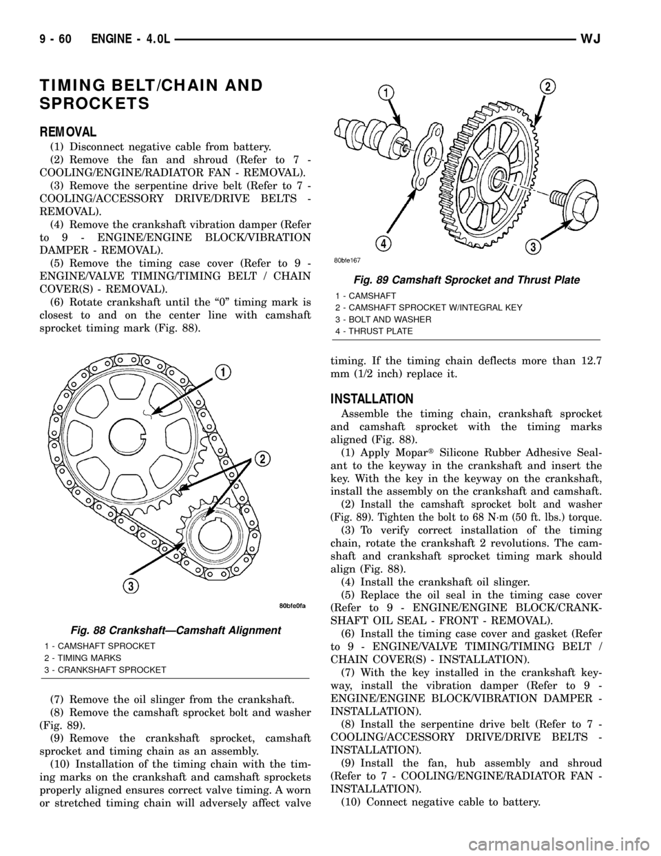
(6) Rotate crankshaft until the ª0º timing mark is
closest to and on the center line with camshaft
sprocket timing mark (Fig. 88).
(7) Remove the oil slinger from the crankshaft.
(8) Remove the camshaft sprocket bolt and washer
(Fig. 89).
(9) Remove the crankshaft sprocket, camshaft
sprocket and timing chain as an assembly.
(10) Installation of the timing chain with the tim-
ing marks on the crankshaft and camshaft sprockets
properly aligned ensures correct valve timing. A worn
or stretched timing chain will adversely affect valvetiming. If the timing chain deflects more than 12.7
mm (1/2 inch) replace it.
INSTALLATION
Assemble the timing chain, crankshaft sprocket
and camshaft sprocket with the timing marks
aligned (Fig. 88).
(1) Apply MopartSilicone Rubber Adhesive Seal-
ant to the keyway in the crankshaft and insert the
key. With the key in the keyway on the crankshaft,
install the assembly on the crankshaft and camshaft.
(2)
Install the camshaft sprocket bolt and washer
(Fig. 89). Tighten the bolt to 68 N´m (50 ft. lbs.) torque.
(3) To verify correct installation of the timing
chain, rotate the crankshaft 2 revolutions. The cam-
shaft and crankshaft sprocket timing mark should
align (Fig. 88).
(4) Install the crankshaft oil slinger.
(5) Replace the oil seal in the timing case cover
(Refer to 9 - ENGINE/ENGINE BLOCK/CRANK-
SHAFT OIL SEAL - FRONT - REMOVAL).
(6) Install the timing case cover and gasket (Refer
to 9 - ENGINE/VALVE TIMING/TIMING BELT /
CHAIN COVER(S) - INSTALLATION).
(7) With the key installed in the crankshaft key-
way, install the vibration damper (Refer to 9 -
ENGINE/ENGINE BLOCK/VIBRATION DAMPER -
INSTALLATION).
(8) Install the serpentine drive belt (Refer to 7 -
COOLING/ACCESSORY DRIVE/DRIVE BELTS -
INSTALLATION).
(9) Install the fan, hub assembly and shroud
(Refer to 7 - COOLING/ENGINE/RADIATOR FAN -
INSTALLATION).
(10) Connect negative cable to battery.
Fig. 88 CrankshaftÐCamshaft Alignment
1 - CAMSHAFT SPROCKET
2 - TIMING MARKS
3 - CRANKSHAFT SPROCKET
Fig. 89 Camshaft Sprocket and Thrust Plate
1 - CAMSHAFT
2 - CAMSHAFT SPROCKET W/INTEGRAL KEY
3 - BOLT AND WASHER
4 - THRUST PLATE
9 - 60 ENGINE - 4.0LWJ